Handbook Of Shaft Alignment Episode 3 Part 1 pdf
Bạn đang xem bản rút gọn của tài liệu. Xem và tải ngay bản đầy đủ của tài liệu tại đây (697.66 KB, 30 trang )
Gear
Pump
10 in.
Up
Side view
Scale :
30 mils
T
B
EW
0
T
B
EW
0
PumpGear output
+20
−66 −2
−68
−32
+52
Gear
Pump
Scale:
East
Top View
10 in.
50 mils
T
B
EW
T
B
EW
PumpGear output
0
+64
0
+84
View looking east
24 in.48 in. 14 in.10 in.
1 in.
Motor Gear
32 in.
Pump
0
50
10
40
20
30
+
_
10
40
20
30
0
50
10
40
20
30
+
_
10
40
20
30
0
50
10
40
20
30
+
_
10
40
20
30
0
50
10
40
20
30
+
_
10
40
20
30
2 in.
28 in. 32 in.
0
50
10
40
+
_
10
40
20
30
0
50
10
40
20
30
+
_
10
40
20
30
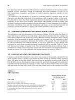
FIGURE 17.9 Side and top view alignment models of just the gear and the pump.
Piotrowski / Shaft Alignment Handbook, Third Edition DK4322_C017 Final Proof page 570 26.9.2006 8:41pm
570 Shaft Alignment Handbook, Third Edition
Motor
Gear
10 in.
Up
Side view
Scale:
Motor
Gear
Scale:
East
Top view
30 mils
10 in.
50 mils
T
B
0
T
B
EEWW
0
Motor Gear input
−
50
−
40+70
+30
+20−70
T
B
T
B
EEWW
Motor Gear input
−1100+900
63 mils down
31 mils down
37 mils east
10 mils east
FIGURE 17.10 Required moves to align the motor to the gear.
Piotrowski / Shaft Alignment Handbook, Third Edition DK4322_C017 Final Proof page 571 26.9.2006 8:41pm
Aligning Multiple-Element Drive Systems 571
Gear
Pump
10 in.
Up
Side view
Scale:
30 mils
T
B
E
0
T
B
EW W
0
PumpGear output
+20
−66 −2
−68
−32
+52
Gear
Pump
Scale:
East
Top view
10 in.
50 mils
T
B
T
B
EEWW
PumpGear output
0
+64
0
+84
63 mils down
93 mils down
120 mils east
220 mils east
FIGURE 17.11 Required moves to align the pump to the gear.
Piotrowski / Shaft Alignment Handbook, Third Edition DK4322_C017 Final Proof page 572 26.9.2006 8:41pm
572 Shaft Alignment Handbook, Third Edition
Motor
Gear
20 in.
Up
Side view
Scale:
Scale:
East
Top view
50 mils
10 in.
100 mils
63 mils down 31 mils down
37 mils east10 mils east
Pump
Motor
Gear Pump
FIGURE 17.12 Three-element alignment model showing the gear and motor shafts only.
Piotrowski / Shaft Alignment Handbook, Third Edition DK4322_C017 Final Proof page 573 26.9.2006 8:41pm
Aligning Multiple-Element Drive Systems 573
Motor
Gear
20 in.
Up
Side view
Scale:
Scale:
East
Top view
50 mils
10 in.
100 mils
63 mils down 93 mils down
Pump
Motor
Gear Pump
120 mils east 220 mils east
FIGURE 17.13 Three-element alignment model showing all three shafts.
Piotrowski / Shaft Alignment Handbook, Third Edition DK4322_C017 Final Proof page 574 26.9.2006 8:41pm
574 Shaft Alignment Handbook, Third Edition
Figure 17.14 shows the misalignment between the motor and gear shafts in the side and top
views using the line to points reverse indicator modeling technique. Figure 17.15 shows the
misalignment between the gear and pump shafts in the side and top views. It does not matter
which set of readings is plotted first, the motor to gear or the gear to pump. Notice that the
Motor
Gear
20 in.
Up
Side view
Scale:
Scale:
East
Top View
50 mils
10 in.
100 mils
Pump
Motor
Gear Pump
T
B
EW
0
T
B
EW
0
Motor Gear input
−50
−40+70
+30
+20−70
T
B
EW
T
B
EW
Motor Gear input
−1100+900
FIGURE 17.14 Three-element alignment model plotting the motor and gear shafts using the line to
points reverse indicator modeling technique.
Piotrowski / Shaft Alignment Handbook, Third Edition DK4322_C017 Final Proof page 575 26.9.2006 8:41pm
Aligning Multiple-Element Drive Systems 575
Motor
Gear
20 in.
Up
Side view
Scale:
Scale:
East
Top view
50 mils
10 in.
100 mils
Pump
Motor
Gear Pump
T
B
EW
0
T
B
EW
0
PumpGear output
+20
−66 −2
−68
−32
+52
T
B
EW
T
B
EW
PumpGear output
0
+64
0
+84
FIGURE 17.15 Three-element alignment model plotting the gear and pump shafts using the line to
points reverse indicator modeling technique.
Piotrowski / Shaft Alignment Handbook, Third Edition DK4322_C017 Final Proof page 576 26.9.2006 8:41pm
576 Shaft Alignment Handbook, Third Edition
positions of the shafts in Figure 17.13 are identical to the positions of the shafts in Figure
17.15 even though two different methods were used to generate the two graphs.
Again, just as in modeling two-shaft drive systems, all that has been accomplished with the
graph is that the positions of the shafts have been determined. At this point, it is imperative
that the restrictions in the up or down and east or west directions be determined at every
bolting plane on all three machines and transferred onto the graph. Once this has been done,
the final desired overlay line can be drawn onto the graph and the movement solutions at all
of the bolting or translation planes can be determined and executed. An example of this is
illustrated in Figure 17.16 showing the amount of existing shims and the lateral movement
restrictions at each bolting plane. Notice that in the side view if you were to name any one of
the machines as a ‘‘stationary’’ machine, the vertical restriction would have prevented you
from aligning the drive system; and in the top view if you were to name either the gear or the
pump as a stationary machine, the lateral restriction would have prevented you from aligning
the drive system.
17.5 MIXING DIFFERENT ALIGNMENT MEASUREMENT METHODS
In some situations, more than one alignment measurement method could be (or may have to
be) employed to measure each set of shafts. Figure 17.17 through Figure 17.19 show how you
can use different alignment measurement methods and still model the machinery positions.
Two electric motors are coupled together to drive a gearbox and a compressor. A laser–
detector shaft alignment system was used to measure the alignment between the two motors
(Motor A and Motor B). Reverse Indicator readings were taken between Motor B and the
gearbox. The shaft to coupling spool method was employed between the gear output shaft
and the compressor. Figure 17.17 shows the dimensions of the four-element drive system, the
information gathered from the laser–detector shaft alignment system, the reverse indicator
measurements (before and after sag compensation), the shaft to coupling spool measurements
(before and after sag compensation), the amount of existing shims under each bolting plane,
and the lateral movement restrictions at each bolting plane. You need every piece of infor-
mation shown in Figure 17.17 to determine how to correct the misalignment condition that
exists on this drive system.
Figure 17.18 shows the side view alignment model of all four shafts and the vertical
restriction boundary. The gear shafts were placed on the graph paper centerline and each
shaft was referenced from the gear outward. Figure 17.19 shows the top view alignment model
of all four shafts and the lateral restriction envelope. Again, the gear was placed on the graph
paper centerline and each shaft was referenced from that point outward. Carefully study both
alignment models to determine how the shafts were constructed.
Despite the fact that three different alignment measurement methods and tools were used
to determine the relative positions of each set of shafts, the entire drive train can still be
modeled on graph paper. As you can see from the shaft positions in the side view, attempting
to call Motor A, Motor B, or the gear as the ‘‘fixed’’ or stationary machine will result in a lot
of headaches and unnecessary work. In the top view, attempting to call any of the four
machines as the fixed or stationary machine will result in unforeseen situations and unneces-
sary work. It should become obvious why it is recommended that the multiple-element drive
train alignment laws mentioned above should be adhered to when aligning drive systems of
this complexity.
Piotrowski / Shaft Alignment Handbook, Third Edition DK4322_C017 Final Proof page 577 26.9.2006 8:41pm
Aligning Multiple-Element Drive Systems 577
17.6 MODELING RIGHT-ANGLE DRIVE SYSTEMS
So far, we have examined rotating machinery drive systems that are horizontally mounted,
direct in-line machinery. But not all drive systems are configured that way. Some drive trains
are arranged in an ‘‘L’’ shape, commonly referred to as right-angle drives. A right-angled
Motor
Gear
20 in.
Up
Side view
Scale:
Scale:
East
Top view
50 mils
10 in.
100 mils
Pump
Motor
Gear Pump
Lateral movement restriction points
Baseplate restriction points
Overlay line
38 mils up
47 mils up
45 mils down
Pivot here
Pivot here
25 mils down
Overlay line
No lateral moves required on motor
57 mils west
80 mils west
83 mils east
Pivot here
FIGURE 17.16 Possible alignment corrective moves after overlaying the boundary conditions.
Piotrowski / Shaft Alignment Handbook, Third Edition DK4322_C017 Final Proof page 578 26.9.2006 8:41pm
578 Shaft Alignment Handbook, Third Edition
Gear
Motor A
Compressor
62 in.
62 in.
50 in.
20 in.
10 in.
8 in. 10 in.
12 in.
8 in.
Motor B
16 in.
4 in.
Flex point
Flex point
0
50
10
40
20
30
+
_
10
40
20
30
0
50
10
40
20
30
+
_
10
40
20
30
12 in.
14 in.12 in.
380" overall length from
outboard bolts of Motor A to
outboard bolts of compressor.
Motor B
Bracket sag = 6 mils
Sa
g
compensated
readings
Field readings
Gear to spool Compressor to spool
0
−30
–20
Bracket sag = 10 mils
Sag
compensated
readings
Field readings
+60
A laser alignment system was
used between Motor A and
Motor B. With Motor A named
as the stationary machine, the
following moves on Motor B
were indicated by the laser:
lower “near” foot 40 mils
raise “far” foot 15 mils
move “near” foot 50 mils east
move “far” foot 45 mils west
−43
−23
T
B
E
W
0
25 mils shims
60 east • 20 west
80 mils shims
80 east • 0 west
50 mils shims
40 east • 40 west
40 mils shims
16 east • 60 west
30 mils shims
30 east • 50 west
No shims
60 east • 0 west
Gear
+14
+30
T
B
EW
0
T
B
EW
0
T
B
EW
0
T
B
EW
0
T
B
EW
0
T
B
EW
0
T
B
EW
0
View looking east
−66
+44
−40
−20
+17
+33
−60
+50
−30
+40
+5
–25
–15
+65
–20
+50
0
50
10
40
20
30
+
_
10
40
20
30
0
50
10
40
20
30
+
_
10
40
20
30
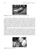
FIGURE 17.17
Four-element drive system arrangement with all the required
alignment information.
Piotrowski / Shaft Alignment Handbook, Third Edition DK4322_C017 Final Proof page 579 26.9.2006 8:41pm
Aligning Multiple-Element Drive Systems 579
Scale:
20 in.
50 mils
Up
Side view
Gear
Motor A
Compressor
Motor B
A laser alignment system was
used between Motor A and
Motor B. With Motor A named
as the stationary machine, the
following moves on Motor B
were indicated by the laser:
lower “near” foot 40 mils
raise “far” foot 15 mils
T
B
0
T
B
0
T
B
E
E
WW E
E
W
W
0
T
B
0
Sag
compensated
readings
−40
+36
Sag
compensated
readings
−50
−106
Motor B
Gear to spool
Compressor to spool
Gear
Baseplate restriction points
0
50
10
40
20
30
+
_
10
40
20
30
0
50
10
40
20
30
+
_
10
40
20
30
FIGURE 17.18
(See color insert following page 322.) Four-element drive system
side view alignment model of all four shafts and the vertical restriction
boundary.
Piotrowski / Shaft Alignment Handbook, Third Edition DK4322_C017 Final Proof page 580 26.9.2006 8:41pm
580 Shaft Alignment Handbook, Third Edition
Scale:
20 in.
50 mils
Gear
Motor A
Compressor
Motor B
Lateral movement restriction points
East
Top view
Motor B
Field readings
Gear to spool Compressor to spool
0
−30
−20
Field readings
+60
−43
−23
T
B
EW
EW
E
E W
W
0
Gear
+14
+30
T
B
0
T
B
0
T
B
0
−66
+44
−30
+40
+30
0
−80
0
0
+20
T
B
EE
W
EW EW
W
0
+16
T
B
T
B
T
B
A laser alignment system was
used between Motor A and
Motor B. With Motor A named
as the stationary machine, the
following moves on Motor B
were indicated by the laser:
move “near” foot 50 mils east
move “far” foot 45 mils west
0
50
10
40
20
30
+
_
10
40
20
30
0
50
10
40
20
30
+
_
10
40
20
30
FIGURE 17.19
(See color insert following page 322.) Four-element drive system
side view alignment model of all four shafts and the lateral restriction
envelope.
Piotrowski / Shaft Alignment Handbook, Third Edition DK4322_C017 Final Proof page 581 26.9.2006 8:41pm
Aligning Multiple-Element Drive Systems 581
gearbox is flexibly coupled to a driver on the input side and to some driven machine on its
output side. The goal is to align the centerline of rotation of the driver and the input shaft of
the gear and the driven unit to the output shaft of the gear.
There are two tricks to this modeling method. One is to plot the graph in the ‘‘dual scale’’
mode similar to the method used for face–rim plotting covered in Chapter 11. The other trick
is to ‘‘fold’’ one of the views of the alignment model where the right angle occurs in the drive
system.
The sample problem shown in Figure 17.20 comprises an electric motor coupled to a speed
reducing right-angled gear that drives a roll. The reverse indicator was employed between the
Roll
48 in.
8 in.
4 in.
Motor
Gear
0
50
10
40
20
30
+
_
10
40
20
30
0
50
10
40
20
30
+
_
10
40
20
30
82 in.
Face reading diameter = 12 in.
Rim bracket sag = 6 mils
Face bracket sag = 2 mils
Field readings
T
B
N +9
0
Gear to roll
+24
−32
−56
0
+8
−1 S
Gear
Bracket sag = 6 mils
T
B
WW
EE
0
Motor
T
B
0
+1
−28
−29
+13
+46
+33
Field readings
East
North
0
50
10
40
20
30
+
_
10
40
20
30
0
50
10
40
20
30
+
_
10
40
20
30
56 in.
18 in.
12 in. 8 in.
2 in.
16 in.
8 in.
10 in.
20 in.
2 in.
FIGURE 17.20 Right-angle drive system.
Piotrowski / Shaft Alignment Handbook, Third Edition DK4322_C017 Final Proof page 582 26.9.2006 8:41pm
582 Shaft Alignment Handbook, Third Edition
motor and the input shaft of the gear. The face–rim method was used to capture the alignment
data between the motor and the output shaft of the gear.
Figure 17.21 shows the top view of the motor–gear–roll drive system. The alignment
plotting techniques in this view are straightforward and follow the modeling principles
explained in Chapter 10 and Chapter 11.
Figure 17.22 shows the side view of the drive system. There is a slight ‘‘trick’’ in this
alignment model view however. The side view alignment model is split or ‘‘folded’’ as if you
were viewing it from two different directions. Figure 17.23 shows how the alignment model is
folded through the center of the right-angled gear (i.e., it is as if you folded the graph paper
Top view
Scale:
5 in.
or 50 mils
5 in.
or 50 mils
Face reading diameter = 12 in.
N 0
−10 S
Gear to roll
0
−80
Gear
T
B
WE
Motor
T
B
−30 0
−20
0
Roll
Motor
Gear
East
North
South
West
WE
FIGURE 17.21 Right-angle drive system top view alignment model.
Piotrowski / Shaft Alignment Handbook, Third Edition DK4322_C017 Final Proof page 583 26.9.2006 8:41pm
Aligning Multiple-Element Drive Systems 583
through the center of the right-angle gear through its vertical axis). The left side of the side
view alignment model shows what the position of the motor shaft and input shaft of the gear
would look like if you were looking to the east. The right side of the side view alignment
model shows what the position of the output shaft of the gear and the roll would look like if
you were looking to the south. Figure 17.24 illustrates how each bolting plane on the right-
angled gearbox is identified depending on which direction you are viewing in the side view
alignment model. Figure 17.25 shows a possible alignment corrective move in the vertical
direction assuming there were no shims under any of the machinery feet.
Up
Side view
Scale:
10 in.
or 20 mils
10 in.
or 20 mils
Gear
Bracket sag = 6 mils
Sag compensated readings
T
B
WE
0
Motor
T
B
W
E
0
+1
−28
−29
+13
+46
+33
Field readings
T
B
WE
0
T
B
WE
0
+4
−22
−26
+16
+52
+36
RollMotor Gear
Face reading diameter = 12Љ
Rim bracket sag = 6 mils
Face bracket sag = 2 mils
Field readings
T
B
N +9
0
Gear to roll
+24
−32
−56
0
+8
−1S
T
B
N +10
0
Gear to roll
+27
−26
−53
0
+10
0 S
Sag compensated readings
Right-angle bend plane
View looking east View looking south
FIGURE 17.22 Right-angle drive system side view alignment model.
Piotrowski / Shaft Alignment Handbook, Third Edition DK4322_C017 Final Proof page 584 26.9.2006 8:41pm
584 Shaft Alignment Handbook, Third Edition
Roll
Motor
Gear
Up
v
iew
Roll
G
ear
Sca
le
:
10
i
n.
o
r 20
m
ils
10
i
n
c
h
e
s
o
r
20
m
i
l
s
Mo
t
o
r
S
ide
Alignment model “fold axis”
South
East
Up
Side view
Scale:
10 inches
or 20 mils
RollMotor
Right-angle gear
“fold” axis
10 in.
or 20 mils
Gear
FIGURE 17.23 (See color insert following page 322.) Right-angle drive system ‘‘folded’’ side view
alignment model.
Up
Side view
RollMotor
East
South
Gear
FIGURE 17.24 Bolt plane identification on the right-angled gear.
Piotrowski / Shaft Alignment Handbook, Third Edition DK4322_C017 Final Proof page 585 26.9.2006 8:41pm
Aligning Multiple-Element Drive Systems 585
To determine the corrective moves for this drive system in the top view, a clear transpar-
ency with the right-angled gear shafts transferred to the transparency will be of assistance in
determining what lateral moves need to be made to correct the misalignment condition as
shown in Figure 17.26. In addition, we need to determine the lateral movement restrictions
(i.e., the bolt bound conditions) on all three machines in the drive system. The gaps between
the foot bolts and the holes in the motor and the pillow block bearings in the roll are fairly
straightforward. Because the motor will only need to be positioned in the east to west
direction and the roll in the north to south direction, the gaps between the foot bolt and holes
on the east and west sides and the gaps between the pillow block bearing and bolt holes on
the north and south sides, respectively, need to be detrmined. The gaps in the holes of the
ight-angled gear however need to be determined in all four directions as the gear may have
to be rotated through its vertical axis. Figure 17.27 shows what gaps are needed to be
measured on the gear feet. These restrictions are then transferred to the top view align-
ment model. The restrictions on the motor and roll can be illustrated as single-plane
restriction points, the restrictions on the gear need to be illustrated as ‘‘restriction rings’’
as shown in Figure 17.28. The clear transparency showing the right-angled gear shafts and
the four corner bolts is pitched to insure that the projected centerlines of the input and
output shafts of the gear fall within the lateral movement boundaries of both the motor
andtherollandalsowithintherestriction rings on the gear itself as shown in Figure
17.29. Once the transparency is positioned to stay within the lateral movement boundaries
of all three machines, the required moves can then be determined to correct the misalign-
ment condition.
Up
Side view
Scale:
10 in.
or 20 mils
10 in.
or 20 mils
RollMotor Gear
8 mils up
Pivot here
Pivot here
35 mils up
53 mils up
2 mils up
3 mils up
FIGURE 17.25 Possible vertical alignment corrective moves with no shims under any machinery feet.
Piotrowski / Shaft Alignment Handbook, Third Edition DK4322_C017 Final Proof page 586 26.9.2006 8:41pm
586 Shaft Alignment Handbook, Third Edition
right angle gear
FIGURE 17.26 Right-angle gear overlay transparency for assistance in the top view alignment model.
East
North
South
West
East gap
West gap
North gap
South gap
East gap
West gap
North gap
South gap
East gap
West gap
North gap
South gap
East gap
West gap
North gap
South gap
FIGURE 17.27 Lateral movement restrictions on the gear in all four directions are needed.
Piotrowski / Shaft Alignment Handbook, Third Edition DK4322_C017 Final Proof page 587 26.9.2006 8:41pm
Aligning Multiple-Element Drive Systems 587
17.7 FINAL COMMENTS ON ALIGNING MULTIPLE-ELEMENT
DRIVE TRAINS
Multiple-element drive trains can get extremely complex if you do not keep your wits about
you when aligning the machinery. Some drive systems can consist of up to 20 or more
elements in ‘‘L’’ shapes, ‘‘U’’ shapes, ‘‘S’’ shapes, or other ridiculously complex arrangements.
Regardless of how many pieces of machinery are in the drive train or how the shaft-to-shaft
measurements were taken, the positions of all the machinery can be accurately illustrated on
Top view
Scale:
5 in.
or 50 mils
5 in.
or 50 mils
Roll
Motor
Gear
East
North
South
West
Lateral movement restriction
points on motor and roll
Lateral movement restriction
points on right-angle gear
FIGURE 17.28 Top view alignment model showing the boundary conditions.
Piotrowski / Shaft Alignment Handbook, Third Edition DK4322_C017 Final Proof page 588 26.9.2006 8:41pm
588 Shaft Alignment Handbook, Third Edition
Top view
Scale:
5 in.
or 50 mils
5 in.
or 50 mils
Roll
Motor
Gear
East
North
South
West
Lateral movement restriction points
37 mils west
10 mils west
12 mils east
15 mils north
13 mils south
13 mils north
FIGURE 17.29 (See color insert following page 322.) Top view alignment model showing possible
alignment corrective moves in the lateral direction staying within the boundary conditions.
Piotrowski / Shaft Alignment Handbook, Third Edition DK4322_C017 Final Proof page 589 26.9.2006 8:41pm
Aligning Multiple-Element Drive Systems 589
an alignment model as shown in this chapter. Once the movement restrictions are superim-
posed onto the alignment model to visualize your boundary conditions, usually by moving
more than one element, an effective alignment solution can be attained.
REFERENCE
Piotrowski, J., Aligning multiple-element drive trains and right-angle drives,’’ P=PM Technology, 5(2),
1992.
Piotrowski / Shaft Alignment Handbook, Third Edition DK4322_C017 Final Proof page 590 26.9.2006 8:41pm
590 Shaft Alignment Handbook, Third Edition
18
Aligning V-Belt Drives
Up to this point, the machinery discussed in this book has been directly driven by flexible or
rigid couplings, but there are alternative power transmission schemes that are frequently used
in industry known as belt drives. Examples of belt drive machinery can be seen in Figure 18.1
through Figure 18.4.
18.1 BELT DRIVE SYSTEMS—ADVANTAGES AND DISADVANTAGES
There are several advantages and disadvantages of belt drive equipment:
Advantages
.
Inexpensive way to reduce or increase speed.
.
Provides some cushioning against shock loads during start up and operation.
.
Does not require lubrication like a gearbox.
.
Because of the flexibility in belts, alignment is not as critical as direct drive systems.
.
In certain instances, placing two shafts parallel to each other rather than in line can save
space.
.
When the drive system is off-line, visual inspections of the belts are fairly easy to do.
.
If the speed of the driven machine is too fast or too slow for the operational requirements,
changing the diameter of the sheaves to adjust the speed is fairly inexpensive.
Disadvantages
.
Incapable of delivering a precise nonvarying speed of the driven machine as belts will
wear and eventually begin to slip over time.
.
Correct belt tension is difficult to achieve and may change dramatically with new belts in
a short period of time.
.
Belt tension places radial loads on bearings and shafts even if the alignment is correct.
.
Sheaves are frequently found to be eccentric or skew bored causing excessive vibration
and reduced belt life.
.
Some sheave designs have a taper lock bushing that will, if the installer is not careful,
draw the sheave onto the bushing incorrectly inducing an excessive radial or face runout
condition.
18.2 V-BELT STANDARDS INFORMATION
Standard cross-sectional and length dimensions have been established for V-belts as shown
in Figure 18.5 and Figure 18.6. Figure 18.7 shows how to calculate the required length of
a V-belt.
Piotrowski / Shaft Alignment Handbook, Third Edition DK4322_C018 Final Proof page 591 28.9.2006 7:15pm
591
FIGURE 18.1 Belt driven fan.
FIGURE 18.2 Belt driven fan.
Piotrowski / Shaft Alignment Handbook, Third Edition DK4322_C018 Final Proof page 592 28.9.2006 7:15pm
592 Shaft Alignment Handbook, Third Edition
18.3 SHEAVE INFORMATION
Standard information on sheaves is shown in Figure 18.8.
18.4 V-BELT RECOMMENDATIONS AND RULES OF THUMB
Here are some guidelines for successful, long-term belt operation:
.
4000 ft=min is a good speed for V-belts to run at. Trouble can begin to occur below 1000
ft=min and above 5000 ft=min.
.
Typically, the center-to-center distance between shafts should neither exceed three times
the sum of the sheave diameters nor should it be less than the largest sheave diameter.
.
Belts should be tensioned to 1=64 in. deflection per inch distance between shaft centers
(refer to belt tensioning guidelines and procedures).
.
Typically, sheave misalignment should be less than 1.58 (i.e., 1=8 in. per foot or approxi-
mately 10 mils=in.).
.
Do not mix new and old belts or belts from different manufacturers.
.
Keep debris from jamming between belts and sheaves during operation or replacement.
.
Salads get dressing, not belts.
FIGURE 18.3 Belt driven fan.
Piotrowski / Shaft Alignment Handbook, Third Edition DK4322_C018 Final Proof page 593 28.9.2006 7:15pm
Aligning V-Belt Drives 593
.
Worn sheaves may shorten belt life by 50%.
.
For a specific shaft speed, shorter belts will not last as long as longer belts.
18.5 SHEAVE AND BELT WEAR
Sheave and belt wear indicator should be used to determine if these components are worn
excessively. These Go=No go gauges are typically made out of plastic and can be obtained
from your power transmission supplier. Figure 18.9 shows what to look for when using the
gauges.
FIGURE 18.4 Belt driven dredge.
Piotrowski / Shaft Alignment Handbook, Third Edition DK4322_C018 Final Proof page 594 28.9.2006 7:15pm
594 Shaft Alignment Handbook, Third Edition