Handbook Of Shaft Alignment Episode 3 Part 8 pps
Bạn đang xem bản rút gọn của tài liệu. Xem và tải ngay bản đầy đủ của tài liệu tại đây (995.37 KB, 30 trang )
Piotrowski / Shaft Alignment Handbook, Third Edition DK4322_A001 Final Proof page 780 29.9.2006 7:46pm
Appendix J
Alignment Internet Web Sites
Company or Organization Web Site
Accushim Inc. http:==www.accushim.com=v180.html
Alignment Services Inc. http:==www.alignmentservicesinc.com=
Alignment Supplies Inc. http:==www.alignmentsupplies.com=
Automated Precision http:==www.apisensor.com=
Brunson Instrument Co. http:==www.brunson.us=
Aline Mfg. Inc. http:==alinemfg.com=
Damalini http:==www.damalini.com=
Donaldson Garrett & Associates Inc. http:==www.dg-a.com=
Dreyco Mechanical Services Inc. http:==www.dreyco-mechanical.com=index.asp
Fixturlaser http:==www.fixturlaser.com=
James L. Griffin Co. Inc. http:==www.jlgriffin.com=
Hamar Laser http:==www.hamarlaser.com=
Indikon Co. Inc. http:==www.indikon.com=
Kara Co. http:==www.karaco.com=
Laser Tools Co. Inc. http:==www.lasertoolsco.com=
Ludeca http:==www.ludeca.com=
Newman Tools Inc. http:==www.newmantools.com=shaft.htm
New Standard Institute http:==www.newstandardinstitute.com=index.cfm
Oasis Alignment Services http:==www.oasisalignment.com=
Oxford Engineering Co. http:
==www.oxfordengineeringco.com=
Peterson Alignment Tools co. http:==www.petersontools.com=
Pinpoint Laser Systems http:==www.pinlaser.com=
Pruftechnik http:==www.pruftechnik.com=index__.htm
R&T Factors Inc. http:==rtfactors.com=
Schaeffer Precision Alignment Inc. http:==www.schaefferprecision.com=
SPM Instrument http:==www.spminstrument.com=
Turbine Tools http:==www.turbinetools.com=
Turvac Inc. http:==www.turvac.com=
Unisorb http:==www.unisorb.com=
Universal Technologies Inc. http:==www.unitechinc.com=
Update International http:==www.update-intl.com=
Vibralign http:==www.vibralign.com=
Piotrowski / Shaft Alignment Handbook, Third Edition DK4322_A001 Final Proof page 781 29.9.2006 7:46pm
781
Piotrowski / Shaft Alignment Handbook, Third Edition DK4322_A001 Final Proof page 782 29.9.2006 7:46pm
Appendix K
Single Plane Balancing
Single plane balancing procedure
Induction motor
Synchronous motor
DC motor
Steam turbine
Gas turbine
Water turbine
Diesel
Centrifuge
Other
To operate this window . . .
Compressor
ANSI/API pump
Centrifugal pump
Fan/blower
Cooling tower fan
Gear
Roll
Flywheel
Generator
OK
American Electric Co.
PH 125
S-44678
4250
Balanced by . . . Name
Enter all the information on the machine being balanced, then press ‘OK’.
Machine Information
Gather some information on the type of machine
your are going to be balancing as shown below. If you
ever need to balance this machine again, you can go
back and review all of this information to reduce the
amount of time required for re-balancing.
1.
Record the information on the balance analyzer,
type of vibration sensor used, vibration engineering
units, and phase angle measuring device used. This is
critical information for future balance runs.
2.
Piotrowski / Shaft Alignment Handbook, Third Edition DK4322_A001 Final Proof page 783 29.9.2006 7:46pm
783
Single plane
applications
Select the closest rotor configuration for
the sunchronous mortor you're trying to balance.
Centered thin rotor
To operate this window . . .
Centered multi-disk
Overhung wide rotor
Overhung thin rotor
Long thin rotor
Centered wide rotor
OK
Rigid rotor types
Usually, single plane balancing can be performed on
the types of rotors shown inside the dashed box below.
The other rotor types shown below could be single plane
balanced but usually require two plane balancing.
3.
Single plane balancing procedure
Record the information on the placement/location of
the vibration sensor and the phase angle measuring
device. This is critical information for future balance
runs.
4.
Enter the vibration & 1/rev sensor postions, the viewing
direction, and the direction of rotation.
Piotrowski / Shaft Alignment Handbook, Third Edition DK4322_A001 Final Proof page 784 29.9.2006 7:46pm
784 Shaft Alignment Handbook, Third Edition
.
Gather some information on the rotor weight, the
normal operating speed of the rotor, and where you are
going to be installing the trial and/or correction
weights. This is critical information for calculating the
right amount of trial weight so you get a good response
without damaging the machine trying to balance it.
5.
Enter the date to determine the optimum trial weight.
Single plane balancing procedure
.
“Original” unbalanced run
vibration amplitude and
phase angle data
Operate the rotor at the balancing speed, and with
your analyzer filter tuned to the rotating speed of
the rotor (i.e., 1 x RPM). Proceed to measure and
record the original unbalance amplitude and phase
data. This will be called the “Original” or “O” vector.
6.
Piotrowski / Shaft Alignment Handbook, Third Edition DK4322_A001 Final Proof page 785 29.9.2006 7:46pm
Appendix K 785
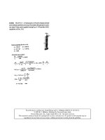
Stop the r
otor and add a trial weight to the part. The trial
weight should produce a force equal to 10% of the static
weight of the rotor on one bearing. Record the amount of
the trial weight (in ounces or grams) and the distance from
the centerline of rotation (in inches or centimeters). Insure
that the trial weight is firmly attached to the rotor.
where:
Trial weight = ounces in English system or grams in metric system
F = 10% of the static rotor weight (pounds in English system or
kilograms in Metric system)
R = radius of the trial weight from the centerline of rotation (inches in
English system or centimeters in Metric system)
N = rotor speed/1000 (RPM/1000)
K = 1.77 (English system) or 0.011 (Metric system)
Trial weight =
K x R x N
2
F
Weight Amount
Angular Location
4
90
oz.
degrees
0
30
60
90
120
150
180
210
240
270
300
330
+
TW
“Trial Weight”
Installation
?
Suggested Trial Weight Amount = 2.57 oz.
OK
Stop the machine and install a trial weight on the rotor.
Enter the trial weight amount and angular location.
To operate this window . . .
7.
Single plane balancing procedure
Piotrowski / Shaft Alignment Handbook, Third Edition DK4322_A001 Final Proof page 786 29.9.2006 7:46pm
786 Shaft Alignment Handbook, Third Edition
Restart the machine and operate the rotor at the
balancing speed. Observe and record the new unbalance
amplitude and phase data. This will be called the “original
plus trial weight” vector (O+T).
“Trial Weight” run
vibration amplitude and
phase angle data
Amplitude
Phase Angle
0.8
30
in/sec
degrees
0
30
60
tach
90
120
150
180
210
240
270
300
330
+
vibs
TW
OK
To operate this window . . .
Re-start the machine with the trial weight on the rotor.
Enter the vibration amplitude and phase angle data.
8.
Single plane balancing procedure
Piotrowski / Shaft Alignment Handbook, Third Edition DK4322_A001 Final Proof page 787 29.9.2006 7:46pm
Appendix K 787
On a sheet of polar graph paper, plot the “original run vector” (called
the “O” vector, the “original plus trial weight vector” (called the “O+T”
vector). Construct the “trial weight effect” vector (aka the “T” vector)
by connecting the ends of the “original” and “trial weight” vectors. The
“T” vector should point from the “O” vector to the “O+T” vector.
9.
0
10
20
30
40
50
60
70
80
90
100
110
120
130
140
150
160
170
180
190
200
210
220
230
240
250
260
270
280
290
300
310
320
330
340
350
*Notice that the
angular shift from
the “O” vector to the
“O+T” vector was a
counterclockwise
shift.Therefore,
the correction
weight should be
placed ina
clockwise
direction from its
trial weight position
(57 + 90 = 147).
“T” vector
0.59 ips at 57Њ
57
o
“O+T” vector
0.8 ips at 30Њ
“O” vector
0.5 ips at 120Њ
Single plane balancing procedure
Piotrowski / Shaft Alignment Handbook, Third Edition DK4322_A001 Final Proof page 788 29.9.2006 7:46pm
788 Shaft Alignment Handbook, Third Edition
Using a protractor, measure the included angle between the “O”
and “T” vectors. This will be called the “correction” angle
.
Mark the spot where the trial weight is located and remove the trial
weight. Install the correction weight at an angular amount equal to the
“correction” angle from the point where the trial weight was located but
in a direction opposite of the phase shift from the “O” vector to the
“O+T” vector. Make sure the correction weight is installed at the same
radius from the centerline of rotation as the trial weight.
14.
In the future, if you place the vibration and phase angle sensors in
the same place, all you need do is measure and record the amplitude
and phase angle data, plot it on a new piece of graph paper as the “O+T”
vector along with the “O” vecor, draw a new “T” vector, plug it into the
correction weight formula above and you have the new correction weight
y
ou need. Good luck and
g
reat balancin
g
!
Correction weight = trial weight ×
“original” vector amplitude
“trial weight effect” vector amplitude
Weight Amount
Angular Location
2.1 oz.
147 degrees
0
30
60
90
120
150
180
210
240
270
300
330
+
CW
The trial weight must be removed and the above weight
should be added at the angular location shown.
“Correction Weight” Information
Measure the length of the “trial weight effect” vector and use the
formula to determine the correct balance weight needed
10.
11.
12.
Run the rotor again and record the vibration and phase angle data.
If everything went OK, the rotor should now be balanced. If additional
“trim balancing” is required,use this latest amplitude and phase data
as a new “O+T” vector and plot it on a new polar graph paper along
with the original “O” vector. Draw a new “T” vector and re-calculate the
new correction weight. Repeat as often as necessary.
13.
Single plane balancing procedure
Piotrowski / Shaft Alignment Handbook, Third Edition DK4322_A001 Final Proof page 789 29.9.2006 7:46pm
Appendix K 789
Piotrowski / Shaft Alignment Handbook, Third Edition DK4322_A001 Final Proof page 790 29.9.2006 7:46pm
Index
A
A-Line systems 274–275
A-String
sheave alignment 605–606
accelerometer 40–41
Acculign system 486–487
Accushim, Inc. 274–275
Accushim systems 273
adhesive backed targets 511
adjusting belt tension 595–596
air gap clearance problems 703
air gap measurements 703–705
aligning bent shafts 8, 201
aligning two hollow cylinders 622–626
aligning vertically oriented rotating
machinery 249
alignment
history of 735–751
alignment accuracy 344
alignment and coupling tolerances 341–352
alignment bars 515–522
alignment bars with proximity probes
515–522
alignment certification 26–31
alignment laws
of multiple element drive trains 564 –566
alignment modeling 319–339, 347–348, 354,
606–612, 655, 697, 703
cardinal rules 361
for 3 bearing machines 703–705
for barrels and cylinders 622
for vertical generators 707–719
of multiple element drive
trains 588–589
of parallel rolls 639–640
of vertical pumps 678–679
to center rotors in housing 668
alignment qualifications 26–27
alignment records 2, 33
alignment skills 19–23
alignment skills testing 19–23
alignment software 273–274
alignment solutions 319, 567
alignment steps 7
alignment survey 2–3
alignment tolerances 7, 14, 17–19, 52, 53, 135,
138, 220
factors affecting 345
alignment tools 277–280
alignment training 12–13
alignment troubleshooting 311–315
allowable lateral movement envelope 336
finding 336
allowable lateral restrictions 321
allowable movement envelope 334–337, 565
allowable movement map 304
alternating current electric generator 702
anchor bolts 102–103, 109–111, 114, 118, 126
protecting 112–113
angular measurements
definition of . . . 343
angular misalignment 342
antifriction bearings 296
API Spec 686 118
arcsecond 341, 626
artificial face surface 385–387
asymmetrical bracket 363
axial distance 297
axial float 376, 379
axial flow compressor 481, 673
axial movement 155, 376
axial position 186, 296
axial spacing 296–297
axial spacing for a gear coupling 298
B
backside face readings 462
balance 144
in gear coupling 140–150
balancing 23, 424
balancing rotors 19
ball mill drive 563
Ball–Rod–Tubing connector system 476, 531, 545
barrel alignment 619–622
baseline data 19
basement floor 334–335
baseplates 89–91, 98–100, 109–110, 129
cast 92, 109–110, 128
checking 313
distortion of 94, 99, 118, 126
Piotrowski / Shaft Alignment Handbook, Third Edition DK4322_C023 Final Proof page 791 28.9.2006 11:01am
791
fabricated 92–110
grinding 19, 567
intentional distortion 99, 495
interface problems 179
levelling 118
levelness of 342
preparation 111–112
problems with 17
stress relieve 99
baseplate restriction point 334 –335
basic alignment models 321–323
beam dispersion 414
bearing
skidding or spinning 182–183
bearings
overheated 4 –5
bearing alignment 619
bearing loads 19, 496
bearing pedestals 693, 703–704
belt drives
advantages & disadvantages 591
alignment of 591–618
belt length
calculating 595–596
belt tension 591, 593, 595–596
belt tension gauge 595–596
belt wear indicator 594
Benchmark system 276
bending stresses 314, 389
biogas compressor 698
biogas engine 673
blowers
alignment considerations for 692–697
blue check 184
boiler feedwater pump 298
bolt bound 53, 292, 336, 423, 554
bolt bound conditions 292–294, 336, 419 , 655
modeling of 419–420
bore alignment 619–638
using Double Radial method 679
bore sighting targets 622–623
boundary conditions 634 –635
bracket=bar sag 267–269
bracket sag 253, 267–269, 315, 325–326, 654
compensating for 326
brass shims 300
bucking in 631–638
bucking in process 631–638
C
C-flanged motors 678
carbon steel shims 300
Cardan error 153, 653
case distortion from thermal expansion 490
catenary curve 349–350, 703, 740
CCD 241–245
cement 104 –105
centrifugal pumps 674, 674, 691–692
alignment considerations for 674–678
chainfalls 133, 306, 706
chain couplings 140
charge-coupled device 244, 316
chiller 698, 702
chiller compressor 698, 702
Christmas tree brackets 269
clutch 20, 489, 719
coefficients of thermal expansion 477– 478
coincidence level calibration test, aka Peg
Test 234, 509
collimate 647
collinear
definition of 344
comealongs 306
compensated readings 268
compensate for axial movement
during alignment 376
compressor 472
compressors 701–702
alignment considerations for 698–701
concrete 104–105
compressive strength 98, 104–105
curing 99, 104–105
time to cure 291
vibrators 99
Condition Based Maintenance 35–37
cone of runout 714
cone orbit diameter
in vertical generators 714
continuous lube oil system
in gears 719
converting vibration units 45
cooling tower fan drive 722–724
alignment considerations for 727
coordinate optical micrometer 622
coplanar
definition of 639–641
corrective moves 319, 332–333, 425, 586
coupling 153, 344
flexing points 345–347, 722–723
maximum misalignment tolerance 137–138
couplings
continuous oil feed 163
design criteria 138–139
disk=diaphragm 75, 147
elastomeric 156–158, 164
flexible & rigid 137–139, 591
history of 137
hydraulically installed 172–173
Piotrowski / Shaft Alignment Handbook, Third Edition DK4322_C023 Final Proof page 792 28.9.2006 11:01am
792 Shaft Alignment Handbook, Third Edition
hydraulic expansion 172–175
installation of 173–174
interference fits 168–170
keyless taper bores 172
lubrication of 140
mechanically flexible 74
miniature 139–141
removal of 170, 175
role of 138
thermal expansion for installation 169
thermal or hydraulic expansion 172–174
tolerances of 137–138
types of 75, 78
windage 518
coupling alignment 348
coupling bolts 314
coupling hub
contact pressure 173
slippage 172–173
coupling hub surface contact 171–172
coupling lockup 297
coupling tolerances 138, 348–349
crankshaft 673–774
cubit 735
curved axis of rotation 350
custom shims 300
cutlass bearings 188
cutting shims 300
cylinder alignment 627–631
D
Damalini Systems 416–418
damping 39– 40
desired off-line positions 315, 476
desired off-line shaft positions 540–548
dial indicator 134, 180–181, 187–188, 205, 212
basic operation of 180
inventor of 744, 751
dial indicator manufacturer pricing,
specifications, and features 284–285
diaphragm couplings 75, 158–159
diesel engines
for generators 703
die penetrant checks 192
disc couplings 161
Doppler effect 244
Double Dial method 353
Double Radial Method 389–395, 679
for bore alignment 620–622
Double Radial method
for vertical pumps 391–392
Double Radial Method mathematics 392
Double Radial shoot for dial indicator
readings 548
dowel pin 490
dowel pins 721–722
downward movement envelope 334
dredge drive shaft 188
drive shaft 197, 397–398, 406–407
drive train 48, 324, 341–345, 588–590
droop
in jackshaft 707
drop-in puller devices 307–309
dual beam–dual detector 412–413, 416, 418
dual scaling 406, 582
dual spirit level 248
dynamic forces 37–39, 194
E
eccentricity 194, 200–201
edge contact 203
elastic bending of shafts 52, 252–253
elastomeric coupling
excessive wear 193–194
electric generators
alignment considerations for 702–705
early history 742, 744
electric inside micrometer 709–710, 714
electric motors 186
alignment considerations for 668–670
electromagnetic forces 668
electromagnetic spectrum 238–239, 244
early history 739
electronic and electo-optical Shaft Alignment
Systems 411–426
Emerson Process Management system 418
energy loss due to misalignment 78
English System
origins of 737
estimated time to failure 5–6
exciter 563
extruder 619
extruder alignment 226–227
F
Face–Face method 321, 405–410
mathematics 407
Face–Face shoot for dial indicator readings 548
face–peripheral method 369, 377
Face–Rim mathematics 376
Face and Rim Method 369–387
Face and Rim modeling 376–385
Face–Rim shoot for dial indicator readings 548
face runout 598–599, 714
fans
alignment considerations for 692–697
fan blade to shroud clearances 693
Faraday, Michael 742
Piotrowski / Shaft Alignment Handbook, Third Edition DK4322_C023 Final Proof page 793 28.9.2006 11:01am
Index 793
feeler gauges 211, 171, 188, 191, 207, 212
FFT analyzer 44 –45
field readings 268–269
final desired alignment line 333, 337–338
financial loss 2, 181
finding the centerline of rotation 40, 70,
98, 118, 382
finite element analysis 89
fire pumps 673
FixturLaser systems 418–420
flatness 96, 227
definition of 342
flexible coupling 5, 46–47, 406
excessive misalignment 5, 71–74,
496, 671
flexible link coupling 152-3–154
floor targets 648
fluid drive 490, 719–720
fluid drives
alignment considerations for 719–720
foot bolts 15, 202, 211–212
considerations during installation 94,
foot plane compensators 217
foundations 9, 20, 33, 89–90, 40, 50,
59, 129, 404
attached to concrete floors 100–102
checking 89, 134
design basics 97–98
soil conditions 89–90
foundation bolts 2, 134, 301
frames 95–97
machinery 90, 732
frequency 96, 98
frequency domain 44–46
frequency range of vibration sensors 40, 44
fringe 244–245
G
gas=power turbine 672–673
gas turbine 18, 479, 672–673, 702
gas turbines
alignment considerations for 673
gearboxes
alignment considerations for 719–722
gear coupling
excessive wear 193
gear couplings 140–151
gear tooth clearances 140, 164
tilt & pivot positions 146
worm-tracking 146 –147
generator 71–72, 350, 719, 742, 744
graphical shaft alignment 321–323
grease
separation of in couplings 162–163
grout 104
epoxy based 111–118
mixing epoxy based grouts 104–105
pouring 108, 121
shrinkage 110
thermal reaction 104
time to cure 291
voids 109
grouting
methods 105–109
H
Hamar systems 420–421
high spots 682–683, 713–714
hollow feet 210
horsepower
history of 739
hot alignment measurements 473–474
hot and cold alignment 345
hot operating alignment
alignment modeling 548–560
hot operating position 541–542
hydraulic clutches 719
hydraulic jacks 306
hydraulic or mechanical shear
for fabricating shims 301
hydroelectric generators
alignment considerations for 707–708
I
inch
origins of 737
inclinometer 481, 487
Indikon 538–539
inertia block 103–104, 179, 291
infrared radiation
categories 479–481
infrared thermographic equipment
479–481
infrared thermography 71–77, 670
infrared thermometer 477
inside micrometer 166, 481–489
installing new machinery 291–292
instrumented coupling system 477, 438, 439
instrumented coupling systems 538–539
intentional centerline offset 405
interferometer 243–244
inventor of 744
internal combustion engines
alignment considerations for 673–674
internal machinery clearances
modeling=graphing of 324–325
internal rubs
due to rotor distortion 677–678
Piotrowski / Shaft Alignment Handbook, Third Edition DK4322_C023 Final Proof page 794 28.9.2006 11:01am
794 Shaft Alignment Handbook, Third Edition
Invar 228, 482, 486
Invar extension rod 511
J
jackscrews 18, 94, 99–100, 110, 114,
118, 303–304,
jackshaft 397–398, 405, 707, 722
Jig Transit 95, 114, 124, 641–644, 646
journal type bearings
alignment considerations 374
K
keys and keyways 165–167
key fits 166–167
kiln drive 563
L
labyrinth seals 192
lantern ring 190
laser 235–238
laser alignment systems
used on multiple element drive 420
for V-belts & sheaves 613–618
laser bore alignment systems 625, 638
lasers–detectors 252, 416
laser-detector OL2R mounts 526–527
laser-detector systems for OL2R 522–531
laser–detector systems 522–531
measuring parallelism 651
lasers
basic operation of 238–239
lasers & masers
inventors of 747
lasers and detectors 220, 235–238
laser interferometers 220
laser shaft alignment 20, 412, 421, 523
laser shaft alignment measurement system 220,
238, 316, 412, 426
laser system hardware comparison chart 429,
433–445, 447
laser system manufacturers hardware
specifications 426–468
laser system manufacturers software
specifications 444 –468
laser system software comparison chart 449–468
lateral movement boundaries 586
lateral movement envelope 336
lateral movement restrictions
335–337, 548, 577
lateral offset 303
lathe
using one for checking sag 269
leaf spring couplings 154
Leonardo da Vinci 737
level
definition of 341
history of 739
leveling 118, 126
soleplates 342
leveling optical instruments 499–501
levelness
guidelines 501
lifting jackscrews 304
light diffraction 241
light emitting diode 235, 238
light source
for optical alignment 124, 641
linear variable differential transformers 233–235
line shafts 342
Line to Points Reverse Indicator modeling
568, 575–576
lip seals 192
load ranges of typical soils 90
low spots 598
M
MAC10 system 411–412
Machinery Alignment Plotting Board 385, 387
machinery positioners 307
machinery positioning basics 296
machine case thermal expansion 28, 30,
476, 477, 541
machinist level 95, 100
magnetic base holders 228, 500, 512
magnetic center 138, 186, 296, 668
maintenance philosophies 35, 181
mass 39–41, 45, 70, 98, 101–102,
104 –105, 730, 739
maximum misalignment deviation
determining 339
finding 449
maximum offset 346
measurement errors
with coupling engaged 252
measurement tools
electronic 220–243
mechanical 220, 224–225, 238
mechanical packing 190
leakage of 189–190
mechanical seals 190, 202, 677
metal ribbon couplings 151
meter
origins of 737
Metric System 220
origins of 737
metrology 244
MG sets 563, 703
Michelson interferometer 244
Piotrowski / Shaft Alignment Handbook, Third Edition DK4322_C023 Final Proof page 795 28.9.2006 11:01am
Index 795
micrometer 27–30, 118, 165–166, 220, 223–239,
314, 374, 431, 439, 447, 451, 456, 463, 476,
481– 487, 492–495, 500–501, 506–509, 513,
529–532, 541, 622, 624, 629–632, 638,
709–717, 739, 742–743
early history 223–225
mils=inch 346
misalignment
moderate 3, 21, 32, 48, 193, 225, 252–253, 314,
389, 677, 674, 670, 678, 701
responsibility 23–25
severe 3–6, 20, 55, 131–132, 137–138, 193, 225,
252–253, 314, 338, 389, 669, 679, 686
slight 3, 5, 48, 55, 183, 321, 341,
377–378, 568, 600
misalignment tolerance
calculating the 452–454
Misalignment Tolerance Guide 138, 346–347
modeling the Double Radial Method 393
modeling the Face–Face Method 284–286
modeling the Shaft to Coupling Spool
Method 284 –285, 321, 397–400, 405,
553, 557, 654, 723
molecular vibration in materials 477
monuments 648
motor-generator set 350, 565
motor-generator sets 350, 565
motors
alignment considerations for 472, 667
motor generator set 350, 565
movable machine 19, 24, 411, 416, 425
movement envelope 294, 334, 336–337, 446–447,
451, 456, 463, 468, 565, 567, 611
movement map 304
movement restrictions 18, 319, 322, 332, 334–337,
548, 553–557, 586–587, 590, 654–655
multiple element drive systems
alignment of 420, 424, 563
multiple element machine drive trains
304, 417–418
multiple stage compressor 565
multistage compressors 698
Murray & Garig system 276
N
natural frequency 89, 96, 98, 159
NEMA foot pad specifications 293
NEMA motor frame sizes 300
nozzle loads 671
O
off-line to running conditions 16, 20, 98
typical machinery where this is likely to
occur 324
off-line to running machinery movement 26, 43,
78, 99, 405, 471, 473, 530, 748, 750
surveys 43
off-line to running movement 430, 438
offset aligning rotating machinery shafts 548
OL2R 473
OL2R measurements
categories of 474
OL2R movement
in the axial direction 489
OPTALIGN 422–423, 435–436, 450, 452–454
optical alignment 27–28, 30, 99, 220, 226, 477,
451, 456, 463, 641, 651
early history 124, 128–129, 739
for OL2R measurements 476, 499, 512–513,
540–541
of hollow cylinders 638
optical alignment tooling 27, 28, 30, 220, 226
optical encoder 17, 27, 220, 235, 238, 313, 316,
320–321, 411, 437, 468, 750
optical horizontal measurements, aka waving
scales 513–514
optical micrometer 226, 228, 231–232, 234, 500,
506–507, 509, 513, 622, 624, 629–632, 638
optical parallax 229, 502
optical scale target 114, 118, 124, 228–229, 232,
500, 505, 507, 512–514, 644, 660
optical tooling level 227, 499, 504
overlay line 319, 325, 333–339, 354, 383, 448, 453,
457, 464, 530–532, 548, 554, 567, 577–578,
697, 699, 704 –705
P
packing gland 190, 691
paper machine 342
parallel alignment 639
partial arc mathematics 225
partial rotation of shafts
alignment trick 726–727
peel away shims 216
peg test 229, 234, 501, 509, 512–513
pentaprism 414, 651–652
Permalign system 525, 530
permanent floor target 519, 648
permanent jackscrews 307
perpendicularity checks
for rabbeted fits 691
Peterson Alignment Tools Co. systems 277
phase angle 41–42, 47, 51
photodiodes 235, 238, 240–243, 411, 412–414,
422, 429, 431, 433, 435, 437, 441, 529, 617,
625, 638, 651–652, 660
basic operation of 238
photonics 238
Piotrowski / Shaft Alignment Handbook, Third Edition DK4322_C023 Final Proof page 796 28.9.2006 11:01am
796 Shaft Alignment Handbook, Third Edition
phototach 42, 47
pi 343
piano wire 709–710, 717, 730
PIBZLT system 527, 529, 532
pillow block bearing 202, 212–215, 586
pintle pin 724–733
pin drive coupling 155–156
piping
considerations during installation 381
effect on alignment 338–339
support structures 383
thermal expansion or contraction 598
piping connections 324
piping fit-up problems 338
piping stress 15–16, 19, 32–33, 134–135
test 14, 15, 18, 32
piping supports 23, 89, 131
pitfalls of partial arc measurements 266
plastigage 183–185, 214–216
plug in back zeroing laser-target mounts 525, 527
plumb
in vertical generators 709, 711–719
plumb bob 709, 717
points of power transmission 1, 344–348
Point to Point Reverse Indicator modeling
355, 568
portable jackscrews 307
portable jack bolt kits 307
Portland cement 104, 111, 742
Posi Lock
undercut bolts 295
Posi Lock Puller 295–296, 311–312
power loss
from misalignment 78
power turbines 673
Precision Brand Products, Inc. 299
precision vertical lift 622
precut U-shaped shims 214, 299–300
precut U shaped shim stock 299, 334
predictive maintenance 5, 10, 23, 36
pregrouted baseplates 110
preliminary alignment checks 179–218, 597
preventive maintenance 36–37, 181
pro-active=prevention maintenance
10, 35, 37, 181
pro-active maintenance 10
proximity probes 42–44, 47–50, 53,
80, 237
proximity probes with water cooled stands 27–28,
30, 476, 497, 541
Pru
¨
ftechnik systems 548–552
pry and crow bars 305
PSD
Position Sensing Device 414, 439
pumps
early history 14
pyramid tooling ball mathematics 493
pyramid tooling ball set up 491
Q
quanta 239, 745
R
R2OL 473, 478, 482, 485, 514, 518, 529, 533, 538
rabbeted fits 678, 691
concentricity and perpendicularity checks 691
radial bearing clearance range 183
radial runout 194, 199–200, 701, 714, 716–717
radians 49, 262–263, 343
reactionary moments 473
reciprocating compressor 698, 701
reference planes 510
reference transit 647–651
reflected beam principle 412
reinforced concrete 97, 105, 107
reliability engineering 10
resonance 240
in couplings 161
restriction rings 586
Reverse Indicator mathematics 357
Reverse Indicator Method 278, 284–285, 331,
353–366, 369, 411, 416, 418, 424 –425,
445–446, 451, 455, 515, 543, 749
used on multiple element drive 362
Reverse Indicator set up variations 355
Reverse Indicator shoot for dial indicator
readings 543–547
right angled gear 563, 583, 585–586
right angled gearbox 403
right angle drive 578–585
alignment modeling 583–584
rigid coupling
in vertical pumps 678–680
spigot fit 703
rigid couplings 137–175, 161–162, 219, 252–253,
319, 342, 389, 706
rigid coupling alignment 162
rim measurements 247, 384, 549–550
ring laser gyroscope 652, 659
rolling element bearing
design 181–183
problems 181
roll parallelism 226, 228, 500, 639, 641, 653
roof prism 412, 414, 421, 422
rope stretcher 220
rotating shafts
precautionary measures 172
rough align 17, 204, 221
Piotrowski / Shaft Alignment Handbook, Third Edition DK4322_C023 Final Proof page 797 28.9.2006 11:01am
Index 797
RTD’s 477
rudder alignment 730
rulers 220–221
rules of thumb
for shims 301
running shaft misalignment 137
running shaft positions 541–542, 548, 554
runout 40, 41, 52, 56, 59, 261–269, 300, 404, 735
acceptable limits 714, 717
alignment considerations for 679, 680, 682,
688–689, 691, 697, 709–717
how to check 194 –195
on sheaves 199, 597
on vertical pumps 161–162, 195–197,
679–680, 686
overriding 249–251
types of 194 –195, 200–201
why measure? 255, 639, 679
runout guidelines
for sheaves 199, 597, 639,
S
safety 14, 16–18, 78, 158, 186, 306, 429, 432–433,
435, 437, 439, 473–474, 538, 668, 739
scaling factors 321
seals 1, 5, 9, 35, 37, 137–139, 162–163, 179,
189–192, 202, 217, 291, 349, 677, 709, 711
see through target 623–624, 628
seismometer 52
early history 742
semiconductors 238
severe misalignment 3, 20, 132, 193, 252, 389
shafts
elastic bending of 5, 52, 252, 351, 389
shafts elastically bend due to the misalignment
condition 406
shaft alignment
measuring tools 219–287, 316, 319
shaft alignment measurement system 238, 313,
314, 343, 412, 416, 473
shaft alignment patents 176, 405
shaft bending 1, 253
shaft expansion 625
shaft fretting 164, 168
shaft hunting 668
shaft lift check 181, 187
shaft misalignment
definition of 201, 319, 343–347
shaft seals 190, 202
shaft sleeve 190
Shaft to Coupling Spool Method 284–285,
397–403, 414, 517–526, 553, 577, 654, 723
mathematics 400
used on multiple element drive 721
Shaft to Coupling Spool shoot for dial indicator
readings 548
shaft to shaft distance 668, 673, 681, 726
sheave 591, 593–594, 604 –613, 615
runout 199, 597, 599–603, 639, 697
sheaves
centerline offset 607
sheave and belt wear 594
sheave misalignment 593, 599, 604
offset, pitch, and skew 597–599
sheave standards 591, 595
shim sandwich 216–217, 301
shim stock 129, 179, 203, 209, 214, 216,
221, 225, 296, 298–301, 309, 316,
333–335, 432, 434
shim thickness 299, 552, 554
ship rudders
alignment considerations for 724–733
shoot-for dial indicator readings 32, 447, 452, 456
sighting target fixture 624–625
sine wave
generated during alignment
measurements 258–267
single beam-dual detector using beam
splitter 413, 433
Sixteen Point Method 370, 377
sleeved bolts 496
slide caliper 223–224, 739
sliding bearings 185, 187, 669
sliding fits in couplings 225
sliding type bearing 40, 80
clearance 181–186
design 182–183
tilt and twist checks 184
sliding type bearings 43, 46, 71, 80, 183, 188, 296,
668, 672
sliding type radial and thrust bearings 296
slight misalignment 3, 5
slump test 104
snap gage 165, 191, 374, 377–378
soft foot 2, 8–9, 14 –19, 24, 29, 32–33, 128–129,
208, 215, 221, 301, 313, 333–335, 342,
415–416, 419, 424, 597, 670–671, 673–674,
677, 686, 697, 701, 705, 720–721
correction shims 206, 211, 213, 216
introducing one during alignment 202, 218
in pillow block bearings 202, 212–215
lift 207, 213–214, 216, 724 –725
on C-flanged motors 678
soft foot example 208
soleplates 91, 94–95, 98, 102, 105, 108–109, 130,
291, 242, 674–675, 722
levelness of 95, 98
spectrum analyzer 44
Piotrowski / Shaft Alignment Handbook, Third Edition DK4322_C023 Final Proof page 798 28.9.2006 11:01am
798 Shaft Alignment Handbook, Third Edition
spherically seated bearings 184, 186
spinning zeros 268, 315
splined shaft 165, 170–171
split coincidence level 229, 234–236,
501, 510–511
split collar
for runout checks 688–691
SPM Instrument Inc. System 424 – 426
squareness 227–228, 500
squaring work pieces in lathes 369
stainless steel shims 300
stall=surge
in compressors 701
static forces 37, 39, 66, 71
stationary–movable alignment 337
steam engine
early history 740, 742
steam turbine 18, 130, 184, 195–196, 670–672,
703, 721, 736, 739, 743–744
steam turbines
alignment considerations for 670–672
early history 744
for generators 350, 563, 703
stiffness 39–40, 45, 92, 103, 155, 161, 268, 350
straight edge 639
strain 477
strobe light 41, 42, 47, 515, 536–537
structural dynamics 89
structural mode shapes 89
stub shaft 197–199
stuffing box 190–192, 680–681, 683
concentricity of 191
surface profile 118, 200
sway bar
on steam turbines 130
symmetrical bracket 363
symptoms of misalignment 1–3
T
tapered shaft ends 170
taper gauges 220–222, 377–378
taper lock bushing 220–221
tape measures 220–221
target values 448, 453, 457, 542
T bar overlay 377, 382–385, 406, 408, 410, 548,
606–608, 681–683, 716
telescope
early history 737, 739
Telescopic Transit Square 641–643, 646
theodolite
early history 736, 740
theodolite system 476
thermal expansion 134, 169, 228, 447, 452, 456,
472, 476–478, 481–482, 490, 500, 541, 719
thermal strain equation 477
thermocouples 477
thermometer
early history 739
threaded coupling 197, 686–688
thrust bearing 43, 186–188, 296, 390, 668, 672,
678, 707, 709, 712, 714, 717
thrust bearings 129, 187, 296, 376, 379, 672
thrust bearing clearance 187–188, 296
thrust float 672
tight wire 729–731, 751
tilting level 227, 235–236, 508, 510–513
tilt pad bearing 187–188
time domain 46, 50–51
tin snips 206, 300
toe down 203
toe up 203
tooling ball 447, 451, 456, 476, 481– 495, 511, 519,
527, 531–532, 541
torsional counter reaction 673
translation slide 622, 641, 649
translucent optical target 644
transverse keys 490, 496
triangular tooling ball mathematics 492
triangular tooling ball set up 491–492
turbine generator 350, 352, 378, 707, 718
Turvac Inc. systems 279
Twenty Point Method 371–374, 378
types of misalignment 343, 599
types of movement tools 304–307
types of shaft seals 190
U
undercut bolt 294–296
undercut bolts 295
universal joint
early history 152–153, 736
universal joint coupling 152
Update International system 282
V
V-belt 51, 70, 416, 591–597, 604–613
alignment modeling 606, 612, 655, 697, 703
guidelines 593–597
standards 591
V-belt drives
alignment of 591–617, 613
vacuum draw down 671
validity rule 253–254, 257, 266, 331, 536
vehicular drive shaft 397
vernier–strobe method 477, 750
Vernier–Strobe system 30, 447, 451, 456, 535–536
vernier caliper
early history 537
Piotrowski / Shaft Alignment Handbook, Third Edition DK4322_C023 Final Proof page 799 28.9.2006 11:01am
Index 799
vertical generators
alignment considerations for 707–719
vertical movement restriction 335
vertical pump 56, 161–162, 195, 197, 389, 546,
549, 678, 680
vertical pumps
alignment considerations for 678–679, 686
Vibralign system 425, 439–440
vibration 3, 20, 23, 36, 40–45, 50–58, 65–66,
68–80, 89, 95–96, 98–99, 102–103, 130, 153,
182–183, 192, 232, 344, 477, 515, 669, 678
diminishes with misalignment 38–39, 46–49
due to runout 194, 691, 697, 714
due to soft foot 14, 24, 202, 670, 697
engineers & technicians 7, 14, 24 –25, 89,
from misalignment 2, 46, 52–54
in sliding bearings 669
signatures 45–47, 58, 71
spectrum 7, 44, 46, 51
transmitted to surrounding area 98
vibration amplitude 40, 44, 48, 95
vibration sensors 40, 233
videometry 476
W
water cooled pipe stands 511
water turbines
early history 740
web deflection test 674
wedges 32, 99, 206–207, 212, 218, 221,
305, 316, 390
wedge shaped shims 203, 214
Whitworth system 224
Z
zero sag brackets 271
zinc based primer 107
Piotrowski / Shaft Alignment Handbook, Third Edition DK4322_C023 Final Proof page 800 28.9.2006 11:01am
800 Shaft Alignment Handbook, Third Edition
Reinforcement rods
Concrete foundation
soil
Grout
Baseplate or
soleplate
Pipe (allows for slight
anchor bolt adjustment)
Nut (see alternative ways for leveling)
Frost line
75% of total
pedestal
height
Anchor bolt
imbedded in
concrete
Concrete
Isolation matting
(if desired)
Protective sleeve
FIGURE 3.12 Section view of a typical rigid foundation.
Piotrowski / Shaft Alignment Handbook, Third Edition DK4322_Plates Final Proof page 1 6.10.2006 5:37pm
10 in.
0.010 in. (10 mils)
Final pregrout surface
elevation and profile
Up
Side view
Pump
Steam turbine
17.800 in. 17.797 in.
17.803 in.17.812 in.
17.833 in. 17.832 in.
17.840 in.17.840 in.
17.787 in.
17.799 in.
17.800 in.
17.788in.
17.807 in.
17.808 in.
17.796 in.
17.793 in.
0.802 in. 0.809 in.
0.810 in.0.802 in.
0.802 in. 0.800 in.
0.801 in.0.806 in.
0.806 in. 0.811 in.
0.811 in.0.807 in.
0.800 in. 0.799 in.
0.802 in.0.803 in.
Bolt plane
Bolt plane
Bolt plane
Bolt plane
Bolt plane
Bolt plane
Pad A
Pad B
Pad C
Pad D
Pad E
Pad GPad F
Pad H
Pad A
Pad B
Pad C
Pad D
Pad E
Pad G
Pad F
Pad H
Notes:
• All elevation data was captured
with a optical jig transit
• Elevataions were taken on each
pad at all four corners
• The “shoot for” elevation at the
bolt was set at 0.800
in. for the
pump pads and 17.800 in. for the
turbine pads
North
Top view
Elevations
No. 15 BFW baseplate before grouting
0.800 in. (pump)
17.800
in. (turbine)
0.790
in. (pump)
17.790
in. (turbine)
0.810
in. (pump)
17.810
in. (turbine)
0.820
in. (pump)
17.820
in. (turbine)
0.830
in. (pump)
17.830
in. (turbine)
0.840
in. (pump)
17.840
in. (turbine)
View looking north
Surface with
south edge
higher
Surface with
north edge
higher
FIGURE 3.45 Baseplate elevation profile prior to grouting.
Piotrowski / Shaft Alignment Handbook, Third Edition DK4322_Plates Final Proof page 2 6.10.2006 5:37pm
10 in.
0.010 in. (10 mils)
Final pre and post-
grout surface elevation
and profile
Up
Side view
Bolt plane
Bolt plane
Bolt plane
Bolt plane
Bolt plane
Bolt plane
Pad A
Pad B
Pad C
Pad D
Pad E (before grout)
Pad G
Pad F
Pad H
Notes:
• All elevation data was captured
with a optical jig transit
• Elevataions were taken on each
pad at all four corners
• The “shoot for” elevation at the
bolt was set at 0.800 in. for the
pump pads and 17.800 in. for the
turbine pads
0.800 in. (pump)
17.800 in. (turbine)
0.790 in. (pump)
17.790 in. (turbine)
0.810 in. (pump)
17.810 in. (turbine)
0.820 in. (pump)
17.820 in. (turbine)
0.830 in. (pump)
17.830 in. (turbine)
0.840 in. (pump)
17.840 in. (turbine)
View looking north
Surface with
south edge
higher
Surface with
north edge
higher
Pump
Steam turbine
17.805 in. 17.799 in.
17.808 in.17.814 in.
17.859 in. 17.856 in.
17.862 in.17.865 in.
17.827 in.
17.839 in.
17.844 in.
17.831 in.
17.851 in.
17.851 in.
17.840 in.
17.836 in.
0.850 in. 0.857 in.
0.859 in.0.851 in.
0.821 in. 0.823 in.
0.827 in.0.817 in.
0.857 in. 0.859 in.
0.860 in.0.856 in.
0.823 in.
0.825 in.
0.826 in.
0.824 in.
Pad A
Pad B
Pad C
Pad D
Pad E
Pad GPad F Pad H
North
Top view
No. 15 BFW Baseplate after grouting
Elevations
0.850 in. (pump)
17.850 in. (turbine)
0.860 in. (pump)
17.860 in. (turbine)
0.870 in. (pump)
17.870 in. (turbine)
0.880 in. (pump)
17.880 in. (turbine)
0.890 in. (pump)
17.890 in. (turbine)
Pad F
Pump
Steam turbine
17.800 in. 17.797 in.
17.803 in.17.812 in.
17.833 in. 17.832 in.
17.840 in.17.840 in.
17.787 in.
17.799 in.
17.800 in.
17.788 in.
17.807 in.
17.808 in.
17.796 in.
17.793 in.
0.802 in. 0.809 in.
0.810 in.0.802 in.
0.802 in. 0.800 in.
0.801 in.0.806 in.
0.806 in. 0.811 in.
0.811 in.0.807 in.
0.800 in. 0.799 in.
0.802 in.0.803 in.
Pad A
Pad B
Pad C
Pad D
Pad E
Pad GPad F Pad H
North
Top view
No. 15 BFW Baseplate before grouting
Pregrout “shoot for” elevation
Post-grout best fit curve
Pad D
Pad B
Pad G
Pad C
Pad H
Pad E (after grout)
FIGURE 3.62 Elevation data and profiles before and after grout pour.
Piotrowski / Shaft Alignment Handbook, Third Edition DK4322_Plates Final Proof page 3 6.10.2006 5:37pm
Packing
Lantern ring
Packing gland
“Stuffing box” area
Rotating seal
Stationary seal
Spring
O-rings
Lip seal
Labyrinth seal
FIGURE 5.15 Four commonly used seals in rotating machinery.
Piotrowski / Shaft Alignment Handbook, Third Edition DK4322_Plates Final Proof page 4 6.10.2006 5:37pm