Industrial Machinery Repair Part Episode 1 Part 5 pot
Bạn đang xem bản rút gọn của tài liệu. Xem và tải ngay bản đầy đủ của tài liệu tại đây (382.35 KB, 25 trang )
84 Bearings
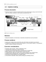
Air vent
Thrust bloc
k
Runner
Shoe
Mach. frame
Radial
bearin
g
Oil tight
joint
Self aligning
equalizing
base
Oil
retainer
Oil
level
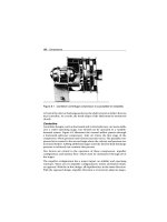
Figure 6.1 Half section of mounting for vertical thrust bearing
Radial or Journal
Plain radial, or journal, bearings also are referred to as sleeve or Babbit
bearings. The most common type is the full journal bearing, which has
360-degree contact with its mating journal. The partial journal bearing has
less than 180-degree contact and is used when the load direction is constant.
The sections to follow describe the major types of fluid-film journal bearings:
plain cylindrical, four-axial groove, elliptical, partial-arc, and tilting-pad.
Plain Cylindrical
The plain cylindrical journal bearing (Figure 6.2) is the simplest of all
journal bearing types. The performance characteristics of cylindrical bear-
ings are well established, and extensive design information is available.
Practically, use of the unmodified cylindrical bearing is generally limited
to gas-lubricated bearings and low-speed machinery.
Four-Axial Groove Bearing
To make the plain cylindrical bearing practical for oil or other liquid lubri-
cants, it is necessary to modify it by the addition of grooves or holes through
which the lubricant can be introduced. Sometimes, a single circumferential
Bearings 85
Load
Bearing
Clearance C
Journal
Diameter D
Figure 6.2 Plain cylindrical bearing
Load
Groove
Bearing
Clearance C
Journal
45°
45°
35° 35°
9°
Diameter D
Figure 6.3 Four-axial groove bearing
groove in the middle of the bearing is used. In other cases, one or more
axial grooves are provided.
The four-axial groove bearing is the most commonly used oil-lubricated
sleeve bearing. The oil is supplied at a nominal gauge pressure that ensures
an adequate oil flow and some cooling capability. Figure 6.3 illustrates this
type of bearing.
Elliptical Bearing
The elliptical bearing is oil-lubricated and typically is used in gear and tur-
bine applications. It is classified as a lobed bearing in contrast to a grooved
bearing. Where the grooved bearing consists of a number of partial arcs with
a common center, the lobed bearing is made up of partial arcs whose centers
86 Bearings
Load
Journal Radius R
Bearing
C = Clearance
m = Elli
p
ticit
y
Groove
R
15°
15°
Journal
mC
mC
R+C
R+C
Figure 6.4 Elliptical bearing
do not coincide. The elliptical bearing consists of two partial arcs where the
bottom arc has its center a distance above the bearing center. This arrange-
ment has the effect of preloading the bearing, where the journal center
eccentricity with respect to the loaded arc is increased and never becomes
zero. This results in the bearing being stiffened, somewhat improving its
stability. An elliptical bearing is shown in Figure 6.4.
Partial-Arc Bearings
A partial-arc bearing is not a separate type of bearing. Instead, it refers to
a variation of previously discussed bearings (e.g., grooved and lobed bear-
ings) that incorporates partial arcs. It is necessary to use partial-arc bearing
data to incorporate partial arcs in a variety of grooved and lobed bearing
configurations. In all cases, the lubricant is a liquid and the bearing film is
laminar. Figure 6.5 illustrates a typical partial-arc bearing.
Tilting-Pad Bearings
Tilting-pad bearings are widely used in high-speed applications where
hydrodynamic instability and misalignment are common problems. This
bearing consists of a number of shoes mounted on pivots, with each shoe
being a partial-arc bearing. The shoes adjust and follow the motions of the
journal, ensuring inherent stability if the inertia of the shoes does not inter-
fere with the adjustment ability of the bearing. The load direction may either
pass between the two bottom shoes or it may pass through the pivot of the
bottom shoe. The lubricant is incompressible (i.e., liquid), and the lubricant
film is laminar. Figure 6.6 illustrates a tilting-pad bearing.
Bearings 87
Load
Bearing
Clearance
C
Journal
Diameter D
A
r
c
L
e
n
g
t
h
Figure 6.5 Partial-arc bearing
Load
Ψ
Bearing Housing
Tilting Shoe
Clearance C
Journal
Diameter D
Figure 6.6 Tilting-pad bearing
Rolling Element or Antifriction
Rolling element antifriction bearings are one of the most common types
used in machinery. Antifriction bearings are based on rolling motion as
opposed to the sliding motion of plain bearings. The use of rolling elements
between rotating and stationary surfaces reduces the friction to a fraction
of that resulting with the use of plain bearings. Use of rolling element bear-
ings is determined by many factors, including load, speed, misalignment
sensitivity, space limitations, and desire for precise shaft positioning. They
support both radial and axial loads and are generally used in moderate- to
high-speed applications.
Unlike fluid-film plain bearings, rolling element bearings have the added
ability to carry the full load of the rotor assembly at any speed. Where
88 Bearings
fluid-film bearings must have turning gear to support the rotor’s weight
at low speeds, rolling element bearings can maintain the proper shaft
centerline through the entire speed range of the machine.
Grade Classifications
Rolling element bearings are available in either commercial- or precision-
grade classifications. Most commercial-grade bearings are made to non-
specific standards and are not manufactured to the same precise standards
as precision-grade bearings. This limits the speeds at which they can
operate efficiently, and given the brand of bearings may or may not be
interchangeable.
Precision bearings are used extensively on many machines such as pumps,
air compressors, gear drives, electric motors, and gas turbines. The shape of
the rolling elements determines the use of the bearing in machinery. Because
of standardization in bearing envelope dimensions, precision bearings were
once considered to be interchangeable, even if manufactured by different
companies. It has been discovered, however, that interchanging bearings
is a major cause of machinery failure and should be done with extreme
caution.
Rolling Element Types
There are two major classifications of rolling elements: ball and roller.
Ball bearings function on point contact and are suited for higher speeds
and lighter loads than roller bearings. Roller element bearings function on
line contact and generally are more expensive than ball bearings, except
for the larger sizes. Roller bearings carry heavy loads and handle shock
more satisfactorily than ball bearings, but are more limited in speed.
Figure 6.7 provides general guidelines to determine if a ball or roller
bearing should be selected. This figure is based on a rated life of 30,000
hours.
Although there are many types of rolling elements, each bearing design is
based on a series of hardened rolling elements sandwiched between hard-
ened inner and outer rings. The rings provide continuous tracks or races
for the rollers or balls to roll in. Each ball or roller is separated from its
neighbor by a separator cage or retainer, which properly spaces the rolling
elements around the track and guides them through the load zone. Bearing
size is usually given in terms of boundary dimensions: outside diameter,
bore, and width.
Bearings 89
Roller bearing
Ball or roller bearing
Ball
Shaft speed, rpm
Radial load, lb
Speed limit
6
10,000
1000
100
10 100 1000 10,0002 346 2 346 346
4
3
2
8
6
4
3
2
8
6
4
3
2
8
6
4
3
2
Figure 6.7 Guide to selecting ball or roller bearings
Ball Bearings
Common functional groupings of ball bearings are radial, thrust, and
angular-contact bearings. Radial bearings carry a load in a direction per-
pendicular to the axis of rotation. Thrust bearings carry only thrust loads, a
force parallel to the axis of rotation tending to cause endwise motion of the
shaft. Angular-contact bearings support combined radial and thrust loads.
These loads are illustrated in Figure 6.8. Another common classification
of ball bearings is single-row (also referred to as Conrad or deep-groove
bearing) and double-row.
Single-Row
Types of single-row ball bearings are radial nonfilling slot bearings, radial
filling slot bearings, angular contact bearings, and ball thrust bearings.
Radial, Nonfilling Slot Bearings
This ball bearing is often referred to as the Conrad-type or deep-groove
bearing and is the most widely used of all ball bearings (and probably of
90 Bearings
(a) Radial load (b) Thurst load (c) Combination load
Figure 6.8 Three principal types of ball bearing loads
Figure 6.9 Single-row radial, nonfilling slot bearing
all antifriction bearings). It is available in many variations, with single or
double shields or seals. They sustain combined radial and thrust loads, or
thrust loads alone, in either direction—even at extremely high speeds. This
bearing is not designed to be self-aligning; therefore, it is imperative that
the shaft and the housing bore be accurately aligned (Figure 6.9).
Figure 6.10 labels the parts of the Conrad antifriction ball bearing. This
design is widely used and is versatile because the deep-grooved raceways
permit the rotating balls to rapidly adjust to radial and thrust loadings, or a
combination of these loadings.
Radial, Filling Slot Bearing
The geometry of this ball bearing is similar to the Conrad bearing, except for
the filling slot. This slot allows more balls in the complement and thus can
Bearings 91
Width
Corner radius
Corner radius
Inner ring
ball race
Inner ring
Outer ring
Outside
diameter
Bore
Face
Separator
Outer ring
ball race
Shoulders
Figure 6.10 Conrad antifriction ball bearing parts
carry heavier radial loads. The bearing is assembled with as many balls that
fit in the gap created by eccentrically displacing the inner ring. The balls are
evenly spaced by a slight spreading of the rings and heat expansion of the
outer ring. However, because of the filling slot, the thrust capacity in both
directions is reduced. In combination with radial loads, this bearing design
accomodates thrust of less than 60% of the radial load.
Angular Contact Radial Thrust
This ball bearing is designed to support radial loads combined with thrust
loads, or heavy thrust loads (depending on the contact-angle magnitude).
The outer ring is designed with one shoulder higher than the other, which
allows it to accommodate thrust loads. The shoulder on the other side of
the ring is just high enough to prevent the bearing from separating. This
type of bearing is used for pure thrust load in one direction and is applied
either in opposed pairs (duplex), or one at each end of the shaft. They can be
mounted either face to face or back to back and in tandem for constant thrust
in one direction. This bearing is designed for combination loads where the
thrust component is greater than the capacity of single-row, deep-groove
bearings. Axial deflection must be confined to very close tolerances.
92 Bearings
Ball-Thrust Bearing
The ball-thrust bearing supports very high thrust loads in one direction
only, but supports no radial loading. To operate successfully, this type of
bearing must be at least moderately thrust-loaded at all times. It should not
be operated at high speeds, since centrifugal force causes excessive loading
of the outer edges of the races.
Double-Row
Double-row ball bearings accommodate heavy radial and light thrust loads
without increasing the outer diameter of the bearing. However, the double-
row bearing is approximately 60 to 80% wider than a comparable single-row
bearing. The double-row bearing incorporates a filling slot, which requires
the thrust load to be light. Figure 6.11 shows a double-row type ball
bearing.
This unit is, in effect, two single-row angular contact bearings built as a unit
with the internal fit between balls and raceway fixed during assembly. As a
result, fit and internal stiffness are not dependent upon mounting methods.
These bearings usually have a known amount of internal preload, or com-
pression, built in for maximum resistance to deflection under combined
Figure 6.11 Double row-type ball bearing
Bearings 93
Figure 6.12 Double-row internal self-aligning bearing
loads with thrust from either direction. As a result of this compression prior
to external loading, the bearings are very effective for radial loads where
bearing deflection must be minimized.
Another double-row ball bearing is the internal self-aligning type, which is
shown in Figure 6.12. It compensates for angular misalignment, which can
be caused by errors in mounting, shaft deflection, misalignment, etc. This
bearing supports moderate radial loads and limited thrust loads.
Roller
As with plain and ball bearings, roller bearings also may be classified by
their ability to support radial, thrust, and combination loads. Note that
combination load-supporting roller bearings are not called angular-contact
bearings as they are with ball bearings. For example, the taper-roller bearing
is a combination load-carrying bearing by virtue of the shape of its rollers.
Figure 6.13 shows the different types of roller elements used in these
bearings. Roller elements are classified as cylindrical, barrel, spherical,
and tapered. Note that barrel rollers are called needle rollers when they
are less than
1
4
" in diameter and have a relatively high ratio of length to
diameter.
94 Bearings
Spherical Cylindrical
Needle Tapered
Figure 6.13 Types of roller elements
Spherical Cylindrical
Needle Tapered
Figure 6.14 Cylindrical roller bearing
Cylindrical
Cylindrical bearings have solid or helically wound hollow cylindrically
shaped rollers, which have an approximate length-diameter ratio ranging
from 1:1 to 1:3. They normally are used for heavy radial loads beyond the
capacities of comparably sized radial ball bearings.
Cylindrical bearings are especially useful for free axial movement of the
shaft. The free ring may have a restraining flange to provide some restraint to
endwise movement in one direction. Another configuration comes without
a flange, which allows the bearing rings to be displaced axially.
Either the rolls or the roller path on the races may be slightly crowned to
prevent edge loading under slight shaft misalignment. Low friction makes
this bearing type suitable for fairly high speeds. Figure 6.14 shows a typical
cylindrical roller bearing.
Figure 6.15 shows separable inner-ring cylindrical roller bearings.
Figure 6.16 shows separable inner-ring cylindrical roller bearings with a
different inner ring.
Bearings 95
Figure 6.15 Separable inner ring-type cylindrical roller bearings
Figure 6.16 Separable inner ring-type roller bearings with different inner
ring
Figure 6.17 Separable inner ring-type cylindrical roller bearings with elimi-
nation of a retainer ring on one side
The roller assembly in Figure 6.15 is located in the outer ring with retaining
rings. The inner ring can be omitted and the roller operated on hardened
ground shaft surfaces.
The style in Figure 6.16 is similar to the one in Figure 6.15, except the rib
on the inner ring is different. This prohibits the outer ring from moving in
a direction toward the rib.
Figure 6.17 shows separable inner ring-type cylindrical roller bearings with
elimination of a retainer ring on one side.
96 Bearings
Figure 6.18 Needle bearings
The style shown in Figure 6.17 is similar to the two previous styles except
for the elimination of a retainer ring on one side. It can carry small thrust
loads in only one direction.
Needle-Type Cylindrical or Barrel
Needle-type cylindrical bearings (Figure 6.18) incorporate rollers that are
symmetrical, with a length at least four times their diameter. They are some-
times referred to as barrel rollers. These bearings are most useful where
space is limited and thrust-load support is not required. They are available
with or without an inner race. If a shaft takes the place of an inner race, it
must be hardened and ground. The full-complement type is used for high
loads and oscillating or slow speeds. The cage type should be used for
rotational motion.
They come in both single-row and double-row mountings. As with all cylin-
drical roller bearings, the single-row mounting type has a low thrust capacity,
but angular mounting of rolls in the double-row type permits its use for
combined axial and thrust loads.
Spherical
Spherical bearings are usually furnished in a double-row mounting that is
inherently self-aligning. Both rows of rollers have a common spherical outer
raceway. The rollers are barrel-shaped with one end smaller to provide a
small thrust to keep the rollers in contact with the center guide flange.
This type of roller bearing has a high radial and moderate-to-heavy thrust
load-carrying capacity. It maintains this capability with some degree of shaft
and bearing housing misalignment. While their internal self-aligning feature
is useful, care should be taken in specifying this type of bearing to compen-
sate for misalignment. Figure 6.19 shows a typical spherical roller bearing
assembly. Figure 6.20 shows a series of spherical roller bearings for a given
shaft size.
Bearings 97
Figure 6.19 Spherical roller bearing assembly
239 230 240 231 241 222 232 213 223 4533
Figure 6.20 Series of spherical roller bearings for a given shaft size
(available in several series)
Tapered
Tapered bearings are used for heavy radial and thrust loads. They have
straight tapered rollers, which are held in accurate alignment by means
of a guide flange on the inner ring. Figure 6.21 shows a typical tapered-
roller bearing. Figure 6.22 shows necessary information to identify a
taper-roller bearing. Figure 6.23 shows various types of tapered roller
bearings.
True rolling occurs because they are designed so all elements in the rolling
surface and the raceways intersect at a common point on the axis. The basic
characteristic of these bearings is that if the apexes of the tapered working
surfaces of both rollers and races were extended, they would coincide on
98 Bearings
Figure 6.21 Tapered-roller bearing
Load pressure
(effective)
center distance
Cone back face radius
Cone back face
Cone back face rib
Cup front face
Cup front face radius
Cup back face radius
Cup back face
Cup outside diameter
Cone bore
Cage
Cone front face rib
Cone front face
Cone front
face radius
Standout
Bearing width
Cup width
Cone width
Cup
Roller
Cone
Figure 6.22 Information needed to identify a taper-roller bearing
Bearings 99
Single row
Double row
Four row
TQO
TDO
TS
TSF
FR
TDI
TDIT
TNA
TNASWE
TNASW
Figure 6.23 Various types of tapered roller bearings
the bearing axis. Where maximum system rigidity is required, they can be
adjusted for a preload. These bearings are separable.
Bearing Materials
Because two contacting metal surfaces are in motion in bearing applications,
material selection plays a crucial role in their life. Properties of the materials
used in bearing construction determine the amount of sliding friction that
occurs, a key factor affecting bearing life. When two similar metals are in
contact without the presence of adequate lubrication, friction is generally
100 Bearings
high, and the surfaces will seize (i.e., weld) at relatively low pressures or sur-
face loads. However, certain combinations of materials support substantial
loads without seizing or welding as a result of their low frictional qualities.
In most machinery, shafts are made of steel. Bearings are generally made of
softer materials that have low frictional as well as sacrificial qualities when in
contact with steel. A softer, sacrificial material is used for bearings because
it is easier and cheaper to replace a worn bearing as opposed to a worn
shaft. Common bearing materials are cast iron, bronze, and babbitt. Other
less commonly used materials include wood, plastics, and other synthetics.
There are several important characteristics to consider when specifying
bearing materials, including: (1) strength or the ability to withstand loads
without plastic deformation; (2) ability to permit embedding of grit or dirt
particles that are present in the lubricant; (3) ability to elastically deform
in order to permit load distribution over the full bearing surface; (4) ability
to dissipate heat and prevent hot spots that might seize; and (5) corrosion
resistance.
Plain
As indicated above, dissimilar metals with low frictional characteristics are
most suitable for plain bearing applications. With steel shafts, plain bearings
made of bronze or babbitt are commonly used. Bronze is one of the harder
bearing materials and is generally used for low speeds and heavy loads.
A plain bearing may sometimes be made of a combination of materials. The
outer portion may be constructed of bronze, steel, or iron to provide the
strength needed to provide a load-carrying capability. The bearing may be
lined with a softer material such as babbitt to provide the sacrificial capability
needed to protect the shaft.
Rolling Element
A specially developed steel alloy is used for an estimated 98% of all rolling
element bearing uses. In certain special applications, however, materials
such as glass, plastic, and other substances are sometimes used in rolling
element construction.
Bearing steel is a high-carbon chrome alloy with high hardenability and good
toughness characteristics in the hardened and drawn state. All load-carrying
members of most rolling contact bearings are made with this steel.
Bearings 101
Controlled procedures and practices are necessary to ensure specification
of the proper alloy, maintain material cleanliness, and ensure freedom from
defects—all of which affect bearing reliability. Alloying practices that con-
form to rigid specifications are required to reduce anomalies and inclusions
that adversely affect a bearing’s useful life. Magnaflux inspections ensure
that rolling elements are free from material defects and cracks. Light etch-
ing is used between rough and finish grinding processes to stop burning
during heavy machining operations.
Lubrication
It is critical to consider lubrication requirements when specifying bearings.
Factors affecting lubricants include relatively high speeds, difficulty in per-
forming relubrication, nonhorizontal shafts, and applications where leakage
cannot be tolerated. This section briefly discusses lubrication mechanisms
and techniques for bearings.
Plain Bearings
In plain bearings, the lubricating fluid must be replenished to compensate
for end leakage in order to maintain the bearings’ load-carrying capacity.
Pressure lubrication from a pump- or gravity-fed tank, or automatic lubri-
cating devices such as oil rings or oil disks, are provided in self-contained
bearings. Another means of lubrication is to submerge the bearing (in
particular, thrust bearings for vertical shafts) in an oil bath.
Lubricating Fluids
Almost any process fluid may be used to lubricate plain bearings if param-
eters such as viscosity, corrosive action, toxicity, change in state (where a
liquid is close to its boiling point), and in the case of a gaseous fluid, its
compressibility, are appropriate for the application. Fluid-film journal and
thrust bearings have run successfully, for example, on water, kerosene, gaso-
line, acid, liquid refrigerants, mercury, molten metals, and a wide variety of
gases.
Gases, however, lack the cooling and boundary-lubrication capabilities of
most liquid lubricants. Therefore, the operation of self-acting gas bear-
ings is restricted by start/stop friction and wear. If start/stop is performed
under load, then the design is limited to about seven pounds per square
102 Bearings
inch (lb/in
2
) or 48 kilo-Newtons per square meter (kN/m
2
) on the projected
bearing area, depending upon the choice of materials. In general, the mate-
rials used for these bearings are those of dry rubbing bearings (e.g., either a
hard/hard combination such as ceramics with or without a molecular layer
of boundary lubricant, or a hard/soft combination with a plastic surface).
Externally pressurized gas journal bearings have the same principle of oper-
ation as hydrostatic liquid-lubricated bearings. Any clear gas can be used, but
many of the design charts are based on air. There are three forms of exter-
nal flow restrictors in use with these bearings: pocketed (simple) orifice,
unpocketed (annular) orifice, and slot.
State of Lubrication
Fluid or complete lubrication, the condition where the surfaces are com-
pletely separated by a fluid film, provides the lowest friction losses and
prevents wear.
The semifluid lubrication state exists between the journal and bearing when
a load-carrying fluid film does not form to separate the surfaces. This occurs
at comparatively low speed with intermittent or oscillating motion, heavy
load, and insufficient oil supply to the bearing. Semifluid lubrication also
may exist in thrust bearings with fixed parallel-thrust collars; guide bearings
of machine tools; in bearings with plenty of lubrication that have a bent or
misaligned shaft; or where the bearing surface has improperly arranged oil
grooves. The coefficient of friction in such bearings may range from 0.02
to 0.08.
In situations where the bearing is well lubricated, but the speed of rotation
is very slow or the bearing is barely greasy, boundary lubrication takes place.
In this situation, which occurs in bearings when the shaft is starting from
rest, the coefficient of friction may vary from 0.08 to 0.14.
A bearing may run completely dry in exceptional cases of design or with
a complete failure of lubrication. Depending on the contacting surface
materials, the coefficient of friction will be between 0.25 and 0.40.
Rolling Element Bearings
Rolling element bearings also need a lubricant to meet or exceed their rated
life. In the absence of high temperatures, however, excellent performance
can be obtained with a very small quantity of lubricant. Excess lubricant
causes excessive heating, which accelerates lubricant deterioration.
Bearings 103
Table 6.9 Ball-bearing grease relubrication intervals (hours of operation)
Bearing speed, rpm
Bearing bore, mm 5,000 3,600 1,750 1,000 200
10 8,700 12,000 25,000 44,000 220,000
20 5,500 8,000 17,000 30,000 150,000
30 4,000 6,000 13,000 24,000 127,000
40 2,800 4,500 11,000 20,000 111,000
50 3,500 9,300 18,000 97,000
60 2,600 8,000 16,000 88,000
70 6,700 14,000 81,000
80 5,700 12,000 75,000
90 4,800 11,000 70,000
100 4,000 10,000 66,000
Source: Theodore Baumeister, ed. Marks’ Standard Handbook for Mechanical
Engineers, Eighth Edition. New York: McGraw-Hill, 1978.
The most popular type of lubrication is the sealed grease ball-bearing car-
tridge. Grease is commonly used for lubrication because of its convenience
and minimum maintenance requirements. A high-quality lithium-based
NLGI 2 grease is commonly used for temperatures up to 180
◦
F (82
◦
C).
Grease must be replenished and relubrication intervals in hours of opera-
tion are dependent on temperature, speed, and bearing size. Table 6.9 is a
general guide to the time after which it is advisable to add a small amount
of grease.
Some applications, however, cannot use the cartridge design, for example,
when the operating environment is too hot for the seals. Another example is
when minute leaks or the accumulation of traces of dirt at the lip seals cannot
be tolerated (e.g., food processing machines). In these cases, bearings with
specialized sealing and lubrication systems must be used.
In applications involving high speed, oil lubrication is typically required.
Table 6.10 is a general guide in selecting oil of the proper viscosity for these
bearings. For applications involving high-speed shafts, bearing selection
must take into account the inherent speed limitations of certain bearing
designs, cooling needs, and lubrication issues such as churning and aera-
tion suppression. A typical case is the effect of cage design and roller-end
thrust-flange contact on the lubrication requirements in taper roller bear-
ings. These design elements limit the speed and the thrust load that these
104 Bearings
Table 6.10 Oil lubrication viscosity (ISO identification numbers)
Bearing speed, rpm
Bearing bore, mm 10,000 3,600 1,800 600 50
4–7 68 150 220
10–20 32 68 150 220 460
25–45 10 32 68 150 320
50–70 7 22 68 150 320
75–90 3 10 22 68 220
100 3 7 22 68 220
Source: Theodore Baumeister, ed. Marks’ Standard Handbook for Mechanical
Engineers, Eighth Edition. New York: McGraw-Hill, 1978.
bearings can endure. As a result, it is important always to refer to the
bearing manufacturer’s instructions on load-carrying design and lubrication
specifications.
Installation and General Handling
Precautions
Proper handling and installation practices are crucial to optimal bearing
performance and life. In addition to standard handling and installation
practices, the issue of emergency bearing substitutions is an area of criti-
cal importance. If substitute bearings are used as an emergency means of
getting a machine back into production quickly, the substitution should
be entered into the historical records for that machine. This documents
the temporary change and avoids the possibility of the substitute bearing
becoming a permanent replacement. This error can be extremely costly,
particularly if the incorrectly specified bearing continually fails prematurely.
It is important that an inferior substitute be removed as soon as possible
and replaced with the originally specified bearing.
Plain Bearing Installation
It is important to keep plain bearings from shifting sideways during installa-
tion and to ensure an axial position that does not interfere with shaft fillets.
Both of these can be accomplished with a locating lug at the parting line.
Bearings 105
Less frequently used is a dowel in the housing, which protrudes partially
into a mating hole in the bearing.
The distance across the outside parting edges of a plain bearing are manufac-
tured slightly greater than the housing bore diameter. During installation, a
light force is necessary to snap it into place and, once installed, the bearing
stays in place because of the pressure against the housing bore.
It is necessary to prevent a bearing from spinning during operation, which
can cause a catastrophic failure. Spinning is prevented by what is referred to
as “crush.” Bearings are slightly longer circumferentially than their mating
housings and upon installation this excess length is elastically deformed or
“crushed.” This sets up a high radial contact pressure between the bearing
and housing, which ensures good back contact for heat conduction and,
in combination with the bore-to-bearing friction, prevents spinning. It is
important that under no circumstances should the bearing parting lines be
filed or otherwise altered to remove the crush.
Roller Bearing Installation
A basic rule of rolling element bearing installation is that one ring must
be mounted on its mating shaft or in its housing with an interference fit
to prevent rotation. This is necessary because it is virtually impossible to
prevent rotation by clamping the ring axially.
Mounting Hardware
Bearings come as separate parts that require mounting hardware or as pre-
mounted units that are supplied with their own housings, adapters, and
seals.
Bearing Mountings
Typical bearing mountings, which are shown in Figure 6.24, locate and hold
the shaft axially and allow for thermal expansion and/or contraction of the
shaft. Locating and holding the shaft axially is generally accomplished by
clamping one of the bearings on the shaft so that all machine parts remain
in proper relationship dimensionally. The inner ring is locked axially relative
to the shaft by locating it between a shaft shoulder and some type of remov-
able locking device once the inner ring has a tight fit. Typical removable
locking devices are specially designed nuts, which are used for a through
shaft, and clamp plates, which are commonly used when the bearing is
mounted on the end of the shaft. For the locating or held bearing, the outer
106 Bearings
Locating
Locating
“Cross-locating”
Locating
Nonlocating
(a) (b)
(
d
)(
c
)
Nonlocating
Nonlocating
Figure 6.24 Typical bearing mounting
ring is clamped axially, usually between housing shoulders or end-cap
pilots.
With general types of cylindrical roller bearings, shaft expansion is absorbed
internally simply by allowing one ring to move relative to the other [Figure
6.24(a) and 6.24(c), nonlocating positions]. The advantage of this type of
mounting is that both inner and outer rings may have a tight fit, which is
desirable or even mandatory if significant vibration and/or imbalance exists
in addition to the applied load.
Premounted Bearing
Premounted bearings, referred to as pillow-block and flanged-housing
mountings, are of considerable importance to millwrights. They are par-
ticularly adaptable to “line-shafting” applications, which are a series of ball
and roller bearings supplied with their own housings, adapters, and seals.
Premounted bearings come with a wide variety of flange mountings, which
permit them to be located on faces parallel or perpendicular to the shaft
Bearings 107
Figure 6.25 Typical pillow block
Figure 6.26 Flanged bearing unit
axis. Figure 6.25 shows a typical pillow block. Figure 6.26 shows a flanged
bearing unit.
Inner races can be mounted directly on ground shafts or can be adapter-
mounted to “drill-rod” or to commercial-shafting. For installations sensitive
to imbalance and vibration, the use of accurately ground shaft seats is
recommended.
Most pillow-block designs incorporate self-aligning bearing types and do not
require the precision mountings utilized with other bearing installations.
Mounting Techniques
When mounting or dismounting a roller bearing, the most important thing
to remember is to apply the mounting or dismounting force to the side face
of the ring with the interference fit. This force should not pass from one
108 Bearings
ring to the other through the ball or roller set, as internal damage can easily
occur.
Mounting tapered-bore bearings can be accomplished simply by tightening
the locknut or clamping plate. This locates it on the shaft until the bearing is
forced the proper distance up the taper. This technique requires a significant
amount of force, particularly for large bearings.
Cold Mounting
Cold mounting, or force fitting a bearing onto a shaft or into a housing,
is appropriate for all small bearings (i.e., 4" bore and smaller). The force,
however, must be applied as uniformly as possible around the side face of
the bearing and to the ring to be press-fitted. Mounting fixtures, such as a
simple piece of tubing of appropriate size and a flat plate, should be used.
It is not appropriate to use a drift and hammer to force the bearing on,
which will cause the bearing to cock. It is possible to apply force by striking
the plate with a hammer or by an arbor press. However, before forcing the
bearing on the shaft, a coat of light oil should be applied to the bearing seat
on the shaft and the bearing bores. All sealed and shielded ball bearings
should be cold mounted in this manner.
Temperature Mounting
The simplest way to mount any open straight-bore bearing regardless of
its size is temperature mounting, which entails heating the entire bearing,
pushing it on its seat, and holding it in place until it cools enough to grip the
shaft. The housing may be heated if practical for tight outside-diameter fits;
however, temperatures should not exceed 250
◦
F. If heating of the housing
is not practical, the bearing may be cooled with dry ice. The risk of cooling
is that if the ambient conditions are humid, moisture is introduced and
there is a potential for corrosion in the future. Acceptable ways of heating
bearings are by hot plate, temperature-controlled oven, induction heaters,
and hot-oil bath.
With the hot plate method, the bearing is simply laid on the plate until it
reaches the approved temperature, using a pyrometer or Tempilstik to make
certain it is not overheated. Difficulty in controlling the temperature is the
major disadvantage of this method.
When using a temperature-controlled oven, the bearings should be left in
the oven long enough to heat thoroughly, but they should never be left
overnight.