Intelligent Vehicle Technology And Trends Episode 2 Part 3 potx
Bạn đang xem bản rút gọn của tài liệu. Xem và tải ngay bản đầy đủ của tài liệu tại đây (471.25 KB, 20 trang )
[34] Makino, H., “Summary of AHS Phase1 Research and Development Achievement, Intelli
-
gent Transport System Division, National Institute for Land and Infrastructure Manage
-
ment,” 2004, unpublished.
[35] Burgett, A., “IVI Light Vehicle Program,” presentation at the ITS America Annual Meeting,
April 2004.
[36] “Inside the USDOT’s ‘Intelligent Intersection’ Test Facility,” Newsletter of the ITS Cooper
-
ative Deployment Network, July 15, 2003.
[37] “New Pooled Fund Study to Lay the Groundwork for Applying Technology to Reduce
Rural Intersection Crashes,” Newsletter of the ITS Cooperative Deployment Network, July
2003.
[38] Neale, V., “Technologies for alleviating intersection crashes: alternative approaches,” pre
-
sented at the 16
th
Annual Conference on Transportation Safety, Norfolk, Virginia, May
2004.
[39] “Snapshots of USDOT’s Nine New ITS Initiatives,” Newsletter of the ITS Cooperative
Deployment Network, May 15, 2004.
[40] “U.S. DOT Reorganizes ITS Program into Nine Focused Initiatives,” IVsource.net, June 21,
2004.
[41] accessed September 5, 2004.
[42] Lages, U.; “INTERSAFE—New European Approach for Intersection Safety,” Proceedings
of 11th World Congress on ITS, Technical Paper TS 2174, Nagoya, Japan, October 2004.
[43] “2004 Urban Mobility Report,” Texas Transportation Institute.
[44] VanderWerf, J., et al., “Effects of Adaptive Cruise Control Systems on Highway Traffic
Flow Capacity”, Transportation Research Record No. 1800, Transportation Research
Board, Washington D.C., 2002, pp. 78–84.
[45] Shladover, S., “University of California PATH Program, Applications of Cooperative
Vehicle-Highway Automation Systems to Improve Traffic Flow,” Proceedings of the 7
th
International Task Force on Vehicle-Highway Automation, Paris, 2003 (available via
).
[46] accessed November 29, 2004.
[47] Krautter, W., et al., “Experimental Assessment of Traffic Performance Assistance Systems,”
Proceedings of the 2003 ITS World Congress, Madrid, Spain.
[48] Konhäuser, P., “The Role of Assistance Systems in Traffic Management 2010,” Proceedings
of the 2003 ITS World Congress, Madrid, Spain.
[49] Hummel, M., et al., “Traffic Congestion Assistance Within the Low-Speed Segment,” Pro
-
ceedings of the 2003 ITS World Congress, Madrid, Spain.
[50] Manstetten, D., et al., “Learnability of Driver Assistance Systems, INVENT FVM—Driver
Behavior and Human Machine Interaction,” Proceedings of the 2003 ITS World Congress,
Madrid, Spain.
[51] “Heading Toward the Dream of Driving Safety—AHS,” published by the National Institute
for Land and Infrastructure Management (NILIM), Japan, 2004.
[52] , accessed September 19, 2004.
[53] Krautter, W., et al., “Traffic Generation in the Stisim Driving Simulator and its Usage in the
Evaluation of Advanced Driver Assistance Systems,” presented at the European Driving
Simulation Conference, Paris, France, September 2004.
[54] Benz, T., “Traffic Effects of Driver Assistance Systems—The Approach Within INVENT,”
Proceedings of the 2003 ITS World Congress, Madrid, Spain.
[55] “STARDUST: Towards Sustainable Town Development: A Research on Deployment of
Urban Sustainable Transport Systems,” Deliverable 16 Summary Report, EC Contract
number EVK4-CT-2000-00024, July 2004.
[56] “Car-to-Car Communications Project Underway in Europe,” IVsource.net, December 19,
2004.
[57] accessed September 15, 2004.
222 Cooperative Vehicle-Highway Systems (CVHS)
[58] “Goals of the Internet ITS Consortium,” promotional flyer produced by the Internet ITS
Consortium, 2004.
[59] “U.S. DOT Outlines the New VII Initiative at the 2004 TRB Annual Meeting,” Newsletter
of the ITS Cooperative Deployment Network, January 27, 2004.
[60] Burton, P., “Department for Transport Cooperative Vehicle Highway Systems—Develop
-
ment Study,” Proceedings of the 7
th
International Task Force on Vehicle-Highway Automa
-
tion, Paris, 2003 (available via www.IVsource.net).
[61] Furukawa, Y., “Development of InterTraffic Communication Type Driving Assistance Sys
-
tem in ASV Phase 3 Program, Subcommittee of Next Generation Technology Study Group
for Promotion of ASV, MLIT,” presented at Special Session 8, 11
th
ITS World Congress,
Nagoya, Japan, October 2004.
[62] , accessed September 15, 2004.
[63] Kobayashi, H., “Basic Research for Merging Assist Service,” Proceedings of the 2004 ITS
World Congress, Nagoya, Japan.
9.9 Summary 223
CHAPTER 10
Fully Automated Vehicles
Who among us has not been driving down an empty stretch of highway and found
ourselves wondering, “Why can’t my car be programmed to do this simple job?” In
fact, the concept has been around since General Motors presented a mock-up of an
automated vehicle highway system at the 1939 World’s Fair.
The eventual evolution of our road transportation system leads inevitably to
fully automated vehicle operations for most situations. Surely, the driver in commu
-
nion with a sporty roadster on a sunny Sunday afternoon will always be an option.
However, for routine driving—commuting, freight movement, passenger shut
-
tles—automated operations just make sense. Automated vehicles are more orderly
and fully coordinated, labor costs are reduced for commercial operations, and con
-
venience (and relief from drudgery) is at its peak. Moreover, as we saw in Chapter 9,
mobility increases dramatically to the extent that vehicles can automatically coordi-
nate their movements, removing human lag times and perceptual limitations from
the vehicle operation control loop.
However, this evolution relies on one major caveat—the vehicle automation
systems must be exceedingly robust and reliable. The public must have the same
confidence in automated vehicles that they have now in elevators, for instance. The
systems must be many times more robust than our personal computers. The vehicles
must behave in ways that make sense to the occupants to earn their trust. Further,
they must see a clear benefit—in safety, mobility, or convenience—to invest in such
systems.
When these systems were first conceived, they were called Automated Highway
Systems because of the implicit assumption that the system intelligence would be
shared between the vehicle and the infrastructure. Research began in the late 1950s
along these lines and continued intermittently into the early 1990s. At that time, the
research focus began to shift toward ever more intelligence within the vehicle, due
to the rapid evolution of information processing systems and sensor technology,
such that by the end of that decade it was clear that the roadway would play a
largely passive role. When the technology is ready in terms of cost and performance,
automated vehicles can most likely be introduced to the market with no changes
required of the roadway at all. To increase robustness, magnetic markers may be
added, particularly in areas of severe winters in which the painted lane markers can
be obscured by snow and ice.
In the long term, roadway operators do play a key role unrelated to highway
electronics by providing dedicated lanes for automation vehicle operation. In this
way, the maximum traffic flow benefits are achieved. If we could start with
segregated lanes in the first place, the technical challenges would be lessened, as all
225
vehicles would be communicating and under computer control. For passenger cars,
however, the most viable deployment path calls for operation in mixed traffic
initially, until market penetration reaches levels that justify lane dedication. For
trucks and transit buses, however, the case can be made for segregated lanes, as
described below.
In fact, given what we know now, a likely scenario for automated vehicles
would be dedicated lane operations with the following technology package:
•
Surround sensing (already on vehicle for precursor safety systems);
•
Lane detection augmented by magnetic markers in road for severe winter
areas;
•
“Drive-by-wire” technology for electronic actuation of throttle, brakes, and
steering;
•
Intervehicle communication;
•
Communication between vehicles and a traffic operations center for flow
management;
•
Operation on a dedicated lane.
Fully automated vehicles for specialized applications were successfully deployed
in the 1990s. Mine-hauling trucks were equipped for unmanned operation by
Komatsu in Australia, servicing large tracts of open pit mining, and the port of Rot-
terdam implemented shuttle vehicles for moving freight containers from shipside
to storage areas. For people-moving, Frog Navigation Systems implemented the
ParkShuttle, a “horizontal elevator” concept to carry people from satellite parking
to the terminal at Amsterdam’s Schipol Airport. Additional systems have since been
deployed, and new types of services are emerging as well.
The following sections review activity in vehicle automation for passenger cars,
trucks, and public transport.
10.1 Passenger Car Automation
10.1.1 Highway Automation
Highway Automation R&D Worldwide
During the 1990s, the fundamental capa-
bility for passenger car automation was proven in both Europe (PROMETHEUS
program), Japan (AHSRA), and the United States (AHS program). The European
approach relied completely on vehicle intelligence, whereas the Japanese approach
was highly vehicle-highway cooperative. The U.S. approach encompassed both
techniques.
In Japan, vehicle automation was first demonstrated in 1996, and a variety of
active safety and automation systems were demonstrated in Demo 2000. In addi
-
tion, platooning techniques were developed and demonstrated by the Mechanical
Engineering Laboratory within the Japanese METI.
In France, LIVIC and its partners conducted the Route Automatisée project
from 1997 to 2001, examining potential performance gains and deployment paths
relating to automated vehicles [1]. The work focused on the following:
226 Fully Automated Vehicles
•
Safety functions for rural roads;
•
Automated highways for trucks;
•
Suburban automated highways for passenger cars;
•
Guided paths in urban areas.
Low-speed automation, requiring minimal infrastructure support, was seen as a
first step. This would, over time, lead to higher speed operation on dedicated lanes.
These activities would run in parallel with increasing active safety functionality and
the advent of intervehicle communications and vehicle-infrastructure communica
-
tions. As dedicated lanes proliferated, automated road networks would come into
being and road managers could optimize traffic flows for portions of the road net
-
work. The final and ultimate stage would see all new infrastructure dedicated to
automation and all new vehicles equipped to operate in automated mode.
For passenger cars, LIVIC performed extensive analyses of the safety and capac
-
ity trade-offs inherent with vehicle platooning. The overall themes of LaRA have
continued, with safety functions being pursued in the ARCOS program, truck auto
-
mation deployment studies (described in the next section), and CyberCar urban
guided vehicles (described in Section 10.4).
U.S. AHS Program [2] The AHS work in the United States is further described here
as representative of the full range of approaches to passenger vehicle automation.
The U.S. DOT AHS program was initiated in 1992 with a broad set of paper
studies encompassing technology, transportation operations, and societal issues. In
1994, the NAHSC was established, led by General Motors and including Bechtel,
California DOT, California PATH, Carnegie-Mellon University (CMU), Delco
Electronics, Hughes Electronics, Lockheed-Martin Corporation (LMC), and
Parsons-Brinkerhoff.
Based on a Congressional mandate, the purpose of the NAHSC was to design
and implement an AHS prototype intended as the blueprint for future deployed sys
-
tems to increase safety and road capacity. The mandate included a requirement to
demonstrate this capability by 1997. During the following three years, the NAHSC
consulted extensively with stakeholders to define several AHS concepts and assess
their impacts and deployment paths. The NAHSC work culminated with Demo ’97,
which showed 21 cars, trucks, and buses operating on the segregated carpool lanes
of Interstate 15 in San Diego. Vehicles were also provided by Toyota, a combined
Honda/Ohio State University (OSU) team, and Houston Metro (bus transit author
-
ity). Several thousand people experienced automated vehicle operation during the
event.
In Demo ’97, several freeway scenarios were demonstrated, including lane
changes, obstacle avoidance, and close-headway platooning, all under fully auto
-
mated control. Segregated and mixed-traffic operations, as well as both autono
-
mous and cooperative systems, were shown. Their robustness, albeit under
controlled conditions, is indicated by Table 10.1. Cumulatively, these vehicles com
-
pleted almost 8,000 miles of demonstration rides with no malfunctions.
Several images of the Demo are included here. Figures 10.1 and 10.2 provide a
sense for the very tight intervehicle spacings in the platoon scenarios. Figure 10.3
gives an example of the several different types of driver interfaces used in the demo.
10.1 Passenger Car Automation 227
Figure 10.4 shows typical components installed in the trunk of a demo vehicle.
Figure 10.5 shows the vision sensing system used by Honda as an example of the
technologies used at that time.
Demo ’97 proved the technical feasibility of vehicle automation, setting the
stage for the extensive further work needed to produce highly reliable and afford
-
able systems required for market introduction. Further, based on extensive media
coverage, the demo communicated to a worldwide audience that automated vehi
-
cles, rather than being a distant fantasy, are realistic and on the way.
Shortly after the demonstration, the vicissitudes of federal funding came into
play and the AHS program was terminated as being too long-range in scope. AHS
R&D results subsequently became part of the foundation for the U.S. DOT IVI,
which was more short-term and safety-focused. The termination of the U.S. AHS
program was unfortunate, but at the same time it should be noted that its genesis, in
the form of the congressional mandate, was a bit of a miracle for the early 1990s.
228 Fully Automated Vehicles
Table 10.1 Vehicle Automation Scenarios in Demo ‘97
Demo team Approach
Number of
automated
vehicles
Automated
Vehicle-miles
traveled
Autonomous versus
cooperative operation
Lateral
control
Longitudinal
control
GM/
Delco/
PATH
Platooning at ~6m
headways using radar,
intervehicle
communications, and
magnetic markers for
lateral reference
8 3040 A A
CMU/
Houston
Metro
Automation of cars and
transit buses using radar,
machine vision, laser
scanners, and intervehicle
communications
5 1900 A A/C
Cal.
DOT/
LMC
Automated “maintenance
vehicle” for AHS
operations referencing
magnetic markers
1 380 A -
Honda/
OSU
Vehicles capable of
shifting from magnetic
markers to autonomous
lane detection while
platooning; longitudinal
detection via laser
range-finder and radar
2 760 A/C A/C
Toyota Automated cars based on
laser radar and machine
vision
2 760 A A/C
Eaton-
VORAD
Precursor to automation
based on ACC for trucks
1 380 - A
The technical advances made during the program have since disseminated into the
development of the myriad active safety systems described in previous chapters.
10.1 Passenger Car Automation 229
Figure 10.1 PATH vehicles in platoon formation at 60 mph during Demo ’97. (Courtesy of
California PATH.)
Figure 10.2 A perspective indicating tight intervehicle spacing within platoons at Demo ’97.
(Courtesy of California PATH.)
10.1.2 Low-Speed Automation [3]
An early version of automated vehicle operation is expected to evolve from
stop-and-go ACC combined with lane-keeping. In highly congested traffic, these
functions would essentially comprise low-speed vehicle automation. The situation is
230 Fully Automated Vehicles
Figure 10.3 In-vehicle display for PATH automated vehicles at Demo ’97. (Courtesy of California
PATH.)
Driver voice
radio
Utilicom
radio for
vehicle-vehicle
communication
Throttle
actuator
controller
Steering actuator
controller
Control computer
Sensor interface modules
Driver interface display computer
Figure 10.4 Electronic components in the trunk of a Buick LeSabre platoon vehicle. (Courtesy of
California PATH).
somewhat less challenging for the technology since the speeds are lower and the
variables are fewer than with full-speed operation on the highway.
Automatic initiation of forward motion is seen as high risk, however, even with
forward sensing. What if, however unusual it may be, a pedestrian or obstacle
enters the vehicle’s path after a stop, and vehicle sensors do not properly detect it?
For a vehicle to move forward on its own and cause harm must be avoided at all
costs. Therefore, product developers insist that some indication of driver intent is
required for low-speed automation, at least initially. The traffic congestion assistant
vehicle being developed within the German INVENT program, described in Chap
-
ter 9, is one of the first implementations of this concept.
10.1.3 Ongoing Work in Vehicle-Highway Automation
Chinese researchers are developing an Intelligent Highway System (IHS), which is
defined as “an integrative system which is based on the road infrastructure and pro
-
vides the vehicle with information services, safety alert, and automated operation”
[4]. Such a system would rely strongly on an intelligent road infrastructure and
incorporate cooperation between roads and vehicles. Human factors comprise one
particular emphasis area.
An incremental evolutionary approach is planned, with an initial emphasis on
safety assistance via driver information systems and, later, control systems. In a sub
-
sequent phase focusing on both safety and traffic efficiency, automatic driving
would be employed.
A prototype IHS test system is being developed by ITS China in the proving
ground for highway and traffic (PGHT) of the Chinese Ministry of Communica
-
tions (see Figure 4.3). Current research focuses on automated lane-keeping based on
10.1 Passenger Car Automation 231
Figure 10.5 Camera system used in Honda vehicles at Demo ’97. (Courtesy of California PATH.)
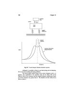
magnetic markers in the road and in-vehicle devices working cooperatively. Data
flows for both assisted and automated operations are shown in Figure 10.6.
10.1.4 User Attitudes Toward Automated Vehicle Operations
Various surveys have been conducted regarding user acceptance of, and concerns
about, automated vehicle operation. For instance, participants at Demo ’97 gave a
quite high rating to the systems shown there. In general, though, such surveys suffer
from the limitation that the respondents have not experienced such a system. Given
this caveat, some results are nevertheless interesting.
During 2000-2001, the U.K. Highways Agency funded a study to assess user
acceptance of AHS, including people’s reasons for or against such a system [5].
Three basic stages were presented to survey participants: enhanced driver informa
-
tion, driver assistance with partial vehicle control, and fully automated control. A
total of 646 interviews were performed, of which 20% were with either heavy truck
or motorcoach drivers.
Not surprisingly, two clear groups emerged: those who accept relinquishing
control to the vehicle and those who do not. This type of opposition is a philosophi
-
cal stance that will not be addressed with information, only through experience with
proven systems.
Fifty-four percent of the participatants could envision such a system, 22% were
a “maybe,” and 24% did not see it happening. If such a system did come into being,
60% said they would use it, 24% were a “maybe,” and 15% responded negatively.
The respondents who accepted the concept of a fully automated highway saw
the benefits as reduced road congestion, uniform speed, and greater certainty and
predictability of trip times. Within the total group, four main concerns were voiced
regarding AHS: system reliability, surrendering control, cost to the government (i.e.,
impact on their taxes), and the personal cost of purchasing a system.
232 Fully Automated Vehicles
RVC
Vehicle
Roadside information data bus (optical fiber or wireless)
Driver
In-vehicle data bus
Near obstacle and surface condition
Hidden obstacles on curves or intersections
Road geometry (curve, slope, merge, etc)
Surface condition ( water, snow, ice, etc)
Weather condition (rain, fog, snow, wind, etc)
Traffic flow condition (volume, speed, congest, etc )
Information sensor
Information processor Information provision
Information acquisition
(OBU, GPS, IVC)
Decision making
Actuator
Detection (Recognition)
Judgment
Operation
Automated
Assistant
Loops, cameras, radar, weigh-in-motion, DGPS
Beacon, LCX, broadcast
Lane marker (magnetic) Sign board
Figure 10.6 Data flows for China’s IHS. (Source: National Center of ITS Engineering &
Technology, China.)
10.2 Truck Automation
10.2.1 Electronic Tow-Bar Operations and Driver Assistance
CHAUFFEUR Project [6–8]
The European CHAUFFEUR project focused on the
development of “electronic tow-bar” technology (i.e., the ability of heavy trucks to
follow one another in automated platooning mode). CHAUFFEUR, initiated in the
mid nineties and completed in 2003, was led by DaimlerChrysler, with IVECO,
CRF, and Renault as major partners.
Benefits for electronic tow-bar operations explored in the program included the
following:
•
Reduced fuel consumption (up to 20%);
•
Reduced environmental impact;
•
Improvement of traffic flow;
•
More comfortable working conditions;
•
Increased safety.
There is additionally the potential for significant savings in labor costs in the far
future, with trucks actually operating in an unmanned follower mode for regular
commercial service.
The electronic tow-bar system relies on intervehicle communication (5.8-Ghz)
and the detection of a pattern of infrared markers on the back of truck trailers, in
addition to standard radar and vision sensing. In this application, only the leading
vehicle is driven by a human driver, and the “towed” vehicles are completely oper-
ated by a vehicle controller to follow the leader at a very close distance.
CHAUFFEUR2 demonstrated a three-truck platoon operating at highway
speeds, with spacings of approximately 10m. Platoon coupling and decoupling,
lane changes, acceleration from stop, and braking to a stop were among the maneu
-
vers demonstrated. Significantly, DaimlerChrysler implemented this capability on a
fully drive-by-wire (i.e., electronically actuated) vehicle. The design was tested in
simulation for up to 10 trucks in the platoon.
10.2 Truck Automation 233
Figure 10.7 CHAUFFEUR trucks in platoon mode. (Source: DaimlerChrysler AG.)
The platoon distance controller used inputs from IR image processing, onboard
sensors, and sensor data from the lead vehicle and the immediately preceding vehi
-
cle. The lateral platoon controller used only the inputs of the IR image processing as
the IR pattern was detected on the preceding vehicle. In this sense, the tow-bar func
-
tionality acted as a vehicle follower, as opposed to a road follower. In Figure 10.7,
the circular IR pattern used for tracking can be seen on the rear of the lead truck.
Based on user needs studies, CHAUFFEUR2 also defined a Chauffeur Assis
-
tant function, in which the truck is able to follow any other vehicle at safe
following distances. Chauffeur Assistant functions can be described as a combi
-
nation of vision-based lane-keeping and enhanced ACC at short, but still safe,
intervehicle gaps.
Brake performance monitoring was implemented in the Chauffeur Assistant to
estimate available road friction. An algorithm based on wheel slip and engine torque
provided real-time friction monitoring. Overall braking performance also took into
account variations in stopping distances based on vehicle payload.
The CHAUFFEUR2 team examined a wide range of additional issues, including
the following:
•
Human machine interface;
•
System evaluation;
•
Safety concepts;
•
Traffic simulations;
•
Concepts for freight logistics;
•
Cost/benefit analyses for the systems;
•
User/customer acceptance;
•
Legal and liability implications.
For example, Chauffeur Assistant vehicles were shown in traffic simulations to
have up to a 2.5% improvement in lane capacity, and electronic tow-bar platoons
were shown to be most viable in low traffic situations, given their tendency to
impede lane changes for surrounding vehicles in more dense traffic.
While still some ways from entering the commercial market, the CHAUFFEUR
project achieved a new level of capability in truck automation. The Chauffeur Assis
-
tant can be seen as relatively near-term, as truckers adopt mature ACC technology
and marry that with new products in LKA. Implementation of truck platoons, how
-
ever, is expected to take quite some time—many experts believe that this type of
trucking operation would only be allowed on dedicated truckways, which have not
yet been constructed (see next section).
California PATH Experimentation with Truck Platoons California PATH has been
another focal point for truck automation technology. Here, researchers equipped three
Freightliner tractors with full automation capability, including platooning. Evaluations
were conducted to assess fuel consumption and emissions improvements with various
platoon spacings.
An extensive technology suite was integrated onto the vehicles, including sen
-
sors, actuators, and communications systems as shown in Figure 10.8.
234 Fully Automated Vehicles
Improvements in fuel consumption on the order of 20% were measured due to
platooning operations. For emissions, CO2 reductions over 17% were noted for fol-
lower trucks at 4-m spacings. For NOx, the lead truck gained the greater advantage,
with reductions of over 4% at 4-m spacings.
10.2.2 Truck Automation for Long-Haul Application: Deployment Studies
In France, LIVIC is leading research regarding truck automation issues [9]. Interest
is motivated by the freight movement situation there, in which trucks carry 80% of
the goods, a figure that is increasing by 3.2% annually. Also, given France’s loca
-
tion as a European crossroads, long-distance freight flows (150 km or more) com
-
prise 75% of the ton kilometers. With 50% of truck travel on motorways, the
potential of truck automation to address future demand (and lessen the burden on
existing traffic) is high.
LIVIC has conducted a detailed assessment of truck automation deployment,
including the following:
•
Modeling and assessment at the vehicle level;
•
Regulation;
•
Nature and segmentation of freight transport;
•
Business issues for freight carriers (including driver issues);
•
Candidate deployment paths for progressive implementation;
•
Assessment of candidate deployment paths.
Three scenarios were examined:
10.2 Truck Automation 235
Automated heavy truck components
Cummins
C-Celect
engine ECU
+
Vehicle-to-vehicle
communication
system
WABCO "Euro" EBS
Accelerometer
and gyroscope
Magnetometer sensor array bar
PC104 control
computer
Lidar and radar sensors
Steering actuator
Figure 10.8 Technology suite on PATH automated truck. (Courtesy of California PATH.)
•
Automated trucks operating in mixed traffic on existing motorways;
•
Building new dedicated lanes for automated trucks along the existing motor
-
ways;
•
Building new dedicated motorways for automated truck operations on new
road alignments.
The first two options were rejected as impractical due to cost and space con
-
straints, as well as a desire to avoid mixing automated trucks in or near regular traffic.
The last option—building new motorways exclusively for automated trucks—was seen
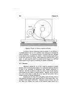
as worthy of further study. A 1,000-km motorway between Calais and Bayonne was
defined (Figure 10.9), with one lane per direction plus an emergency lane. As an
express highway, there would only be eight interchanges along this route, connecting
to existing freeways.
Within this exclusive motorway concept, three scenarios were designed and con
-
sidered as acceptable:
1. CHAUFFEUR-type operation with the formation of platoons outside the
motorway (convoy statically constituted);
236 Fully Automated Vehicles
Saint-Nazaire
Brest
Quimper
Lorient
Nantes
La Rochelle
Bordeaux
Niort
Pau
Perpignan
Beziers
Toulouse
Montauban
Limoges
Poitiers
Cholet
Angers
Rennes
Saint-Malo
Caen
Tours
Le Mans
Evreux
Paris
Beauvais
Amiens
Saint-Quentin
Lille
Dunkerque
Reims
Metz
Nancy
Strasbourg
Colmar
Mulhouse
Besancon
Chalon Surisaone
Annecy
Lyon
Chambery
Grenoble
Valence
Avignon
Arles
Aix-En-Provence
Marseille
Nice
Calais
Le Havre
Orleans
Bourges
Troyes
Dijon
Figure 10.9 Proposed North-South automated truckway in France (shown as heavy bold line).
(Source: LIVIC.)
2. CHAUFFEUR-type operation with platoons dynamically constituted on the
motorway itself (convoy dynamically constituted);
3. Separate automated trucks (automated highways), with no interaction or
coordination between trucks.
The researchers performed evaluations of traffic flow performance traded off
against safety. The platooning simulation included the following parameters:
•
Speed: 110 km/h;
•
Interdistance between trucks in a platoon: 15m;
•
Minimal interdistance between platoons: 45m;
•
Homogeneous emergency braking inside a platoon;
•
Reaction time for emergency braking: 0.4s;
•
Four trucks per platoon.
Simulations were conducted for both a defined safety level 1 (no collision with
hard braking by a vehicle ahead) and a more stringent safety level 2 (only minimal
collisions in “brick wall ahead” case). These were compared against a base case of
1,000 trucks an hour, at 90 km/hr, for manual driving in such a facility, with the
driver capable of safety level 1.
Platooning capacity for level 1 was shown to increase to 2,600 trucks per hour,
with 1,800 trucks per hour for level 2. For the free agent automated truck scenario
number three above, level 1 allowed 3,100 trucks per hour, with 1,800 trucks per
hour for level 2. Therefore, a two- to three-fold increase in capacity is possible with
truck automation, based on the simulations. Or in other words, a one-lane auto-
mated truckway could fulfill the same function as a two- or three-lane regular road.
Given the safety constraints in the simulation, platoons did not show an advantage
in lane capacity over the free-agent mode; however, platooning offers significant
savings in fuel and reduced emissions.
What Would It Cost? Highways are notoriously costly, and the French truckway would
be no exception. Total cost was estimated at over 6 billion euro, but at an average of 6
million euro per kilometer, these costs are in line with normal highway construction
costs.
Driver reactions were also assessed. Their prime values emerged as
freedom, autonomy, and responsibility for the vehicle. They felt positive about
the higher speeds possible with automation, as well as the option of sleeping
while in automated mode if the systems were truly safe. Safety of the systems
was a recurrent theme, as well as a desire to be able to take over control of the
vehicle if they felt it necessary. The platoon concept was not well received, as it
would require them to rely on the actions of other drivers if within the platoon,
or pose too heavy a responsibility if they were the lead driver.
Why Not Put All This Freight on Rail? The full discussion is a complex one, but
suffice it to say that some types of freight make most sense for rail, and other freight
lends itself to trucks. In almost all cases, freight must get to its final destination by
truck even if part of its journey is by rail. Therefore, a key factor in the truck/rail
choice is the time and labor costs of load transfers between rail cars and trucks.
10.2 Truck Automation 237
10.2.3 Automation in Short-Haul Drayage Operations [10]
The use of automated freight vehicles in Chicago for intermodal freight interchange
was studied by California PATH and local partners under the cooperative vehi
-
cle-highway automation system (CVHAS) program. Chicago is a hub for freight
movement in the United States because it is the meeting place of eastern and western
U.S. railroad lines, as well as two Canadian railroads. Significant drayage truck traf
-
fic occurs between the rail-heads for the eastern and western railroad lines—the rail
-
road gauges are incompatible, therefore freight must be off-loaded, trucked to the
other line, and reloaded for freight passing through the region. Obviously, this cre
-
ates a significant burden on the local road network.
In 1981, the physical feasibility of constructing truck-only lanes on available rail
right-of-way to connect up to 12 of the major intermodal yards had been estab
-
lished. The PATH study examined the added benefit of automated truck operations
on these lanes. Changes in freight flows since 1981 resulted in a modified plan; the
researchers defined both a 44-mile short-term and an extended long-term alignment
to serve rail yards, industrial parks, and regional points-of-entry.
Modeling was applied to represent issues such as the following:
•
Vehicle travel times and container loading/unloading times;
•
Distribution of container travel times to connect between terminals;
•
Container capacity per lane of automated roadway;
•
Interactions between automated freight operations and cross traffic;
•
Capital and operating costs;
•
Emissions and fuel consumption.
Based on traffic and other analyses, the following operational concept alterna-
tives were chosen for further analysis:
•
Alternative 1: Baseline concept (no CVHAS technologies, no truck-only
facilities);
•
Alternative 2: Truck facility without CVHAS technologies, open to all trucks,
originally consisting of one standard 12-foot lane in each direction and a sec
-
ond lane added on key segments by 2015;
•
Alternative 3: Narrow-lane truck facility exclusively for equipped trucks, with
CVHAS-automated steering technology;
•
Alternative 4: Narrow-lane truck facility exclusively for equipped trucks, with
fully automated CVHAS technologies (automatic steering, automatic speed
and spacing control with two or three truck platoons if warranted);
•
Alternative 5: Time-staged automation:
•
Truck facility without CVHAS technologies before 2015;
•
In 2015, upgrading the facility to be an automated truck-way (automatic steer
-
ing, speed and spacing control with two or three truck platoons);
•
One standard 12-foot lane in each direction to support manual driving in first
phase.
238 Fully Automated Vehicles
In each of these cases, the truck lanes are accompanied by a shoulder lane to
provide space to store any failed vehicles, thereby ensuring that a single failed truck
does not block the entire facility.
For the cost-benefit analysis, several factors were considered:
•
Travel time savings;
•
Costs for equipping trucks;
•
Automatic longitudinal control only versus full automation, adjusted for
higher costs in the near term and lower costs in the long term, as related prod
-
ucts proliferate in the trucking industry;
•
Predicted annual growth rates in traffic demand;
•
Narrower lanes for automated trucking;
•
Reductions in fuel consumption (due to reduced aerodynamic drag based on
platooning);
•
Construction costs (between $1.5 million and $6.5 million per mile depending
on local features);
•
Right-of-way acquisition costs;
•
Annual operations and maintenance costs;
•
Option of charging tolls for conventional truck lane.
The cost-benefit analysis period was 20 years, from 2005 to 2025. Cost/benefits
as compared to the “do nothing” baseline are shown in Table 10.2.
All new truck lane alternatives were determined to be cost-effective compared
to the base case. Alternative 5 is particularly attractive since deployment of CVHAS
systems occurs later, when vehicle costs are lower and traffic volumes higher.
One promising scenario of interest to the researchers, which may be examined
in a future study, is the alternative of automated truck platoons with no drivers in
following vehicles.
10.2.4 Insertion of Automated Truck Lanes in Urban Areas [11]
Various studies have been performed in southern California to examine how
truck-only lanes could be inserted into that dense urban area to accommodate heavy
freight flows, such as the numerous trucks traveling from the seaports to rail centers
inland. For instance, creation of truck-only lanes on 61 km of highway SR-60 was
studied and found to require extensive construction for two lanes per direction,
including elevated roadways, with a cost estimate of $4.3 billion. However, by
10.2 Truck Automation 239
Table 10.2 Cost/Benefit Ratios for Truck Automation Options in CVHAS Chicago Study
Alternative Cost/benefit compared
to the “do nothing” case
Alternative 2 (truck lanes with no
CVHAS)
3.78
Alternative 3 (automatic steering) 3.46
Alternative 4 (fully automated) 2.61
Alternative 5 (time staged automation) 5.32
operating three-truck automated platoons, the same capacity could be achieved with
a single lane each direction and no need for elevated lanes, at a cost of $1.37 billion,
a massive cost savings.
Other discussions are under way in the San Diego area to allow driver-assisted
or automated trucks to use the carpool lanes in off-peak hours, as a way of creating
truck-only facilities to optimize freight flows.
For truckers to use such a system, they would obviously have to invest in auto
-
mation equipment. The premise is that their operational efficiency would increase
sufficiently to justify the cost.
10.3 Automated Public Transport
It is not uncommon to find forms of automated public transport in major cities, typi
-
cally serving airports or subways. These rail-based approaches make sense in such
cases and comprise a relatively low risk environment for the technology, as move
-
ment occurs in essentially one dimension. Automated rubber-tired public transport
began public service in 1997 and various forms have been implemented since. The
approach has been to minimize the complexity of the situation, either by maintain-
ing low-speed or operating the vehicles in restricted environments.
Automated rubber-tired transport is infinitely more flexible, since roads are
everywhere and rails are not. Further, unmanned versions allow for reduced labor
costs.
In addition to automation of the basic vehicle movements, one special applica-
tion in this arena is precision docking. Precision docking refers to the ability of a bus
to stop at a precisely defined spot, both laterally and longitudinally, at the passen-
ger-loading platform. This allows for better platform design and much faster pas-
senger loading and unloading, which is an important operational benefit. Because
vehicle-platform gaps of only a few centimeters can be achieved, persons using
wheelchairs and strollers also benefit.
Here we review some of the key operational systems as well as ongoing research.
10.3.1 ParkShuttle [12]
In this arena, FROG Navigation Systems was first to market with an operational
system. Its ParkShuttle was implemented in 1997 to serve passenger transport
between remote parking and the terminal at Amsterdam’s Schipol Airport (see Fig
-
ure 10.10). Since then, another system has begun service at an office park in Rotter
-
dam. The technology is even the basis for a fascinating “teacup” ride at Disneyland
Tokyo.
FROG was originally proven in indoor factory applications. Each vehicle has an
onboard computer that stores an electronic map of the operational area. Using this
map, the vehicle is able to plan its route, based on a known starting position. Wheel
revolutions are measured to monitor distance traveled, and passive RF transponders
are embedded in the pavement as calibration points. This technique allows for posi
-
tioning accuracy of less than 3 cm. Ultrasonic sensors around the vehicle’s perimeter
detect any obstacles, causing the vehicle to stop. The ParkShuttle is unmanned and
passengers operate it in the fashion of a “horizontal elevator” to select destinations.
240 Fully Automated Vehicles
10.3.2 Intelligent Multimode Transit System (IMTS) [13]
The IMTS, developed by Toyota, was first implemented as a parking shuttle for the
Awaji Island Theme Park in Japan. Based on its success there, the system will truly
have its “coming out party” as a key link in transporting visitors within Expo 2005
in Nagoya. The vehicle design for Expo 2005 is shown in Figure 10.11.
IMTS is a driverless transit system that allows automated platoon operation on
dedicated roads, as well as manual human operation on normal roads. The system is
thoroughly fail-safe, based on automatic speed regulation, intervehicle communica-
tions, ground communications, and other means. In fact, due to its rail-like nature,
it was necessary for IMTS to comply with stringent Japanese rail standards, which it
has done successfully.
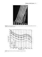
The IMTS vehicles are guided by magnetic markers in the roadway, which also
provide positioning information. The steering control subsystem is shown in Figure
10.12, with the response pattern of the magnetic sensor shown as Figure 10.13. Up
10.3 Automated Public Transport 241
Figure 10.10 ParkShuttle operating at Schipol Airport, Amsterdam. (Courtesy www.2getthere.nl.)
Figure 10.11 An artist’s rendering of IMTS in platoon operation at EXPO 2005 Aichi, Japan.
(Source: Toyota.)