Machine Design Databook Episode 3 part 2 ppsx
Bạn đang xem bản rút gọn của tài liệu. Xem và tải ngay bản đầy đủ của tài liệu tại đây (384.23 KB, 40 trang )
The difference in temperature (ÁT) of the bearing
and of the cooling medium can be found from the
equation
The difference between the bearing-wall temperature
t
b
and the ambient temperature t
a
, for three main
types of lubrication by oil bath, by an oil ring, and
by waste pack or drop feed
BEARING CAP
The bearing cap thickness
H
d
¼
ðÁT þ18Þ
2
427k
ðLdÞ
Customary Metric ð23-80cÞ
where H
d
in kcal/s, ðLdÞ in m
2
, ÁT in 8C values of
k are as given inside parentheses under
Eq. (23-80a) for US customary system units
and values of k for customary metric units
also given under Eqs. (23-80a) and (23-80b)
ðÁT þ 18Þ
2
¼ K
0
Pv SI ðMetricÞð23-81Þ
where P in N/m
2
(kgf/mm
2
), v in m/s, and ÁT in K
(8C)
K
0
¼ 0.475 (4:75 Â 10
6
) for bearings of light construc-
tion located in still air
¼ 0.273 (2:7 Â10
6
) for bearings of heavy con-
struction and well ventilated
¼ 0.165 (1:65 Â10
6
) for General Electric Com-
pany’s well-ventilated bearing
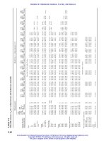
Refer to Fig. 23-46 for t
b
À t
a
’
t
0
À t
b
2
h
c
¼
ffiffiffiffiffiffiffiffiffiffi
3Wa
2L
r
ð23-82Þ
Particular Formula
0
0
1
2
3
4
10 20 30 40 50 60 70
0
1
3
5
7
9
11
13
15
17
19
21
80 90
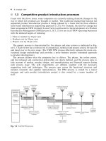
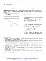
Well ventilated
Average
Thin shell not attached to
radiating mass
(a)
FIGURE 23-45 The rate of heat dissipated from a journal bearing.
(b)
Temperature rise (t
b
t
a
)
k(t
b
t
a
), ft-ibf/min/in
2
/ F
1000
900
800
700
600
500
400
300
200
100
0
020
40
60
80 100
120 140 160
3
2
1
1 - Thin shell not attached to
large radiating mass
3 - Well ventilated bearing
2 - Average industrial
bearing, unventilated
DESIGN OF BEARINGS AND TRIBOLOGY 23.55
Downloaded from Digital Engineering Library @ McGraw-Hill (www.digitalengineeringlibrary.com)
Copyright © 2004 The McGraw-Hill Companies. All rights reserved.
Any use is subject to the Terms of Use as given at the website.
DESIGN OF BEARINGS AND TRIBOLOGY
The deflection of the cap
The thickness of cap from Eq. (23-71)
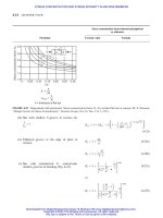
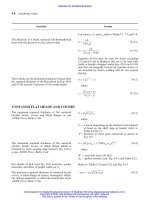
EXTERNAL PRESSURIZED BEARING OR
HYDROSTATIC BEARING: JOURNAL
BEARING (Fig. 23-47)
The pressure in the lower pool of quadrant 1
(Fig. 23-47)
y ¼
Wa
3
4ELh
3
c
ð23-83Þ
h
c
¼ 0:63a
3
ffiffiffiffiffiffiffiffiffi
W
ELy
s
ð23-84Þ
where the deflection should be limited to 0.025 mm
(0.001 in)
P
1
¼ K
1
P
o
ð23-85aÞ
where
K
1
¼
1
1 þ
4
P
o
P
0
À 1
4
þ 2:121" þ1:93"
2
À 0:589"
3
ð23-85bÞ
Particular Formula
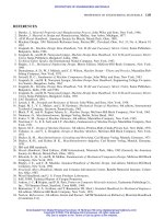
FIGURE 23-46 Relation between oil film temperature and
bearing wall temperature.
Temperature rise of wall above
ambient t
b
t
a
, C
40
0
10
20 30
70
60
50
40
30
20
10
0
Oil film temperature rise above ambient, t
o
t
a
, C
Drop
feed
Still air
Moving air
Oil
ring
Still air
Moving air
Oil
bath
Still air
Moving air
23.56 CHAPTER TWENTY-THREE
Downloaded from Digital Engineering Library @ McGraw-Hill (www.digitalengineeringlibrary.com)
Copyright © 2004 The McGraw-Hill Companies. All rights reserved.
Any use is subject to the Terms of Use as given at the website.
DESIGN OF BEARINGS AND TRIBOLOGY
The pressure in the upper pool of quadrant 3 (Fig.
23-47)
The pressure in the left pool of quadrant 2 (Fig. 23-47)
The pressure in the right pool of quadrant 4 (Fig.
23-47)
The flow of lubricant through the lower quadrant 1 of
the bearing from the manifold
P
3
¼ K
3
P
o
ð23-86aÞ
where
K
3
¼
1
1 þ
4
P
o
P
0
À 1
4
þ 2:121" þ1:93"
2
þ 0:589"
3
ð23-86bÞ
P
2
¼ K
2
P
o
ð23-87aÞ
where
K
2
¼
1
8
P
0
P
o
ð6:283 þ3:425"
2
Þð23-87bÞ
P
4
¼ K
4
P
o
ð23-88aÞ
where
K
4
¼
1
8
P
0
P
o
ð6:283 þ3:425"
2
Þð23-88bÞ
Q
1
¼
3
d
4
P
1
96l
1
C
PF1
ð23-89aÞ
where
C
PF1
¼
4
À 2:121" þ1:93"
2
À 0:589"
3
ð23-89bÞ
Particular Formula
b
w
h
e
1
(a)
(b)
(c)
3
2
Oil
inlet
Hydraulic resistance
Oil inlet hole
Oil
Constant pressure oil manifold
4
e
t
1
L
3
l
1
l
1
l
1
P
s
h
min
h
max
d
FIGURE 23-47 (a) and (b) schematic diagram of a full cylindrical hydrostatic bearing; (c) oil pressure distribution along the
bearing. [Shaw and Macks
10
]
DESIGN OF BEARINGS AND TRIBOLOGY
23.57
Downloaded from Digital Engineering Library @ McGraw-Hill (www.digitalengineeringlibrary.com)
Copyright © 2004 The McGraw-Hill Companies. All rights reserved.
Any use is subject to the Terms of Use as given at the website.
DESIGN OF BEARINGS AND TRIBOLOGY
The flow of lubricant through the left quadrant 2 of
the bearing from the manifold
The flow of lubricant through the upper quadrant 3 of
the bearing from the manifold
The flow of lubricant through the right quadrant 4 of
the bearing from the manifold
The total flow of lubricant through quadrant of the
bearing from the manifold assuming P
2
¼ P
4
¼ P
0
(good approximation)
The flow factor in Eq. (23-81b)
The external load on the hydrostatic journal bearing
The load factor
The pressure ratio connecting the dimensions of the
bearing and its external resistances
Q
2
¼
3
d
4
P
2
768l
1
C
PF2
ð23-90aÞ
where
C
PF2
¼ 6:283 þ 3:425"
2
ð23-90bÞ
Q
3
¼
3
d
4
P
3
48l
1
C
PF3
ð23-91aÞ
where
C
PF3
¼
4
þ 2:121" þ1:93"
2
þ 0:589"
3
ð23-91bÞ
Q
4
¼
3
d
4
P
4
768l
1
C
PF4
ð23-92aÞ
where
C
PF4
¼ C
PF2
¼ 6:283 þ 3:425"
2
ð23-92bÞ
Q ¼ Q
1
þ Q
2
þ Q
3
þ Q
4
ð23-93aÞ
Q ¼
3
d
4
P
o
48l
1
G ð23-93bÞ
where G ¼ flow factor given by Eq. (23-94)
G ¼ C
PF1
K
1
þ
1
8
ðC
PF2
K
2
þ C
PF4
K
4
ÞþC
PF3
K
3
¼ C
PF1
K
1
þ
1
4
C
PF2
K
2
þ C
PF3
K
3
ð23-94Þ
since K
2
¼ K
4
and C
PF2
¼ C
PF4
W ¼ðP
1
À P
3
Þ
A þ
A
0
2
¼ P
o
A þ
A
0
2
F
PFW
ð23-95Þ
where F
PFW
¼ load factor given by Eq. (23-95)
F
PFW
¼ K
1
À K
3
ð23-96Þ
P
o
P
0
¼ 1 þ 6
d
d
c
c
d
c
3
l
c
l
1
ð23-97Þ
Particular Formula
23.58 CHAPTER TWENTY-THREE
Downloaded from Digital Engineering Library @ McGraw-Hill (www.digitalengineeringlibrary.com)
Copyright © 2004 The McGraw-Hill Companies. All rights reserved.
Any use is subject to the Terms of Use as given at the website.
DESIGN OF BEARINGS AND TRIBOLOGY
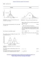
IDEALIZED SLIDER BEARING (Fig. 23-48)
Plane-slider bearing
The pressure at any point x
The load carrying capacity
The resultant shear stress at any point along the slider
(Fig. 23-48)
The shear stress at any point on the surface of the
moving member of the bearing (i.e., slider at y ¼ 0)
(Fig. 23-48)
The shear stress at any point on the surface of the
stationary member of the bearing (i.e., shoe at
y ¼ h) (Fig. 23-48)
P ¼
U
B
C
s1
ð23-98aÞ
where
C
s1
¼
6x
1
ð1 Àx
1
Þ
ð À2aÞða À þ x
1
Þ
2
ð23-98bÞ
¼
h
2
À h
1
B
; a ¼
h
2
B
; x
1
¼
x
B
ð23-98cÞ
W ¼
6UL
2
C
s2
ð23-99aÞ
where
C
s2
¼ ln
a À
a
þ
2
2a À
ð23-99bÞ
¼
U
B
C
s3
ð23-100aÞ
where
C
s3
¼
Bða À þx
1
ÞÀ2y
B
Â
3ða À þx
1
À 2ax
1
Þ
ð À2aÞða À þ x
2
Þ
3
þ
1
a À þx
1
ð23-100bÞ
m
¼
U
B
C
s4
ð23-101aÞ
where
C
s4
¼
4
a À þx
1
À
6aða ÀÞ
ð2a ÀÞða À þ x
1
Þ
2
ð23-101bÞ
s
¼
U
B
C
s5
ð23-102aÞ
where
C
s5
¼
À2
a À þx
1
À
6aða ÀÞ
ð2a ÀÞða À þ x
1
Þ
2
¼
h
2
À h
1
B
and h ¼ Bða À þx
1
Þð23-102bÞ
Particular Formula
2
1
B
x
x
z
y
h
U
F
w
L
x
FIGURE 23-48 Plane slider
bearing with an angle of
inclination.
DESIGN OF BEARINGS AND TRIBOLOGY
23.59
Downloaded from Digital Engineering Library @ McGraw-Hill (www.digitalengineeringlibrary.com)
Copyright © 2004 The McGraw-Hill Companies. All rights reserved.
Any use is subject to the Terms of Use as given at the website.
DESIGN OF BEARINGS AND TRIBOLOGY
The frictional force on the moving member of the
bearing (i.e., slider)
The frictional force on the stationary member of the
bearing (i.e., shoe)
The coefficient of friction
The distance of the pressure center from the origin of
the coordinates, i.e., from the lower end of the shoe
(Fig. 23-48)
Pivoted-shoe slider bearing (Fig. 23-48 and
Fig. 23-52)
The load-carrying capacity
The frictional force on the moving member of the
bearing (i.e., slider)
The frictional force on the stationary member of the
bearing (i.e., shoe)
F
m
¼ ULC
s6
ð23-103aÞ
where
C
s6
¼À
4
ln
a À
a
À
6
2a À
ð23-103bÞ
F
s
¼ ULC
s7
ð23-104aÞ
where
C
s7
¼
2
ln
a À
4
þ
6
2a À
ð23-104bÞ
¼
F
m
W
¼
À2ð2a ÀÞln
a À
a
À 3
2
3ð2a ÀÞln
a À
a
þ 6
ð23-105Þ
"
xx ¼
ða ÀÞð3a ÀÞ
a À
a
À 2:5
2
þ 3a
ð À2aÞln
a À
a
À 2
2
2
6
6
6
4
3
7
7
7
5
B
ð23-106Þ
W ¼
6ULB
2
h
2
2
C
PW
ð23-107aÞ
where
C
PW
¼
1
q
2
lnð1 þqÞÀ
2
qðq þ2Þ
ð23-107bÞ
Refer to Table 23-17 for C
PW
.
F
mP
¼
ULB
h
2
C
PFm
ð23-108aÞ
where
C
PFm
¼
4
q
lnð1 þqÞÀ
6
2 þq
ð23-108bÞ
Take C
PFm
from Table 23-17 for various values of q.
F
sP
¼
ULB
h
2
C
PFs
ð23-109aÞ
where
C
PFs
¼À
2
q
ln
ð1 þqÞa
2
þ
6
2 þq
ð23-109bÞ
Particular Formula
23.60 CHAPTER TWENTY-THREE
Downloaded from Digital Engineering Library @ McGraw-Hill (www.digitalengineeringlibrary.com)
Copyright © 2004 The McGraw-Hill Companies. All rights reserved.
Any use is subject to the Terms of Use as given at the website.
DESIGN OF BEARINGS AND TRIBOLOGY
The coefficient of friction
The distance of the pivoted point from the lower end
of the shoe (Fig. 23-39), i.e., the distance of the pres-
sure center from the origin of the coordinates
DESIGN OF VERTICAL, PIVOT, AND
COLLAR BEARING
Pivot bearing (Figs. 23-49, 23-50, and 23-53)
FLAT PIVOT
The total axial load on the flat pivot with extreme dia-
meters of the actual contact d
1
and d
2
The friction torque based on uniform intensity of
pressure with extreme diameters of the actual contact
d
1
and d
2
The friction torque based on uniform wear with
extreme diameters of the actual contact d
1
and d
2
The power absorbed by friction with d as the diameter
of flat pivot bearing
CONICAL PIVOT
The friction torque based on uniform intensity of
pressure with extreme diameters of the actual contact
d
1
and d
2
The friction moment which resists the rotation of the
shaft in a conical pivot bearing for uniform wear
The loss of power in vertical bearing
¼
F
mP
W
¼
h
2
B
1
6
C
PFm
C
PW
¼
h
2
B
C
P
ð23-110Þ
where C
P
¼ coefficient of friction factor
Take C
P
from Table 23-17 for various values of q.
"
xx ¼
ð1 þqÞð3 þqÞlnð1 þqÞÀqð2:5q þ3Þ
qðq þ2Þlnð1 þqÞÀ2q
2
B
ð23-111Þ
The ratios
"
xx=B are taken from Table 23-17.
W ¼ p
d
2
1
À d
2
2
4
ð23-112Þ
M
t
¼
1
3
W
d
3
1
À d
3
2
d
2
1
À d
2
2
ð23-113Þ
M
t
¼ W
d
1
þ d
2
4
ð23-114Þ
P
¼
Wdn
0
478
SI ð23-115aÞ
where P
in kW, W in N, d in m, and n
0
in rps
P
¼
Wdn
189;090
USCS ð23-115bÞ
where P
in hp, W in lbf, d in in, and n in rpm
M
t
¼
1
3
W
sin
d
3
1
À d
3
2
d
2
1
À d
2
2
ð23-116Þ
where 2 ¼ cone angle of pivot, deg
M
t
¼
W
sin
d
1
þ d
2
4
ð23-117Þ
P
¼ 6:2 Â 10
8
d
2
Ln
02
SI ð23-118aÞ
where P
in kW, in Pa s, d and L in m, and n
0
in rps
Particular Formula
w
d
Oil
Oil groove
Radial
oil groove
w
d
(a)
(b)
FIGURE 23-49 Pivot thrust
bearing
DESIGN OF BEARINGS AND TRIBOLOGY
23.61
Downloaded from Digital Engineering Library @ McGraw-Hill (www.digitalengineeringlibrary.com)
Copyright © 2004 The McGraw-Hill Companies. All rights reserved.
Any use is subject to the Terms of Use as given at the website.
DESIGN OF BEARINGS AND TRIBOLOGY
If the journal and the bearing are eccentric and the
distance between their axes is ", the power loss is
calculated from formula
P
¼ 2:35 Â 10
À4
1
d
2
Ln
2
Customary Metric ð23-118bÞ
where P
in hp
m
,
1
in cP, d and L in cm, and n in
rpm
P
¼ 2:35 Â 10
À7
1
d
2
Ln
2
Customary Metric ð23-118cÞ
where P
in hp
m
,
1
in cP, d and L in mm, and n in
rpm
P
¼ 2:35 Â 10
6
0
d
2
Ln
2
Customary Metric ð23-118dÞ
where P
in hp
m
,
0
in kgf s/m
2
, d and L in m, and n
in rpm
P
¼ 2:35 Â 10
À3
0
d
2
Ln
2
Customary Metric ð23-118eÞ
where P
in hp
m
,
0
in kgf s/m
2
, L and d in mm, and
n in rpm
P
¼
3:8
3
1
d
2
Ln
2
USCS ð23-118fÞ
where P
in hp,
1
in cP, d and L in in, and n in
rpm
P
¼
6:2 Â10
8
d
2
Ln
02
ffiffiffiffiffiffiffiffiffiffiffiffiffiffiffiffiffiffiffi
1 Àð2"Þ
2
q
SI ð23-119aÞ
where P
in kW, in Pa s, d and L in m, and n
0
in
rps
P
¼ 2:35 Â 10
À7
1
d
2
Ln
2
ffiffiffiffiffiffiffiffiffiffiffiffiffiffiffiffiffi
1 À2"Þ
2
q
Customary Metric ð23-119bÞ
where P
in hp
m
,
1
in cP, d and L in mm, and n in
rpm
P
¼ 2:3 Â 10
6
0
d
2
Ln
2
ffiffiffiffiffiffiffiffiffiffiffiffiffiffiffiffiffiffiffi
1 Àð2"Þ
2
q
Customary Metric ð23-119cÞ
where P
in hp
m
,
0
in (kgf s/m
2
), d and L in m, and
n in rpm
P
¼
3:8
10
3
1
d
2
Ln
2
ffiffiffiffiffiffiffiffiffiffiffiffiffiffiffiffiffiffiffi
1 Àð2"Þ
2
q
USCS ð23-119dÞ
where P
in hp,
1
in cP,L andd inin, and nin rpm
Particular Formula
23.62 CHAPTER TWENTY-THREE
Downloaded from Digital Engineering Library @ McGraw-Hill (www.digitalengineeringlibrary.com)
Copyright © 2004 The McGraw-Hill Companies. All rights reserved.
Any use is subject to the Terms of Use as given at the website.
DESIGN OF BEARINGS AND TRIBOLOGY
Collar bearing (Fig. 23-51)
The average intensity of pressure with i collars
The friction moment for each collar for uniform
intensity of pressure
The total friction moment for i collars for uniform
intensity of pressure
The friction moment for each collar for uniform rate
of wear
The total friction moment for i collars for uniform
rate of wear
The friction power in collar bearing
The coefficient of friction for collar bearing
Allowable pressure P may be taken so that Pv value
for v ranging from 0.20 to 1 m/s (50 to 200 ft/min)
P ¼
W
0:784ðd
2
1
À d
2
2
Þi
ð23-120Þ
M
te
¼
1
3
W
i
d
3
1
À d
3
2
d
2
1
À d
2
2
ð23-121Þ
M
t
¼
1
3
W
d
3
1
À d
3
2
d
2
1
À d
2
2
ð23-122Þ
M
te
¼
W
i
d
1
þ d
2
4
ð23-123Þ
M
t
¼ W
d
1
þ d
2
4
ð23-124Þ
P
¼
Wðd
1
þ d
2
Þn
0
2;292;296
SI ð23-125aÞ
where P
in kW, W in N, d in m, and n
0
in rps
P
¼
Wðd
1
þ d
2
Þn
252;120
USCSU ð23-125bÞ
where P
in hp, W in lbf, d in in, and n
0
in rpm
¼ 83:8
v
0:5
p
0:67
SI ð23-126aÞ
where v in m/s and P in N/m
2
¼ 0:016
v
0:5
p
0:67
USCS ð23-126bÞ
where v in ft/min and P in psi
¼ 1:73 Â10
À3
v
0:5
p
0:67
Customary Metric ð23-126cÞ
where v in m/s and P in kgf/mm
2
Pv 707;505 SI ð23-127aÞ
where P in Pa and v in m/s
Pv 0:0715 Customary Metric ð23-127bÞ
where P in kgf/mm
2
and v in m/s
Pv 20;000 USCS ð23-127cÞ
where P in psi and v in ft/min
Particular Formula
d
Oil in
Oil in
w
FIGURE 23-50a Collar thrust
bearing.
d
2
d
1
w
The coefficient of friction for collar bearing
FIGURE 23-50b Plain
thrust bearing.
DESIGN OF BEARINGS AND TRIBOLOGY 23.63
Downloaded from Digital Engineering Library @ McGraw-Hill (www.digitalengineeringlibrary.com)
Copyright © 2004 The McGraw-Hill Companies. All rights reserved.
Any use is subject to the Terms of Use as given at the website.
DESIGN OF BEARINGS AND TRIBOLOGY
PLAIN THRUST BEARING (Fig. 23-50b)
Recommended maximum load
Approximate power loss in bearing
Lubrication flow rate to limit lubricant temperature
rise to 208C
Thrust bearing
Parallel-surface thrust bearing (Figs. 23-51 to 23-52)
The pressure at any point along the bearing
W ¼ K
1
ðd
2
1
À d
2
2
Þ SI ðUSCSÞð23-128Þ
where K
1
¼ 0:3 ð48Þ, W in N (lbf), d
1
and d
2
in mm
(in)
P
¼ K
2
d
1
þ d
2
2
n
0
W SI ðUSCSUÞð23-129Þ
where K
2
¼ 70 Â 10
À6
¼ð11 Â10
À6
Þ
P
in W (hp), n
0
in rps, and W in N (lbf)
Q ¼ K
3
P
SI ðUSCSUÞð23-130Þ
where K
3
¼ 0:03 Â 10
À6
(0.3), Q in m
3
/s (q.p.m),
and P
in W s (hp)
Refer to Table 23-8 for P and Table 23-6 for Pv
values.
P ¼
6UB
h
2
K
LP1
ð23-131aÞ
where
K
LP1
¼
x
1
À ln½ð
0
À 1Þx
1
þ 1Þ
ln
0
0
¼
2
1
; x
1
¼
x
B
ð23-131bÞ
Particular Formula
x
y
d
w
z
r
x
ω
ωr
ω
(a)
(b)
1
2
B
x
h
w
y
z
U
FIGURE 23-51 Parallel-surface thrust bearing.
23.64 CHAPTER TWENTY-THREE
Downloaded from Digital Engineering Library @ McGraw-Hill (www.digitalengineeringlibrary.com)
Copyright © 2004 The McGraw-Hill Companies. All rights reserved.
Any use is subject to the Terms of Use as given at the website.
DESIGN OF BEARINGS AND TRIBOLOGY
The ratio of the density of the lubricant leaving the
bearing to the density of the lubricant entering the
bearing
The unit load supported by a parallel-surface thrust
bearing
The approximate formula for unit load supported by
a parallel-surface thrust bearing
The pressure distribution along a tilting-pad bearing
of infinite width (Figs. 23-48 and 23-52)
0
¼
2
1
¼ 1 þ
a
1
ðt
2
À t
1
Þð23-132Þ
where a ¼ constant, a=
1
¼À0:0004, and t
1
and t
2
are the temperatures in 8C corresponding to
densities
1
and
2
, respectively
P
u
¼
6UB
h
2
K
LP2
ð23-133aÞ
where
K
LP2
¼
1
2
þ
0
1 À
þ
1
ln
0
ð23-133bÞ
P
u
¼
6UB
h
2
K
LP3
ð23-134aÞ
where K
LP3
¼ 0:09ð1 À
0
Þð23-134bÞ
Refer to Table 23-18 for K
LP3
.
P ¼
6UB
h
2
1
K
pt
ð23-135aÞ
where
K
pt
¼
ðm À1Þð1 À x
1
Þx
1
ðm þ1Þðm Àmx
1
þ x
1
Þ
2
ð23-135bÞ
m ¼ h
1
=h
2
; x
1
¼ x=B
Particular Formula
h
h
2
z
y
h
1
x
0 0.2 0.4
Ratio of
0.6 0.8 1.0
Tilting pad bearing
x
B
Pivot
c
ρ
2
ρ
1
= 0.92
0.96
0.98
0.04
0.02
h
2
6ηUB
h
2
6ηUB
2
FIGURE 23-52 Comparison of pressure distribution across tilting-pad
and parallel-surface thrust bearing.
DESIGN OF BEARINGS AND TRIBOLOGY
23.65
Downloaded from Digital Engineering Library @ McGraw-Hill (www.digitalengineeringlibrary.com)
Copyright © 2004 The McGraw-Hill Companies. All rights reserved.
Any use is subject to the Terms of Use as given at the website.
DESIGN OF BEARINGS AND TRIBOLOGY
The unit load supported by a tilting-pad bearing of
infinite width (Fig. 23-52)
OIL FILM THICKNESS
The thickness of oil film in a parallel-surface thrust
bearing
The thickness of minimum oil film at location 2 (Figs.
23-48 and 23-52)
P
u
¼
6UB
h
2
2
K
lt
ð23-136aÞ
where
K
lt
¼
1
ðm À1Þ
2
ln m À
2ðm À1Þ
m þ1
ð23-136bÞ
h ¼
ffiffiffiffiffiffiffiffiffiffiffiffiffi
6K
LP3
p
ffiffiffiffiffiffiffiffiffiffi
UB
P
s
ð23-137Þ
Refer to Table 23-18 for K
LP3
.
h
2
¼
ffiffiffiffiffiffiffiffiffi
6K
lt
p
ffiffiffiffiffiffiffiffiffiffi
UB
P
s
ð23-138Þ
Refer to Table 23-18 for K
lt
.
Particular Formula
TABLE 23-18
Comparison of load capacities of tilting-pad and parallel-surface-type of bearings
Temperature rise through bearings, 8C
0
K
LP3
K
lt
(for h
0
¼3) Relative load capacity, K
LP3
=K
lt
10 0.98 0.0018 0.025 14
38 0.96 0.0036 7
93 0.92 0.0072 3.5
Source: F. I. Radzimovsky. Lubrication of Bearings—Theoretical Principles and Designs. The Ronald Press Company. New York, 1959.
W
(a)
(b)
n
P
o
P
o
d
2
d
1
m
m’
oil supply
pressure
n’
h
FIGURE 23-53 (a) Hydrostatic step bearing; (b) plan view and general character of
pressure distribution along diameter of the bearing.
23.66 CHAPTER TWENTY-THREE
Downloaded from Digital Engineering Library @ McGraw-Hill (www.digitalengineeringlibrary.com)
Copyright © 2004 The McGraw-Hill Companies. All rights reserved.
Any use is subject to the Terms of Use as given at the website.
DESIGN OF BEARINGS AND TRIBOLOGY
For properties of lubricant bearing materials and
applications, conversion factors for viscosity, kine-
matic and Saybolt viscosity equivalents and conversion
tables for viscosity equivalent
COEFFICIENT OF FRICTION
The coefficient of friction in case of a parallel-surface
thrust bearing
Another formula for coefficient of friction in case of a
parallel-surface thrust bearing
The coefficient of friction for a tilting-pad bearing of
infinite width
HYDROSTATIC BEARING: STEP-BEARING
(Fig. 23-53)
The pressure in the pocket supplied from external
source to support the load
The load-carrying capacity
The rate of flow of lubricant through the bearing
Power loss in bearing
Refer to Tables 23-19 to 23-23.
¼
1:82
1 À
0
h
B
ð23-139Þ
¼
1
ffiffiffiffiffiffiffiffiffiffiffiffiffi
6K
LP3
p
ffiffiffiffiffiffiffiffiffi
U
P
u
B
s
ð23-140Þ
¼ K
t
ffiffiffiffiffiffiffiffiffi
U
P
u
B
s
ð23-141aÞ
where
K
t
¼
4lnm À6
m À1
m þ1
2
6lnm À12
m À1
m þ1
2
6
6
6
4
3
7
7
7
5
1=2
m ¼ h
1
=h
2
¼ film thickness ratio ð23-141bÞ
P
o
¼
8W lnðd
2
=d
1
Þ
ðd
2
2
À d
2
1
Þ
ð23-142aÞ
W ¼
P
o
ðd
2
2
À d
2
1
Þ
ln
d
2
d
1
ð23-143Þ
Q ¼
P
o
h
3
2 lnðd
2
=d
1
Þ
ð23-144Þ
P
¼ 0:062
n
02
16h
ðd
4
2
À d
4
1
Þ SI ð23-145aÞ
where P
in kW, in Pa s, h, d
1
, and d
2
in m, and n
0
in rps
P
¼ 8:3 Â 10
À4
n
0
16h
ðd
4
2
À d
4
1
Þ
Customary Metric ð23-145bÞ
where P
in hp
m
, in kgf s/mm, h, d
1
, and d
2
in
mm, and n
0
in rps
Particular Formula
DESIGN OF BEARINGS AND TRIBOLOGY
23.67
Downloaded from Digital Engineering Library @ McGraw-Hill (www.digitalengineeringlibrary.com)
Copyright © 2004 The McGraw-Hill Companies. All rights reserved.
Any use is subject to the Terms of Use as given at the website.
DESIGN OF BEARINGS AND TRIBOLOGY
TABLE 23-19
Typical properties of lubricants
Viscosity
Density, Pour Flash
Saybolt seconds, S Centipoise, cP kgf s/m
2
 10
À4
Pa s  10
À3
g/cm
3
, at point, point, Viscosity
Type and application SAE no. 15.58C 8C 8C index At 38 8CAt998CAt388CAt998CAt388CAt998CAt388CAt998C Uses
Transmission gear oil 75 0.900 À23 193 121 220 50 47 7.3 47.94 7.45 47 7.3 Combination pinion
80 0.934 À32 185 78 320 52 69 7.9 70.38 8.06 69 7.9 reduction gear units,
90 0.930 À23 232 91 1330 100 287 20.4 292.74 20.81 287 20.4 enclosed reduction gear
140 0.937 À18 260 82 3350 160 725 34 739.50 34.68 725 34 sets
250 — À15 254.5 83 5660 220 1220 47 1244.40 47.94 1220 47
Automotive oil 10W 0.870 À26 210 102 190 46 41 6.0 41.82 6.12 41 6.0 Automobile, truck and
20W 0.885 À23 227 96 330 54 71 8.5 72.42 8.67 71 8.5 marine reciprocating
30 0.891 À20 238 92 530 64 114 11.3 116.28 11.53 114 11.3 engines; very-heavy-duty
40 0.890 À18 240.5 90 800 77 173 14.8 176.46 15.10 173 14.8 oils used in diesel engines
50 0.992 À12 254.5 90 1250 97 270 19.7 275.40 20.10 270 19.7
60— ——80 — 115——————
70— — 80 — 137——————
Aircraft engine oil 0.858 À65 111 87 43 33 5 1.6 5.10 1.63 5 1.6
g
Turbojet engines
0.864 À62 146 79 59 35 10 2.5 10.20 2.55 10 2.5
0.876 À18 215.5 106 350 57 76 9.3 77.52 9.49 76 9.3
0.884 À18 224 96 514 64 111 11.3 113.22 11.53 111 11.3
g
Various reciprocating
0.887 À18 232 95 829 80 179 15.5 182.58 15.81 179 15.5 aircraft engines
0.892 À18 249 95 1240 99 268 20.1 273.36 20.50 268 20.1
0.892 À7 318 96 1711 120 369 25.0 376.38 25.50 369 25.0
Turbine-grade oil
Light 0.872 À18 210 109 150 44 32 5.4 32.64 5.51 32 5.4 Direct-connected turbines
electric motors
Medium 0.877 À12 235 105 300 53 65 8.2 66.30 8.36 65 8.2 Land-geared turbines
electric-motors
Heavy 0.885 À12 243 100 460 62 99 10.8 100.98 11.02 99 10.8 Marine-propulsion geared
turbines
Steam 0.895 14 260 101 1800 130 390 27 397.80 27.45 390 27 Railroad stationary steam
Cylinder 0.910 1.5 211 107 3750 210 810 45 826.20 45.90 810 45 engines cylindered
Oil 0.904 15.5 343 103 6470 300 1400 64 1428.00 65.28 1400 64 applications, enclosure
gears
23.68
Downloaded from Digital Engineering Library @ McGraw-Hill (www.digitalengineeringlibrary.com)
Copyright © 2004 The McGraw-Hill Companies. All rights reserved.
Any use is subject to the Terms of Use as given at the website.
DESIGN OF BEARINGS AND TRIBOLOGY
TABLE 23-19
Typical properties of lubricants (Cont.)
Viscosity
Density, Pour Flash
Saybolt seconds, S Centipoise, cP kgf s/m
2
 10
À4
Pa s  10
À3
g/cm
3
, at point, point, Viscosity
Type and application SAE no. 15.58C 8C 8C index At 38 8CAt998CAt388CAt998CAt388CAt998CAt388CAt998C Uses
Hydraulic oils Hydraulic fluids for most
Light 0.887 À42 188 64 150 42 32 4.8 32.64 4.90 32 4.8 indoor industrial
Medium 0.895 À26 207 66 310 50 67 7.3 68.34 7.45 67 7.3 hydraulic equipments
Heavy 0.901 À12 257 70 910 74 196 14.0 199.92 14.28 196 14.0 Heavier loads, higher
temperature
Extra-low-temperature 0.844 À24 110 226 74 43 14 5.2 14.28 5.30 14 5.2 Aircraft hydraulic systems
Refrigerating machine 0.895 À45.5 146 53 72 36 14 2.9 14.28 2.96 14 2.9 Ammonia compressor
oil 0.898 À37 165.5 22 195 43 42 5.1 42.84 5.20 42 5.1
0.909 À29 182 34 235 45 51 5.7 52.02 5.81 51 5.7
0.902 À23 190.5 35 335 49 72 7.0 73.44 7.14 72 7.0
Machine tools and 0.881 À4 177 80 105 39 22 3.9 22.44 3.98 22 3.9 All general-purpose
general-purpose oil 0.898 À4 199 80 205 46 44 6.0 44.88 6.12 44 6.0 lubrication, machine tools
0.915 À12 185 83 305 49 66 7.0 67.32 7.14 66 7.0
0.915 À15 199 25 510 59 110 9.9 112.20 10.10 110 9.9
0.890 À9 235 80 930 80 200 15.5 204.00 15.81 200 15.5
23.69
Downloaded from Digital Engineering Library @ McGraw-Hill (www.digitalengineeringlibrary.com)
Copyright © 2004 The McGraw-Hill Companies. All rights reserved.
Any use is subject to the Terms of Use as given at the website.
DESIGN OF BEARINGS AND TRIBOLOGY
TABLE 23-20
Journal bearing materials and applications
Dry
Ultimate tensile
strength,
su
Modules of elasticity, E
coefficient
Hardness numbers
Specific of friction, kgf/mm
2
Material Composition, % gravity kgf/mm
2
MPa Â10
4
GPa Brinell Rockwell Applications
Babbitts
Lead base Sn 10.0, Sb 15.0, 9.69 0.34 7.03 68.96 0.295 28.9 45 — Used in automobiles and electrical
Pb 75.0 equipment
Tin base Cu 8.3, Sb 8.3, 7.47 0.28 7.88 77.30 0.534 52.4 27 — Used in automotive and diesel engines,
Sn 83.4 steam turbines and motors
Cadmium base Ni 1.4, Cd 98.6 8.6 0.34 — — — — — — Used where lubrication is intermittent
Aluminum Cu 1.0, Sn 6.5 2.86 0.33 15.5 151.76 0.724 71.0 45 — Used in high-temperature high-load
alloys Ni 1.5, Al 91.0 services and in diesels; requires good
lubrication and hardened shaft
Copper alloys
Clock brass Pb 3.0, Zn 35.5, 8.4 — 38.0– 372.48– 1.055 103.5 54–142 B 40–75 Used for light load
Cu 61.5 45.0 445.45
Bronze, Sn 4.0, Pb 14.0, — 0.15 14.0 138.00 — — 45 — Used in poorly lubricated applications
high-lead Zn 1.5, Ni 1.0 with moderately heavy loads
max, Cu 79.5
Bronze, Sn 16, Pb 14.0, — 0.37 — — — — — — Same as above; can withstand higher loads
high-lead Cu 70.0
Bronze, Sn 8, Pb 3.5, 8.4 0.26 21.1 min 207.00 53 — Moderately heavy duty
lead tin Zn 3.5, Cu 85 min
Bronze, Sn 10.0, Pb 10.0, 8.86 0.15 17.58 172.46 0.773 75.8 65 — General-duty bearing bronze; load up to
80–10–10 Cu 80 min min 20.6 MPa (2.1 kgf/mm
2
); speed—4.5 m/s
Bronze, Sn 10.0, Ni 3.5, — 0.37 31.64 310.04 — — 95 — Used in medium- to heavy-duty
nickel tin Pb 2.5, Cu 84.0 application; good strength requirement
Bronze, Al 10.5, Fe 3.5, 7.6 0.52 70.30 689.74 1.125 110.4 202 — Used in heavy-duty bearings requiring
aluminum Cu 86.0 high strength and good impact resistance
Bronze, zinc Al 1.0, Si 0.8, 8.09 0.39 49.22 482.84 1.055 103.5 B 80–92 Heavy-duty impact loadings; on
Mn 2.5, Zn 37.5, min min — hardened shaft
Cn 58.2
Iron base
Gray cast C 3.5, Si 2.5, 7.2 0.37 21.10 207.00 1.898 186.2 180 — Used in refrigerators, compressors,
iron Fe 94.0 min min camshafts, high load at low speed with
good lubrication
Sintered iron Cu 7.5, Fe 92.5 — 0.30 — — — — — — Used with impregnates with oil will give
good results; load—3.4 MPa (0.35 kgf
mm
2
) and speed 0.67 m/s
23.70
Downloaded from Digital Engineering Library @ McGraw-Hill (www.digitalengineeringlibrary.com)
Copyright © 2004 The McGraw-Hill Companies. All rights reserved.
Any use is subject to the Terms of Use as given at the website.
DESIGN OF BEARINGS AND TRIBOLOGY
TABLE 23-20
Journal bearing materials and applications (Cont.)
Dry
Ultimate tensile
strength,
su
Modules of elasticity, E
coefficient
Hardness numbers
Specific of friction, kgf/mm
2
Material Composition, % gravity kgf/mm
2
MPa Â10
4
GPa Brinell Rockwell Applications
Graphite
Carbon C þ binder 1.63–1.86 0.15 0.53 5.17– — — Shore scleroscope Particularly suited to high-temperature
graphite 1.80 17.25 75 application (<4558C) where lubrication
is difficult; used in electric motors,
Carbon C þ Cu 2.9/3.8 0.17 2.11– 20.7– — — Shore scleroscope conveyors
graphite þbinder 4.22 41.4 75 Same as above, higher strength
and metal
Cemented Tungsten carbide 15.1 0.20 573.00 5621 6.885 672.5 C 80 Used in high-speed precision grinders
carbide 97.0, Co 3.0 (com- (com- (com- which require perfect alignment and
pressive) pressive) pressive) good lubrication; can withstand extreme
loading and high speeds
Wood Used in conveyors; light loads at high
speeds under 658C
Plastics and rubber
Nylon Polyamide 1.44 0.86 7.03 68.96 0.023 2.25 M 90 Used in many household appliances and
other lightly loaded applications;
requires little lubrication
Rubber 0.97–2.00 0.25–0.30 1.40– 13.73– Marine propellers, pumps, turbine, load
10.55 103.50 0.54 MPa (0.055 kgf/mm
2
)
Teflon Polytetrafluoro- 2.2 0.17 2.11 20.70 0.0042 0.410 Shore scleroscope Useful in corrosive conditions; dairy,
ethylene 50 textile, and food machinery
Textolite 2001 Phenolic, 1.36 0.18 7.03 68.96 0.0443 4.375– Used where low wear and good
graphite and 0.0647 6.35 M 100 compatibility characteristics are
cotton cloth required
TABLE 23-21
Conversion factors for viscosity
P cP kgf s/m
2
kg/m s lbf s/ft
2
lb/ft s Pa s
P 1 100 0.0102 0.1 2.0886 Â 10
À3
0.0672 0.1
cP 0.01 1 1.0297 Â 10
À4
10
À3
2.0886 Â 10
À5
6.7197 10
À3
kgf s/m
2
98.0665 9.80665 Â 10
À3
1 9.80665 0.20482 6.5898 9.80665
kg/m s 10 10
À3
0.102 1 2.0886 Â 10
À2
0.6720
lbf s/ft
2
4.788 Â 10
2
4.788 Â 10
4
4.8824 47.88 1 32.174
lb/ft s 14.882 1.4882 Â 10
3
0.1518 1.4882 0.0311 1
Pa s 10 10
3
0.102 1
23.71
Downloaded from Digital Engineering Library @ McGraw-Hill (www.digitalengineeringlibrary.com)
Copyright © 2004 The McGraw-Hill Companies. All rights reserved.
Any use is subject to the Terms of Use as given at the website.
DESIGN OF BEARINGS AND TRIBOLOGY
TABLE 23-22
Kinematic and Saybolt viscosity equivalents
Kinematic viscosity,
Metric units Saybolt viscosity, S
a
SI units
cSt cm
2
=s Â10
À2
m
2
/s Â10
À6
At 388CAt998C
2 2 2 32.6 32.9
3 3 3 36.0 36.3
4 4 4 39.1 39.4
5 5 5 42.4 42.7
6 6 6 45.6 45.9
7 7 7 48.8 49.1
8 8 8 52.1 52.5
9 9 9 55.5 55.9
10 10 10 58.9 59.3
11 11 11 62.4 62.9
12 12 12 66.0 66.5
13 13 13 69.8 70.3
14 14 14 73.6 74.1
15 15 15 77.4 77.9
16 16 16 81.3 81.3
17 17 17 85.3 85.9
18 18 18 89.4 90.1
19 19 19 93.6 94.2
20 20 20 97.8 98.5
21 21 21 102.0 102.8
23 23 23 110.7 111.4
25 25 25 119.3 120.1
27 27 27 128.1 129.0
29 29 29 136.9 137.9
30 30 30 141.3 142.3
31 31 31 145.7 146.8
33 33 33 154.7 155.8
35 35 35 163.7 164.9
37 37 37 172.7 173.9
39 39 39 181.8 183.0
40 40 40 186.3 187.6
41 41 41 190.8 192.1
43 43 43 199.8 201.2
45 45 45 209.1 210.5
47 47 47 218.2 219.8
49 49 49 227.5 229.1
50 50 50 232.1 233.8
55 55 55 255.2 257.0
60 60 60 278.3 280.2
65 65 65 301.4 303.5
70 70 70 324.4 326.7
>70 S ¼ cSt Â4:635 S ¼ cSt Â4:667
a
S ¼ cSt  4:635 at 388C; S ¼ cSt  4:667 at 998C
23.72 CHAPTER TWENTY-THREE
Downloaded from Digital Engineering Library @ McGraw-Hill (www.digitalengineeringlibrary.com)
Copyright © 2004 The McGraw-Hill Companies. All rights reserved.
Any use is subject to the Terms of Use as given at the website.
DESIGN OF BEARINGS AND TRIBOLOGY
TABLE 23-23
Conversion table for viscosity equivalents
Kinematic viscosity,
Metric units Viscosity
SI units
cSt cm
2
=s Â10
À2
m
2
/s Â10
À6
Saybolt, S Engler 8 Redwood no. 1
2.0 2.0 2.0 32.60 1.12 30.8
2.2 2.2 2.2 33.40 1.14 31.3
2.4 2.4 2.4 34.10 1.16 31.8
2.6 2.6 2.6 34.80 1.18 32.3
2.8 2.8 2.8 35.40 1.20 32.8
3.0 3.0 3.0 36.00 1.22 33.3
3.2 3.2 3.2 36.70 1.23 33.8
3.4 3.4 3.4 37.30 1.25 34.3
3.6 3.6 3.6 37.90 1.27 34.8
3.8 3.8 3.8 38.50 1.29 35.3
4.0 4.0 4.0 39.1 1.31 35.8
4.5 4.5 4.5 40.8 1.35 37.0
5.0 5.0 5.0 42.4 1.40 38.3
5.5 5.5 5.5 44.0 1.44 39.6
6.0 6.0 6.0 45.6 1.48 40.9
6.5 6.5 6.5 47.2 1.52 42.3
7.0 7.0 7.0 48.8 1.56 43.6
7.5 7.5 7.5 50.4 1.60 44.9
8.0 8.0 8.0 52.1 1.65 46.3
8.5 8.5 8.5 53.8 1.70 47.7
9.0 9.0 9.0 55.5 1.75 49.0
9.5 9.5 9.5 57.2 1.79 50.5
10 10 10 58.9 1.84 51.9
11 11 11 62.4 1.94 54.9
12 12 12 66.0 2.02 58.0
13 13 13 69.7 2.12 61.2
14 14 14 73.5 2.22 64.5
15 15 15 77.3 2.32 67.9
16 16 16 81.2 2.43 71.3
17 17 17 85.2 2.54 74.8
18 18 18 89.3 2.64 78.4
19 19 19 93.4 2.75 82.0
20 20 20 97.6 2.87 85.7
22 22 21 106.1 3.10 93.2
24 24 24 114.7 3.33 100.8
26 26 26 123.4 3.57 108.5
28 28 28 132.3 3.82 116.3
30 30 30 141.1 4.07 124.2
32 32 32 149.9 4.32 132.1
34 34 34 158.9 4.57 140.0
36 36 36 167.9 4.82 147.9
38 38 38 176.9 5.08 155.9
DESIGN OF BEARINGS AND TRIBOLOGY 23.73
Downloaded from Digital Engineering Library @ McGraw-Hill (www.digitalengineeringlibrary.com)
Copyright © 2004 The McGraw-Hill Companies. All rights reserved.
Any use is subject to the Terms of Use as given at the website.
DESIGN OF BEARINGS AND TRIBOLOGY
TABLE 23-23
Conversion table for viscosity equivalents (Cont.)
Kinematic viscosity,
Metric units Viscosity
SI units
cSt cm
2
=s Â10
À2
m
2
/s Â10
À6
Saybolt, S Engler 8 Redwood no. 1
40 40 40 186.0 5.33 164.0
42 42 42 195.0 5.59 172.0
44 44 44 204.0 5.84 180.0
46 46 46 213.0 6.10 188.0
48 48 48 222.0 6.36 196.0
50 50 50 232.0 6.62 204.0
55 55 55 255.0 7.26 225.0
60 60 60 278.0 7.90 245.0
65 65 65 301.0 8.55 265.0
70 70 70 324.0 9.21 286.0
75 75 75 347.0 9.87 306.0
80 80 80 370.0 10.53 326.0
85 85 85 393.0 11.19 346.0
90 90 90 416.0 11.85 367.0
95 95 95 439.0 12.51 387.0
100 100 100 463.0 13.16 407.0
110 110 110 509.0 14.47 448.0
120 120 120 555.0 15.80 489.0
130 130 130 602.0 17.11 529.0
140 140 140 648.0 18.43 570.0
150 150 150 694.4 19.75 611.0
160 160 160 740.0 21.05 651.0
170 170 170 787.0 22.38 692.0
180 180 180 833.0 23.70 733.0
190 190 190 879.0 25.00 774.0
200 200 200 926.0 26.32 815.0
220 220 220 1018.0 28.95 896.0
240 240 240 1111.0 31.60 978.0
260 260 260 1203.0 34.25 1059.0
280 280 280 1296.0 36.85 1140.0
300 300 300 1388.0 39.50 1222.0
320 320 320 1480.0 42.12 1303.0
340 340 340 1574.0 44.75 1385.0
360 360 360 1666.0 47.40 1465.0
380 380 380 1759.0 50.00 1546.0
400 400 400 1851.0 52.65 1628.0
500 500 500 2314.0 65.80 2036.0
600 600 600 2777.0 79.00 2443.0
700 700 700 3239.0 92.20 2850.0
800 800 800 3702.0 105.30 3258.0
900 900 900 4165.0 118.50 3668.0
1000 1000 1000 4628.0 131.60 4074.0
23.74 CHAPTER TWENTY-THREE
Downloaded from Digital Engineering Library @ McGraw-Hill (www.digitalengineeringlibrary.com)
Copyright © 2004 The McGraw-Hill Companies. All rights reserved.
Any use is subject to the Terms of Use as given at the website.
DESIGN OF BEARINGS AND TRIBOLOGY
SPHERICAL BEARINGS (Fig. 23-54)
Equivalent bearing pressure (Fig. 23-54)
Maximum bearing pressure if an average bearing life
of 10
5
number of oscillations is to be expected
Bearing life (Fig. 23-54)
B
B
Bearing
type
φ
φ
D
D
W
r
W
max
W
a
HARDENED
STEEL
HARDENED
STEEL
PTFE. FIBRE OR
IMPREGNATED
METAL
HARDENED
STEEL
BRONZE
HARDENED
STEEL
As a rule ϕ <8
FIGURE 23-54 Spherical bearings
Courtesy: Neale, M. J., Tribology Handbook, Newnes and Butter-
worths
p ¼
W
2
r
þ 6W
2
a
W
r
BD
provided W
a
< W
r
ð23-146aÞ
p
o
¼
W
max
BD
for n
1
¼ 10
5
ð23-146bÞ
L ¼ f
p
o
p
3
 10
5
ð23-146cÞ
where
L ¼ bearing life, i.e. average number of oscillations
to failure assuming unidirectional loading
f ¼ life-increasing factor depending on periodical re-
lubrication
% 10–15 for hardened steel on hardened steel
% 1 for PTFE fiber or impregnated metal on har-
dened steel
% 5–10 for d > 0:05 m bronze on hardened steel
p
o
¼ maximum allowable bearing pressure, assuming
unidirectional dynamic loading and no re-lubri-
cation
¼ 24
a
MPa (3500 psi) for hardened steel on har-
dened steel
¼ 97 MPa (14000 psi) for PTFE fiber or impreg-
nated metal on hardened steel and temperature
up to 2808C (5368 F)
¼ 10
a
MPa (1450 psi) bronze on hardened steel and
temperature up to 1008C (2128 F)
n
l
¼ average number of oscillations to failure ¼ 10
5
n
r
¼ recommended interval between re-lubrication in
number of oscillations
< 0.3n
l
for hardened steel on hardened steel
< 0.3n
l
(usually) for bronze on hardened steel
Particular Formula
a
The figures given above are based on dynamic load conditions. For static load conditions, where the load-carrying capacity of
the bearing is based on bearing-surface permanent deformation, not fatigue, the load capacity of steel bearings may reach 10 Âp
o
and of aluminum bronze 5 Âp
o
.
Ability to carry alternating loading is 1:7 Â p
o
for metal contact; and is reduced by 0:25 Âp
o
for DTFE fibre on hardened steel.
DESIGN OF BEARINGS AND TRIBOLOGY
23.75
Downloaded from Digital Engineering Library @ McGraw-Hill (www.digitalengineeringlibrary.com)
Copyright © 2004 The McGraw-Hill Companies. All rights reserved.
Any use is subject to the Terms of Use as given at the website.
DESIGN OF BEARINGS AND TRIBOLOGY
Load carrying capacity of spherical step bearing
LIFT
Inlet pressure
Load-carrying capacity of bearing
W ¼
P
o
d
2
2
ðcos
1
À cos
2
Þ
ln
tanð
2
=2Þ
tanð
1
=2Þ
ð23-146dÞ
P
i
¼
48Q
l
3
d
2
eð4 Àe
2
Þ
2ð1 Àe
2
Þ
2
þ
ð2 þe
2
Þ
ð1 Àe
2
Þ
5=2
"#
arctan
1 þe
ffiffiffiffiffiffiffiffiffiffiffiffiffi
1 Àe
2
p
ð23-147Þ
W ¼
24Q
3
d
2
2 þ3e Àe
3
ð1 Àe
2
Þ
2
"#
ð23-148Þ
Particular Formula
23.76 CHAPTER TWENTY-THREE
Downloaded from Digital Engineering Library @ McGraw-Hill (www.digitalengineeringlibrary.com)
Copyright © 2004 The McGraw-Hill Companies. All rights reserved.
Any use is subject to the Terms of Use as given at the website.
DESIGN OF BEARINGS AND TRIBOLOGY
23.2 ROLLING CONTACT BEARINGS
1
SYMBOLS
a
1
; a
2
; a
3
life adjustment factors, Eq. (23-185a), (23-185b)
b Weibull exponent
B width of bearing, m (in)
c permissible increase in diametral clearance, (mm)
C basic dynamic load rating for radial and angular contact ball or radial
roller bearings, kN (lbf )
C
a
basic dynamic load rating for single-row, single- and double-direction
thrust ball or roller bearings, kN (lbf )
C
a1
, C
a2
; ;
C
an
basic load rating per row of a one-direction multi-row thrust ball or
roller bearing, each calculated as single-row bearing with Z
1
,
Z
2
; ; Z
n
balls or rollers, respectively
C
n
capacity of the needle bearing, kN (lbf )
C
o
basic static load rating for radial ball or roller bearing, kN (lbf )
C
oa
basic static load rating for thrust ball or roller bearings, kN (lbf )
d bearing bore diameter, m (in)
d
b
diameter of ball, m (in)
d
i
shaft or outside diameter of inner race used in Eqs. (23-246) and
(23-247), m (in)
d
o
inside diameter of outer race of needle bearing, m (in)
d
r
roller diameter (mean diameter of tapered roller), m (in) diameter of
needle roller, m (in)
d
1
, d
2
diameter of spherical balls or cylindrical rollers used in contact stress
[Eqs. (23-250) to (23-253)], m (in)
D outside diameter of bearing, m (in)
D
1
diameter of revolving race, m (in)
D
w
diameter of ball, mm
e bearing constant
E modulus of elasticity, GPa (psi)
f a factor use in Eq. (23-155)
f
a
application factor to compensate for shock continuous duty or
inequality of loading
f
c
a factor which depends on the geometry of the bearing components, the
accuracy to which the various bearing parts are made and the
material used in Eqs. (23-187), (23-188), and (23-199) to (23-202);
a factor which depends on the units used, the exact geometrical shape of
the load-carrying surfaces of the roller and rings (or washers in case
of thrust bearing), and the accuracy to which the various bearing
parts are made and the material, used in Eqs. (23-207), (23-208)
f
d
a factor for the additional forces emanating from the mechanisms
coupled to the gearing used in Eq. (23-154)
f
k
a factor for the additional forces created in the gearing itself used in
Eq. (23-154)
f
L
index of dynamic stressing
f
n
speed factor for ball bearings according to Table 23-37
speed factor for roller bearings according to Table 23-38
f
s
index of static bearing
f
nt
speed factor used in tapered roller bearing
f
o
a factor used in Eqs. (23-161) and (23-167)
f
oa
a factor used in Eqs. (23-152) and (23-154)
F load, kN (lbf )
DESIGN OF BEARINGS AND TRIBOLOGY 23.77
Downloaded from Digital Engineering Library @ McGraw-Hill (www.digitalengineeringlibrary.com)
Copyright © 2004 The McGraw-Hill Companies. All rights reserved.
Any use is subject to the Terms of Use as given at the website.
DESIGN OF BEARINGS AND TRIBOLOGY
theoretical tooth load, kN (lbf )
F
a
thrust load, kN (lbf )
F
aa
applied thrust load, kN (lbf )
F
ar
thrust component of pure radial load F, due to tapered roller,
kN (lbf )
F
bs
shaft load due to belt drive, kN (lbf )
F
c
static load, kN (lbf )
F
e
radial equivalent load from combination of radial and thrust loads or
effective radial load, kN (lbf )
F
effg
effective tooth load, kN (lbf )
F
na
net thrust load, kN (lbf )
F
nt
net thrust load on the tapered roller bearing, kN (lbf )
F
r
radial load capacity of ball bearing, kN (lbf )
radial bearing load, kN (lbf )
i number of rows of balls in any one bearing
k constant used in Eqs. (23-156), (23-158) to (23-160)
K
a
application factor, Eq. (23-186)
K
h
hardness factor used in Eq. (23-247)
K
t
life load factor taken from the curve in Fig. 23-55 marked
‘‘T-needle’’ and used in Eq. (23-247)
K
n
a constant used in Eq. (23-152) and Eq. (23-153)
l length of needle bearing, m (in)
l
eff
the effective length of contact between one roller and that ring (or that
washer in case of thrust bearing) where the contact is the shortest
(overall roller length minus roller chamfers or minus grinding
undercuts), m (in)
L life of bearing at constant speed, rpm
life of bearing at constant speed, h
life corresponding to desired reliability, R, used in Eq. (23-194)
L
B10
life factor corresponding to desired B-10 hours of life expectancy used
in Eq. (23-195)
L
10
rating life
L
h
fatigue life
M
t
torque, N m (lbf in)
n speed, rpm
n
0
speed, rps
n
e
effective speed, rpm
n
i
ith speed, rpm
n
l
limiting speed, rpm
n
m
mean speed, rpm
n
1
speed of the inner race, rpm
n
2
speed of the outer race, rpm
P power, kW (hp)
P equivalent dynamic load, kN (lbf )
P
a
equivalent dynamic thrust load, kN (lbf )
P
m
mean load, kN (lbf )
P
max
maximum load, kN (lbf )
P
min
minimum load, kN (lbf )
P
o
static equivalent load, kN (lbf )
P
oa
static equivalent load for thrust ball or roller bearings under combined
radial and thrust loads, kN (lbf )
q
i
percentage time of ith speed
R
10
0.90 reliability corresponding to rating life
X radial factor used in Eqs. (23-177b), (23-182), (23-190), (23-210),
and (23-180)
23.78 CHAPTER TWENTY-THREE
Downloaded from Digital Engineering Library @ McGraw-Hill (www.digitalengineeringlibrary.com)
Copyright © 2004 The McGraw-Hill Companies. All rights reserved.
Any use is subject to the Terms of Use as given at the website.
DESIGN OF BEARINGS AND TRIBOLOGY
X
o
radial factor used in Eqs. (23-162), (23-165), (23-173c) and (23-157)
Tables (23-37), (23-38), (23-39)
Y thrust factor used in Eqs. (23-163), (23-166), (23-173), (23-178), and
(23-180)
Y
o
thrust factor used in Eqs. (23-162), (23-165), and (23-157)
Z number of balls per row
number of balls carrying thrust in one direction
number of rollers per row
number of rollers carrying thrust in single-row one-direction bearing
number of needle-rollers
Z
1
, Z
2
; ; Z
n
number of balls or rollers in respective rows of one-direction multi-row
bearings
nominal angle of contact, that is, nominal angle between the line of
action of the ball load and a plane perpendicular to the bearing axis
the angle of contact, that is, the angle between the line of action of the
roller resultant load, and a plane perpendicular to the bearing axis
! angular speed, rad/s
coefficient of friction
Poisson’s ratio
cðmaxÞ
maximum compressive stress, MPa (psi)
max
maximum shear stress, MPa (psi)
The torque
M
t
¼
9550P
n
SI ð23-149aÞ
where P in kW, n in rpm, and M
t
in N m
M
t
¼
1000P
!
SI ð23-149bÞ
where P in kW, ! in rad/s, and M
t
in N m
M
t
¼
159:2P
n
0
SI ð23-149cÞ
where P in kW, n
0
in rps, and M
t
in N m
M
t
¼
63;000P
n
USCS ð23-149dÞ
where P in hp, n in rpm, and M
t
in lbf in
M
t
¼
716P
n
Customary Metric ð23-149eÞ
where P in hp
m
, n in rpm, and M
t
in kgf m
M
t
¼
937P
n
Customary Metric ð23-149fÞ
where P in kW, n in rpm, and M
t
in kgf m
Particular Formula
DESIGN OF BEARINGS AND TRIBOLOGY
23.79
Downloaded from Digital Engineering Library @ McGraw-Hill (www.digitalengineeringlibrary.com)
Copyright © 2004 The McGraw-Hill Companies. All rights reserved.
Any use is subject to the Terms of Use as given at the website.
DESIGN OF BEARINGS AND TRIBOLOGY