Machinery Components Maintenance And Repair Episode 1 Part 4 doc
Bạn đang xem bản rút gọn của tài liệu. Xem và tải ngay bản đầy đủ của tài liệu tại đây (468.39 KB, 25 trang )
Machinery Foundations and Grouting
65
under flexure. Bond strength, shear strength and cleavage are measurements of adhesion rather than strength. Usually when strength of
a grout is mentioned, it is the ultimate compressive strength that is
implied. The term yield strength should be reserved for tensile tests
of metals which work-harden before reaching the ultimate strength.
Grouting materials do not work-harden, and there is but one peak in
the stress-strain curve. More important than the ultimate strength,
however, is the proportional limit, because beyond that level of stress,
the material is permanently distorted and will not return to its original dimension after the load is removed. Data from compression tests
can be used for design calculations because static loads are usually
known and dynamic loads can be reasonably estimated. Grout is
seldom placed under tension, except at rail ends, etc., during startup. The tensile strength of the grout is important, because if it is
known at the operating temperature, the maximum distance between
expansion joints can be calculated. In addition to the tensile strength,
tensile modulus of elasticity, operating temperature range, and linear
coefficient of thermal expansion must be known.
This should illustrate that epoxy grouts are sophisticated products.
There are literally thousands of possible resin/curing agent combinations.
Developing, manufacturing, and marketing of epoxy grouts is not the business for small time formulators with bath tub and boat paddle type equipment. Prospective epoxy grout suppliers should be screened on the basis
of their technology and capabilities. If the reader retains nothing more than
this one fact, he will have learned within a short period what others have
learned through great anguish over a long period and at considerable
expense.
Proper Grout Mixing Is Important2
Epoxy grouts must be properly mixed if adequate strength is to be maintained at operating temperatures. The strength of epoxy grouts is the result
of dense cross-linkage between resin and hardener molecules. Dense
cross-linkage cannot occur in either resin-rich or resin-poor areas. Poorly
mixed grout, which may appear to be strong at room temperature, can
soften and creep under load at temperatures in the operating range.
Epoxy grouts are three-component products. They have an epoxy resin,
a hardener, and a graded aggregate. The resin and hardener serve as an
adhesive in the mortar while the aggregate serves as a filler to reduce costs.
The addition of an aggregate will lower the coefficient of thermal expansion of the mortar to more closely approach that of concrete and steel.
66
Machinery Component Maintenance and Repair
Aggregates also serve as heat sinks to absorb the heat released by curing,
and thereby, allow thicker pours.
Both resin and hardener molecules are surface-active, which means that
either is capable of clinging to a surface. That is why it is so critical that
the resin and hardener be premixed for a minimum of three minutes before
adding aggregate. Use of a paint mixer for premixing these adhesive components is preferred over the stick-and-bucket method because it provides
more thorough mixing and will not usually whip air into the mix.
The aggregate used in preparing an epoxy grout mortar is a key factor
in minimizing the loss of load bearing area caused by the rising of
entrapped air after grout placement. Aggregate quality is also a key in
minimizing the potential for run-away curing, edge lifting of the grout on
foundation corners, loss of bond to the machinery base and stress cracking of the grout.
Most aggregates have about 25–30 percent voids regardless of particle
sizes or gradation. The liquid components of an epoxy grout have a density
of about 9 lbs per gallon while the aggregate exhibits a bulk density of
about 14–16 lbs per gallon. The particle density is much higher. Because
of this difference in densities, the aggregate falls to the bottom of the mix
and is not immediately wetted. When the liquid and aggregate are blended
together, air that was present in the aggregate as well as air introduced
into the mortar during mixing has a tendency to rise. The rate at which air
bubbles rise is governed by both the size of the bubble as well as the viscosity of the mortar. At any given viscosity, the rise rate increases as the
size of the bubble increases; therefore, it is important to keep the size of
the bubbles as small as possible. The size of the bubbles is determined by
the space between aggregate particles.
The linear coefficient of thermal expansion of unfilled epoxy grout is
about ten times greater than that of concrete or steel or 6–8 ¥ 10-5 in./in.
°F. When aggregate is added to form a mortar, the linear coefficient of
thermal expansion is reduced, and the more aggregate added, the closer it
approaches the coefficient of concrete and steel. It is important that the
thermal expansion coefficient of epoxy mortar approach that of concrete
and steel in order to minimize edge lifting on foundation corners and to
minimize stress cracking of the grout when temperatures fall below the
curing temperature. The ratio of aggregate to epoxy adhesive in the mortar
should be as high as possible without exceeding the point at which the
mortar becomes permeable. As stated earlier, most commercial epoxy
grout mortars have a thermal expansion coefficient of about 1.2–1.4 ¥
10-5 in./in. °F.
Most epoxy adhesives cure by exothermic reaction, i.e., they release
heat on curing. If an epoxy grout cures too fast, high curing temperatures
are reached and locked-in stresses may be created after heat dissipation.
Machinery Foundations and Grouting
67
Aggregate serves as a heat sink. Consequently, it is usually desirable to
have as high an aggregate loading as possible. Because the hydroxide ion
accelerates the curing of epoxy resins and because water contains hydroxide ions, it is important that the aggregates used in preparing the mortar
be kiln dried. As little as one ounce of water per cubic foot of mortar will
dramatically increase curing rates. This small amount of moisture is not
detectable by sight or touch. Kiln drying is a common practice with
bagged aggregates. Even low cost blasting sands are kiln dried.
The viscosity of the mortar is determined by the viscosity of the liquid
(which is determined by temperature), the shape and the amount of aggregate as well as the amount of surface area present in the aggregate. The
greater the surface area the greater the viscosity of the mortar. While high
viscosity in an epoxy mortar is helpful in reducing the rise rate of air
bubbles it also reduces the fluidity of the mortar. A powder aggregate
would certainly eliminate air rising problems, but unfortunately, a paste
consistency would be reached long before an adequate quantity of aggregate is added to significantly reduce the linear coefficient of the mortar
expansion.
A high aggregate loading can be accomplished in mortar without eliminating its fluidity and without creating a permeable mortar by careful
grading of near-spherical aggregates. Theoretically, the selection of each
particle size should be the largest that will fit in the space between particles of the next larger size. The amount of each grade present should be
that which fills these spaces without significantly increasing total volume
of the aggregate. The variation in particle size should not be so great as
to cause classification of the aggregate in the mortar before curing;
otherwise, a gradient in coefficients of thermal expansion may be created
between the top and bottom of the grout. The diameter of the largest particles should be no more than 1/10 to 1/15 the thickness of the grout under
the load bearing surface of the machinery. The largest particle size in most
commercial epoxy grouts is about 1/8 in. Epoxy grout manufacturers
usually recommend a minimum grout thickness of 11/2 in.
Because the adhesive components are organic materials, the viscosities
change with temperature. More aggregate is sometimes required when
preparing mortar in hot climates than is required when mixing at conventional room temperatures. The proper consistency or viscosity of the
mortar is observed when the divot falls free and does not cling to a clean
mortar hoe when a gentle chop is made in the mix.
When utilizing a concrete mixer or a mortar mixer for preparing the
grout, it is important that mixing after aggregate addition be carried out
only long enough to coat all aggregate particles uniformly. Otherwise, a
froth may be generated from air whipped into the mix. Ideal mixer speeds
are usually about 20 rpm.
68
Machinery Component Maintenance and Repair
Job Planning
If the equipment is being installed in original construction, grouting
should be scheduled for a time compatible with critical path sequences.
If the equipment to be grouted is in service, it may be advantageous to
schedule regrouting during a normal downtime or during a turnaround
period. In either case, work planning should be carried out in detail well
in advance of the actual time the work is to be done. Proper planning
reduces job site problems.
The equipment manufacturer should be informed well in advance in
order to alert his service personnel if their presence is required to supervise leveling and alignment prior to grouting. The grout manufacturer
should also be alerted if field supervision of grouting is expected. Early
communication with these parties will allow them to make necessary
arrangements with minimum inconvenience. Last minute notification
seldom accomplishes these objectives.
A clear understanding of what is expected from a contractor will minimize extra charges which usually arise after the work is complete. Contract details should include provisions identifying parties responsible for
furnishing utilities, materials, etc. The extent of work should also be accurately defined. For example, responsibility for disposal of waste, dressing
and painting the foundation, backing-off on the jack screws, and torquing
the anchor bolts should be considered.
It would also be prudent to prepare simple, itemized field checklists to
be used by personnel involved in equipment installation and grouting.
Typical sample checklists can be found in the appendices at the end of
this chapter.
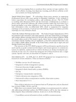
Table 3-1 is a materials check list for epoxy grouting. Orders for materials not available locally should be placed with lead time reserved for
order processing, packaging, shipping, etc. A good rule-of-thumb is to
place orders sufficiently in advance to allow three times the normal time
required for unencumbered transit, if it can be anticipated that materials
are available from stock.
All grouting materials should be stored indoors in a dry area and
preferably at room temperature. Containers stored outside may in the
summertime reach temperatures as high as 140°F, particularly if the
containers and bags are in direct sunlight. The speed of most chemical
reactions is doubled with each 10°C (18°F) rise in temperature. Consequently, it is quite probable that epoxy grout that has been stored outside
in the summertime will have an excessively hot cure. When this occurs,
the grout cures in a thermally expanded state, and after cooling, creates
locked-in stresses. Excessive cracking will result as these stresses are
relieved.
Machinery Foundations and Grouting
69
Most epoxy formulations do not cure well without accelerators at temperatures below 60°F, and not at all at temperatures below 35°F. Consequently, grouting materials stored at cold ambient temperatures require
several days to cure. When this occurs, it is possible that equipment alignment conditions will change before the mortar has set, resulting in a poor
installation. Furthermore, when the mortar is cold, it is viscous and very
difficult to place.
Conventional Grouting
Concrete Characteristics
Foundation design and machinery installation require more expertise
and precision than are usually practiced. Perhaps due to a shortage of
skilled manpower, the construction industry has given less attention to
technical details. Since there is generally some knowledge—“Everybody
knows a little bit about concrete; and aren’t foundations just big blocks of
concrete?”—grouting is often taken for granted. Consequently, a high percentage of compressors are installed improperly. Many foundations must
be renovated or the equipment regrouted long before the life of the equipment is exhausted. Here are a few common problems that can be avoided
by putting a little effort into proper design and installation.
Communication links between the equipment manufacturer, grout
manufacturer, design engineers, and construction and maintenance
personnel are poor. Equipment manufacturers sometimes provide minimum foundation mass and unbalanced forces data but they do not design
foundations. Data provided by grout manufacturers are often misinterpreted. Design engineers seldom are provided feedback data on performance of their design once the project is completed. Maintenance
personnel rarely have the opportunity to provide input during the planning
stage.
The consequences of improper installation are severe. Machinery installation costs often exceed $1,000 per horsepower and the loss of revenue
due to idle machinery has advanced at a pace even higher than the rise in
fuel costs. Large reciprocating compressor crankshafts are prone to break
if the machine is poorly supported on its foundation. Crankshafts are not
“hardware store” items. With some equipment manufacturers now relying
on foreign sources for their larger crankshafts, logistics of spare parts
supply are getting more complex. All the more reason, then, to protect the
machinery by doing an adequate grouting job.
Concrete is the most widely used construction material in the world.
Because it is so common it is often taken for granted, and therefore it has
70
Machinery Component Maintenance and Repair
Table 3-1
Materials Checklist for Epoxy Grouting
Machinery Foundations and Grouting
71
Machinery Component Maintenance and Repair
72
also become one of the most abused materials. For good foundation
design, these factors must be considered:
•
•
•
•
•
•
•
Proper chemistry
Proper water/cement ratio
A quality aggregate
Low amount of entrained air
Proper placement
An acceptable temperature range for curing
Moist curing conditions
A detailed analysis of each of these considerations would be beyond the
scope of this text; however, the listing serves to illustrate the fact that concrete is a complex material. For our purposes, a brief description of the
mechanism of concrete curing will suffice.
Concrete is composed of a graded aggregate, held together by a hardened paste of hydraulic cement and water. The thoroughly mixed ingredients, when properly proportioned, make a plastic mass which can be cast
or molded to shape, and upon hydration of the cement, becomes rock-like
in strength and hardness and has utility for many purposes, including
machinery foundations. Fresh cement paste is a plastic network of cement
particles in water. Once the paste has set, its volume remains approximately constant. At any stage of hydration the hardening paste consists of
hydrates of the various ingredients in the cement which are referred to
collectively as the “gel.” It also contains crystals of calcium hydroxide,
unhydrated cement, impurities, and water-filled spaces called capillary
pores. The gel water is held firmly and cannot move into the capillaries,
so it is not available for hydration of any unhydrated cement. Hydration
can take place only in water within the capillaries. If the capillary pores
are interconnected after the cement paste has cured, the concrete will be
permeable. The absence of interconnected capillaries is due to a combination of suitable water to cement ratio and sufficiently long moist curing
time. At least seven uninterrupted days of moist curing time are required
for machinery foundations. Even test cylinders of concrete taken at the
jobsite from the pours are often allowed to cure under water for twentyeight days before testing.
Concrete which has not been allowed to cure properly, even though
ingredients are properly mixed in the correct ratio, may be weak and
friable or it may be only slightly under ultimate strength, depending
upon the humidity and ambient temperature present when curing. Improperly cured concrete will also be permeable and therefore less resistant to degradation from lubricating oils or other materials that may be
present.
Machinery Foundations and Grouting
73
An illustration of hairline cracks caused by shrinkage of concrete during
curing can be seen in Figure 3-1 and Figure 3-2. Figure 3-1 is a photograph of the cambered surface of an airport runway which as been grooved
with a diamond saw to facilitate draining of rain water in an attempt to
reduce hydroplaning of aircraft in wet weather. In this photograph a 50
percent solution of epoxy grout liquid (without aggregate) in acetone was
poured on the surface of the runway. Note the degree of penetration into
the concrete between furrows as the solution drains away. In the photograph of Figure 3-2 the highly volatile solvent has all but evaporated from
the surface, exposing the wetted crack openings like a fingerprint. Before
wetting with the solution, cracks were invisible to the naked eye. This condition exists in most concrete machinery foundations and is caused by
water loss from the capillary pores in the concrete while curing. This water
loss causes shrinkage which would not be experienced if the concrete had
been immersed in water for 28 days like the samples from each pour that
are usually sent to the laboratory for testing. While such shrinkage cracks
do not constitute structural failure in machinery foundations, they do
provide a path for the penetration of lubricating oils into the foundation.
One interesting fact was that cored concrete samples from this runway
typically had 6,000 psi compressive strength.
It is good construction practice to seal the surface of a foundation with
a good quality epoxy paint as soon as the forms are removed. This sealing
Figure 3-1. A photograph of a cambered and grooved surface of an airport runway. Note
the degree of penetration between furrows as a low viscosity solution of epoxy adhesive in
acetone is poured on and drained away from the surface (courtesy of Adhesive Services
Company).
74
Machinery Component Maintenance and Repair
Figure 3-2. Hairline curing cracks become visible as the solvent in Figure 3-1 evaporates
from the surface (courtesy of Adhesive Services Company).
of the foundation accomplishes two objectives. First, it seals in water and
encourages more complete curing of the concrete, and second, it prevents
penetration of lubricating oils into the foundation after start-up. This
sealing is particularly important in areas such as around the oil pan trough
which are usually flooded with oil. Paint will not usually stick to concrete
unless the surface has been sandblasted to remove the laitance or unless
a penetrating primer has been applied before painting. Some specialty
coating manufacturers provide special primers for epoxy coatings when
used on concrete. Most of these special primers contain either acetone or
ketone solvents which are low in viscosity and water soluble. When utilizing these primers, care must be taken to prevent build-up of flammable
vapors and breathing or contact with eyes or skin. Read the warning labels
on the containers.
Methods of Installing Machinery1
The four common methods of installing compressors in the order of
increasing foundation load requirements are shown in Table 3-2. Static
load ranges shown in the first column are relatively low compared with
the strength of the supporting concrete. What complicates the situation is
the combination of additional anchor bolt load, dynamic load and dramatically lowered epoxy grout strength due to rising temperatures.
Machinery Foundations and Grouting
Table 3-2
Typical Loadings for the Various Methods of
Installing Compressors
75
76
Machinery Component Maintenance and Repair
Skid mounting is an equipment packaging concept whereby partial
erection of the compressor and its related equipment are carried out under
shop conditions where quality control can be closely monitored. This
concept is ideal for equipment destined for offshore or remote locations
where accessibility and accommodations are limited or where skilled manpower is not available. Packaging works well on portable units in the lower
horsepower range.
Job-site skid installation is progressively more difficult with increasing
compressor size because of the number of structural members required.
Most packagers do not provide access holes to permit grouting of internal structural members. Those internal “I” beams anchored to the equipment above are critical. Consequently, with typical factory design, grout
placement must be accomplished from the edges of the skid. Placement
of grout prepared to the proper consistency is difficult and often the critical members are left unsupported. When this occurs, a suspension bridge
effect is created, allowing excessive vibration to occur when the equipment is operating. The obvious solution to this grouting problem is to cut
access holes in the field. This should be done only with the manufacturer’s
approval, since otherwise the warranty may be voided. After grouting, all
access holes should be covered.
As mentioned earlier, most compressors leak oil. Because skids are fabricated by strip welding rather than seal welding, oil gradually seeps into
the skid cavities. To reduce this fire hazard it is common to provide openings between cavities for oil drainage. With the usual inconsistencies in
grout level, complete oil drainage is not possible. Oil degradation of
cement grouts and concrete has long been recognized. With this in mind,
skids which are to be permanently installed should be installed with epoxy
grout. Bond strength of epoxy grout helps to anchor internal structural
members that have no anchor bolts in the concrete.
The embedment method of installing machinery is by far the oldest
method. For short crankshaft gas engine compressors in the middle horsepower range, this method is preferred because it provides a “key” to resist
laterial movement. On long crankshaft equipment in the higher horsepower
range, thermal expansion of the foundation can cause crankshaft distortion
problems. Foundation expansion is uneven due to heat losses around the
outer periphery of the foundation and results in center “humping.” The
effects of humping can be avoided by installing the equipment on rails or
sole plates. The air space between the foundation and equipment provides
room for thermal growth without distorting the equipment frame. The air
space also allows some heat dissipation through convection.
Exercise caution when installing equipment on sole plates—grout properties are taxed to the absolute maximum when sole plates are designed
for static loads in the 200 psi range and then installed under equipment
Machinery Foundations and Grouting
77
with high operating or oil sump temperatures. This is particularly true
during the first few hours of operation until the grout passes through its
period of secondary curing. Refer to the typical physical properties of
epoxy grouts as shown in Table 3-3. Rails should be as short as possible
and all rails and sole plate corners should be rounded to a 2-in. radius to
minimize stress risers in the grout.
In recent years there has been a concerted effort to replace steel chocks
with epoxy chocks. This involves the use of liquid epoxy grout which is
poured in place, and after curing, forms a nonmetallic chock. One of the
advantages of this method of installing machinery is that it is not necessary to have a machined surface on the engine base in contact with the
chock. This method of engine installation has been utilized for many years
Table 3-3
Typical Physical Properties of Epoxy Grouts
78
Machinery Component Maintenance and Repair
in the marine industry on diesel engines. The forces imparted by Diesel
engines driving propulsion systems are quite different from the forces
imparted by integral gas engine compressors. For example, in the Diesel
engine propulsion system, the forces are primarily those involving torque
as imparted by the crankshaft at the output end of the engine. In integral
gas engine compressors, cyclic lateral forces, created primarily by the
compressor stages, are involved. On some compressors, the lateral forces
are so great that the engine base is fretted by steel chocks. It stands to
reason that epoxy chocks would be much less abrasion resistant than steel
chocks.
While there are numerous reports of “satisfactory installations” involving integral gas engine compressors on epoxy chocks, the fact is that this
technique has not been utilized long enough to ascertain life expectancy.
The authors are not aware of any installations where the anchor bolts have
been retorqued after several months of operation or where follow-up data
have been taken from bench marks or other datum points such as tooling
balls. In other words, the creep characteristics of epoxy chocks have not
at this time been evaluated to the satisfaction of the authors. Further, some
manufacturers do not provide test temperatures for the physical properties
reported in their technical literature. Remember, the physical properties
of epoxy grouts, unlike cement-based grouts, are reduced drastically with
rising temperatures. Because of the lack of good data and experience, this
method of installation should be classed as experimental and utilized only
at the equipment owner’s risk.
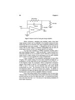
Anchor Bolts: Overview
The stretching of an anchor bolt between the bottom of the sleeve and
the bottom of the nut (Figure 3-3) is desirable to create a spring effect that
will absorb impact without fatiguing when the bolt is tightened to proper
torque. Isolating the bolt from the epoxy grout prevents bonding that can
cause temporary stretching over a short section, resulting in loose bolts
soon after start-up as the bond fatigues. Isolating the bolts also prevents
short radius flexing of the bolt if lateral movement develops. Anchor bolts
are designed for hold-down purposes and not as pins to restrict lateral
movement4.
Original Anchor Bolt Installations
It is a standard practice to install anchor bolts in a foundation at the
same time the reinforcing steel cage is fabricated and installed. Typically,
Machinery Foundations and Grouting
79
Figure 3-3. A typical anchor bolt installation which allows freedom for equipment growth
from thermal expansion.
the anchor bolts are located with the aid of a template created from engineering drawings. It should be a common practice to isolate the upper
portion of the bolt with a sleeve. The purposes of the sleeve are twofold.
First, it allows stretch of the bolt during torque application. Second, it provides a degree of freedom for the anchor bolt, which compensates for
minor positioning errors. The proper terminology for these sleeves is
“anchor bolt sleeves.” These sleeves are often, but incorrectly, referred to
as “grout sleeves.”
As mentioned earlier, grout should never be placed in anchor bolt sleeves
because bonding to the anchor bolt by the grout, particularly epoxy grout,
prevents proper stretching and defeats the main purpose of the sleeves. The
stretching of an anchor bolt between the bottom of the sleeve and the
bottom of the nut is desirable to create a spring effect that will absorb
impact without fatiguing when the bolt is tightened to proper torque. Bolt
load should be calculated to prevent separation between the bottom surface
of the nut and the machine boss when the bolts are subjected to operating
forces, and in cases involving cyclic loading, to protect the bolt from
fatigue effects of alternating tensile and compressive stresses.
Figure 3-3 is a sketch illustrating proper anchor bolt installation.
Molded polyethylene sleeves are manufactured for the popular bolt sizes.
80
Machinery Component Maintenance and Repair
They are designed so the ends of the sleeve fit tightly around the bolt in
order to center the sleeve, prevent concrete from entering the sleeve when
the concrete foundation is poured, and, at the same time, prevent water,
applied to the foundation for moist concrete curing, or rainwater from
entering the sleeve.
After the concrete has cured, the surfaces to be in contact with grout
are chipped away to expose the coarse aggregate. Immediately before positioning the equipment on the foundation, the upper end of the sleeve is
cut off even with the top of the foundation and removed. Care must be
taken to assure that water will not enter the sleeves and be allowed to
freeze and crack the foundation, particularly on outdoor installations.
After the equipment has been positioned on the foundation, leveled, and
aligned, the grout sleeves are filled with a pliable material such as a
castable polysulfide-epoxy joint sealant or closed-cell polyurethane sleeve.
Filling the sleeve with a pliable material allows for movement and
stretch, and at the same time prevents accumulation of lubricating oil in
the sleeve after equipment startup. Lubricating oil, in time, will degrade
concrete.
Figure 3-4 is a photograph illustrating the cracking of a foundation at an
anchor bolt, with the plane of the crack perpendicular to the crankshaft.
This crack was caused by grout being placed in the anchor bolt sleeve
during original construction, thereby restricting movement of the bolt.
Figure 3-5 shows the foundation after regrouting. The exposed portion
of the anchor bolt was isolated with a tubular closed-cell polyurethane
sleeve prior to repouring the epoxy grout. An expansion joint was installed
to prevent new cracks from forming. After the grout has cured and the
forms have been removed, the expansion joints and the outer periphery of
the machine base where the grout contacts the boss are sealed with oilresistant silicone rubber. The silicone provides a barrier against infiltration of oil and other liquids into the foundation.
Anchor Bolt Replacement
When anchor bolt failure is such that complete replacement is necessary, it can be accomplished using techniques consistent with the sketch
shown in Figure 3-6. This sketch is of a typical replacement anchor bolt
in an ideal installation. Complete replacement of an anchor bolt is possible without lifting or regrouting the machine. This is accomplished by
drilling large-diameter vertical holes, adjacent to the anchor bolt to be
replaced and tangent to the boss of the machine. Once the cores have been
removed, access is gained to concrete surrounding the anchor bolt. After
the surrounding concrete is chipped away, a two-piece and sleeved anchor
Machinery Foundations and Grouting
81
Figure 3-4. A photograph showing foundation cracks at an anchor bolt. This crack is in a
plane perpendicular to the crankshaft.
bolt is installed. After the replacement anchor bolt has been installed,
epoxy grout is poured to replace the concrete chipped from around the
original bolt and to replace the concrete removed by the coring.
This procedure utilizes an air-powered diamond coring machine, as
illustrated in Figure 3-7. Because the machine is air powered, it can be
used in hazardous environments without creating a danger from sparks of
open electric motors. Further, because a lot of power can be delivered by
small air motors, the size of the coring machine is relatively small. With
proper gear reduction, a hole as large as 16 inches in diameter can be
drilled with this machine. Figure 3-8 shows 12-inch-diameter cores that
have been removed with this machine. In the course of obtaining these
cores, it was necessary to core through a No. 11 (1.375≤-diameter) rebar,
a cross section of which can be seen in this illustration.
82
Machinery Component Maintenance and Repair
Figure 3-5. Foundation after regrouting. Note the expansion joint at the anchor bolt and that
the outer periphery of the machine base has been sealed with a fillet of silicone rubber.
Figure 3-6. Replacement anchor bolt.
Machinery Foundations and Grouting
83
Figure 3-7. Air-powered diamond coring machine used in replacing anchor bolts without
regrouting the machinery.
Figure 3-8. Twelve-inch-diameter cores removed in the course of complete replacement of
an anchor bolt. Note the cross section of a No. 11 rebar in the core.
Figure 3-9 depicts a dual anchor bolt installation where both anchor
bolts have been replaced and grouting is in progress. This picture was
taken after the first pour of epoxy grout. Note that sleeving has not yet
been installed on the upper stud above the coupling nut. Before the second
pour was made, a split closed-cell polyurethane sleeve was installed to
isolate the upper stud and coupling.
84
Machinery Component Maintenance and Repair
Figure 3-9. Replacement of dual anchor bolts after the first pour of epoxy grout. The
isolation sleeving has not yet been installed.
Figure 3-10. Stresses at foundation corners caused by cyclic temperature.
Outdoor Installations
Because epoxy grout and concrete absorb and dissipate heat rather
slowly, cyclic temperatures cause uneven thermal expansion or contraction. This unequal expansion produces unequal stresses. The weak link is
the tensile strength of the concrete, and cracking occurs in the corners
where stress risers exist (Figure 3-10). In Condition A, the system is in
thermal equilibrium and no stresses exist. During the cooling cycle shown
in Condition B, the grout surface contracts first. This causes a thermal gradient within the grout which produces stress that promotes edge lifting.
As the temperature conditions are reversed during the heating cycle, as
shown in Condition C, cracks have a tendency to close. As the cycle is
Machinery Foundations and Grouting
85
repeated, cracking progresses until it reaches a point under the edge of the
equipment where compressive loading exists. Because tension is required
for cracking, cracking cannot continue into an area which is under compression. Thicker grout increases the tendency for cracking until the crosssectional dimensions of grout and shoulder are about equal. After grout
thickness equals or exceeds the shoulder width, tendency for cracking is
greatly reduced due to the inflexibility of this configuration. While cracking of this nature does not cause immediate operating problems, it does
provide a path for oil to penetrate into the foundation. Over an extended
period of time support will be diminished as oil degradation of the concrete proceeds.
Cracks of this nature can be virtually eliminated by utilizing one of the
design techniques illustrated in Figure 3-11. Solution A is based on
the transfer of stress away from the corner. This technique also changes
the stress from tension to shear. Solution B transfers the stress away
from the corner to a shear area on the back side of the key. Solution
C changes the usual cross section dimensions of the shoulder, making a
relatively inflexible configuration. Other designs, such as feather edging
the grout, can be used, but all are based on eliminating stress risers at
the foundation corners.
Expansion Joints
The small differences in thermal expansion rates between concrete or
steel and an aggregate-filled epoxy grout become increasingly important
Figure 3-11. Designs to eliminate stress risers in foundation corners.
86
Machinery Component Maintenance and Repair
as the length of the grouted equipment increases. Cracking can be
expected near regions of anchor bolts or at rail or sole plate ends, unless
care is taken in the design to eliminate stress risers. This is particularly
true during equipment startup or shutdown where a temperature gradient
might be created or when brittle grouting materials are employed. For
example, during startup of rail-mounted equipment, the rails begin to grow
first as a result of thermal expansion because they are in contact with the
equipment base and conduct heat well. In order to prevent rail growth,
opposing forces must be created equal to the compressive strength of the
steel in the rail. Such forces would be well over 50 times the tensile
strength of the grout. If the grout has enough elasticity to allow rail growth
without extensive cracking, it is probably too soft to maintain support
without creep. The grout should have adequate compressive strength to
maintain alignment without creep.
The obvious solution is to install expansion joints. Expansion joints, as
shown in Figure 3-5, can be cast into the foundation when the epoxy grout
is poured. After the foundation has been dressed, the surface of the expansion joint and the outer periphery of the machine base is sealed with silicone rubber.
Postponement of Regrouting Is Risky
Real or perceived economic conditions in industry encourage postponement of routine maintenance of operating equipment. As a result,
machinery foundations fail at an increasing rate during these periods. The
most serious type of failure is foundation cracking in a plane parallel to
the crankshaft. These cracks may be caused by inadequate design or by
operating conditions that exert excessive forces on the foundation. Unless
these foundation cracks are repaired at the time of regrouting, grout life
will be greatly reduced (usually to about 10 percent of its normal life).
Lateral dynamic forces are generated by compressor pistons and by
some power pistons. Theoretically, if a machine were perfectly balanced,
there would be no forces exerted on the foundation other than dead weight.
Under such a condition, there would be no need for anchor bolts. In reality,
a perfectly balanced reciprocating machine has never been built. No experienced engineer would ever consider operating reciprocating equipment without anchor bolts.
After establishing the fact that unbalanced forces do exist on welldesigned and -maintained equipment, consider what happens when maintenance is postponed. Take the ignition system, for example. Everyone
knows what to expect from an automobile with the engine idling after one
or two spark plugs have been disconnected. Imagine the same circum-
Machinery Foundations and Grouting
87
stances with a large industrial gas engine compressor running at 100
percent capacity. Next, suppose there are lubricating oil leaks that puddle
on the foundation shoulder. If any movement exists between the machine
and grout, oil will penetrate voids caused by the movement, and hydraulically fracture any remaining bond between the machine base and grout.
As movement between the machine and grout increases, forces exerted on
the foundation increase at an exponential rate, because of change in direction and impact.
At 330 rpm there are 475,200 cycles per day. Over 20 years the foundation sees the stresses of 3.4 billion cycles. Most reciprocating equipment is expected to last more than 20 years.
The tensile strength of concrete is only about 10 percent of its compressive strength. Because of this weakness in tension, reinforcing steel
is embedded in concrete to carry the tensile loads. The placement of reinforcing steel should be chosen with consideration as to the source and
direction of the external forces applied to the foundation. According to
this reasoning, the preponderance of reinforcing steel in a reciprocating
engine/compressor foundation should be placed in the upper portion
of the block in a direction perpendicular to the crankshaft. Weighting
the placement of steel in this location would reduce the tendency for
cleavage-type failures that sometimes begin at the top of the foundation in
the notch below the oil pan and extend through the block to the mat below.
The notch provided in the top of a foundation for the oil pan creates a
perfect location for stress risers. A moment is created by lateral dynamic
forces multiplied by the distance between the machine base and the transverse reinforcing steel in the foundation below. The possibility of a foundation cracking at this location increases as the depth of the notch
increases. The further the distance between the horizontal forces and transverse reinforcing steel, the greater the moment.
Figure 3-12 illustrates a method of repairing such cracks by drilling
horizontal holes spaced from one end of the foundation to the other end.
This series of holes is placed at an elevation of just below the oil pan
trough. A high-tensile alloy steel bolt is inserted into each hole and
anchored at the bottom of the hole. Next, a small-diameter copper injection tube is placed in the annular space around the bolt; the end of the
hole is then sealed and the nut tightened to an appropriate torque to draw
the two segments of the block back together. An unfilled or liquid epoxy
is injected into the annular space around the bolt. Air in the annular space
around the bolt is pressed into the porous concrete as pressure builds. After
the annular space has been filled, injection continues, and the crack is filled
and sealed from the inside out.
This repair method places the concrete in compression, which would
otherwise be in tension. The compressive condition must be overcome
88
Machinery Component Maintenance and Repair
Figure 3-12. Method of repairing compressor foundations that are cracked parallel to the
crankshaft.
before a crack could possibly reoccur. As a result, the repaired foundation
is much stronger than the original foundation. This technique is often used
when the concrete in the foundation is of poor quality.
Preparation of Concrete Surfaces Prior to Grouting
It has been estimated that 90 percent of the heavy equipment installed
today on original installations was installed utilizing faulty grouting techniques. Because vibration and alignment problems with heavy machinery
are solved (or should be solved) in the direction from the ground up, it is
logical that grouting errors should be discussed beginning with surface
preparation of the concrete.
Many early grout failures can be attributed to poor surface preparation
of the concrete prior to grouting. Because the grouting problems associated with poor surface preparation are so widespread, it is obvious that
few understand the difference between good and poor surface preparation.
The only good method of preparing a concrete surface prior to grouting is to chip away the surface with a chipping gun to expose coarse aggregate. This means at least a minimum of 1/2≤ to 1≤ of the surface must be
removed. Poor methods of surface preparation include raking the surface
of concrete prior to curing, intermittent pecking of the surface with a chipping gun, sandblasting the surface after the concrete has cured, and rough-
Machinery Foundations and Grouting
89
ening the surface with a bushing tool (a spiked potato masher). Distinguishing between good and poor concrete surface preparation requires an
understanding of bleeding of fresh concrete pours and mechanisms involving hydration of cement. Bleeding of freshly placed concrete is a form of
separation where water in the mix tends to rise to the surface. In the course
of bleeding, some of the solid ingredients classify near the surface. Classifying of concrete ingredients is a form of sedimentation.
If the bleeding rate is faster than the evaporation rate, the rising water
brings to the surface a considerable amount of the fine cement particles,
along with any residual silt or clay that may have been present in the
aggregate.
In the course of concrete mixing, some of the hard and adherent clay
and silt coatings will be ground loose from the surface of the aggregate.
These loosened particles migrate to the surface of the concrete while the
concrete is vibrated to gain proper compaction. The migration is enhanced
by bleeding. This process promotes the formation of heavy laitance at the
surface and results in a porous, weak, and nondurable concrete surface.
If the bleeding rate is slower than the evaporation rate, the water loss
at the surface prevents proper hydration of the cement near the surface.
Improper hydration of the cement at the surface also results in a weak and
nondurable concrete surface. Further, water loss while the cement paste
is in its plastic state causes a volume change commonly known as plastic
shrinkage. While 1 percent plastic shrinkage is considered normal, excessive water loss through evaporation leads to surface cracking. Figure 3-13
illustrates proper chipping of a concrete surface prior to grouting. Note
Figure 3-13. Properly prepared concrete surface ready for grouting.