Machinery Components Maintenance And Repair Episode 1 Part 11 pps
Bạn đang xem bản rút gọn của tài liệu. Xem và tải ngay bản đầy đủ của tài liệu tại đây (509.21 KB, 25 trang )
240 Machinery Component Maintenance and Repair
Figure 5-33. Preliminary horizontal move.
Machinery Alignment 241
Figure 5-34. Preparing for the vertical move includes soft foot check.
242 Machinery Component Maintenance and Repair
Figure 5-35. Calculate the vertical move.
Machinery Alignment 243
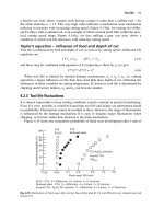
Figure 5-36. Thermal growth considerations, parallel. Thermal movements in machinery
can be graphically illustrated when the aligner knows the precalculated heat movements.
244 Machinery Component Maintenance and Repair
Figure 5-37. Thermal growth considerations, angular.
Machinery Alignment 245
Figure 5-38. Defining the “tolerance box.”
(Text continued from page 238)
the method we are about to illustrate
16
. In effect, we will see that by making
optimum movements of both elements to be aligned, the maximum move-
ment required at any point is a great deal less than if either element were
to be moved by itself. Figure 5-39 shows an electric motor-driven cen-
trifugal pump with severe vertical misalignment. The numbers are actual,
from a typical job, and were not made up for purposes of this text.
As can be seen, regardless of whether we chose to align the motor to
the pump or vice versa, we needed to lower the feet considerably—from
0.111 to 0.484 in. As it happened, the motor feet had only 0.025in. total
shimming, and the pump, as usual, had no shimming at all.
Some would shim the pump “straight up” to get it higher than the motor,
and then raise the motor as required. This, in fact, was first attempted by our
machinists. They had raised the pump about
3
/
8
in., at which point the piping
interfered, and the pump was still not high enough. By inspection of
Figures 5-41 and 5-42 it can be seen that they would have needed to raise it
0.484 in. (or 0.459 in. if all outboard motor shims had been removed).
Figure 5-42 shows the solution used to achieve alignment without
radical shimming or milling. As can be seen, our maximum shim addition
was 0.050 in., which is much lower than the values found earlier for
single-element moves. We could have reduced this shimming slightly by
removing our 0.025 in. existing shims from beneath the outboard feet
of the motor, but chose not to do so, leaving some margin for single-
element trim adjustments. As it turned out, the trimming went the other
way, with 0.012 in. and 0.014 in. additions required beneath the motor
inboard and outboard, respectively. This reflects such factors as heel-
and-toe effect causing variation in foot pivot centers. This is normal for
246 Machinery Component Maintenance and Repair
Figure 5-39. Horizontal movement by vertical adjustment: electric motor example.
Figure 5-40. Plotting board solution for electric motor movement exercise of Figure 5-39.
Machinery Alignment 247
Figure 5-41. Motor-pump vertical misalignment with single element move solutions.
situations such as this with short foot centers and long projections to
measurement planes.
Several variations on the foregoing example are worth noting, and are
shown in Figure 5-43. The basic approach is the same for all though, and
is easy to apply once the principle is understood.
We have, to this point, made no mention of thermal growth. If this is
to be considered, the growth data may be superimposed on the basic mis-
alignment plots, or included prior to plotting, before proceeding with the
optimum-move solution. Also, of course, there are valid nongraphical
methods of handling the alignment solutions shown here—but we find the
graphical approach easier for visualization, and accurate enough if done
carefully.
248 Machinery Component Maintenance and Repair
Figure 5-42. Plotting board or graph paper plot showing optimum two-element move.
Machinery Alignment 249
Figure 5-43. Various possibilities in plotting minimum displacement alignment.
Thermal Growth—Twelve Ways to Correct for It
Thermal growth of machines may or may not be significant for align-
ment purposes. In addition, movement due to pipe effects, hydraulic forces
and torque reactions may enter the picture. Relative growth of the two or
more elements is what concerns us, not absolute growth referenced to a
fixed benchmark (although the latter could have an indirect effect if piping
forces are thereby caused). Vibration, as measured by seismic or proxim-
ity probe instrumentation, can give an indication of whether thermal
growth is causing misalignment problems due to differences between
ambient and operating temperatures. If no problem exists, then a “zero-
zero” ambient alignment should be sufficient. Our experience has been
that such zero-zero alignment is indeed adequate for the majority of
electric motor driven pumps. Zero-zero has the further advantage of
simplicity, and of being the best starting point when direction of growth
is unknown. Piping is often the “tail that wags the dog,” causing growth
in directions that defy prediction. For these reasons, we favor zero-zero
unless we have other data that appear more trustworthy, or unless we are
truly dealing with a predictable hot pump thermal expansion situation.
If due to vibration or other reasons it is decided that thermal growth
correction should be applied, several approaches are available, as follows:
1. Pure guesswork, or guesswork based on experience.
2. Trial-and-error.
3. Manufacturers’ recommendations.
4. Calculations based on measured or assumed metal temperatures,
machine dimensions, and handbook coefficient of thermal
expansion.
5. Calculations based on “rules-of-thumb,” which incorporate the
basic data of 4.
6. Shut down, disconnect coupling, and measure before machines
cool down.
7. Same as 6, except use clamp-on jigs to get faster measurements
without having to break the coupling.
8. Make mechanical measurements of machine housing growth
during operation, referenced to baseplate or foundation, or between
machine elements. (Essinger.)
9. Same as 8, except use eddy current shaft proximity probes as the
measuring elements, with electronic indication and/or recording.
(Jackson; Dodd/Dynalign; Indikon.)
10. Measure the growth using precise optical instrumentation.
11. Make machine and/or piping adjustments while running, using
vibration as the primary reference.
250 Machinery Component Maintenance and Repair
12. Laser measurement represents another possibility. The OPTA-
LIGN
®
method mentioned earlier also covers hot alignment checks.
Let us now examine the listed techniques individually.
Guesswork. Guesswork is rarely reliable. Guesswork based on experi-
ence, however, may be quite all right—although perhaps in such cases it
isn’t really guesswork. If a certain thermal growth correction has been
found satisfactory for a given machine, often the same correction will
work for a similar machine in similar service.
Trial-and-Error. Highly satisfactory, if you have plenty of time to experi-
ment and don’t damage anything while doing so. Otherwise, to be avoided.
Manufacturers’ Recommendations. Variable. Some will work well, others
will not. Climatic, piping, and process service differences can, at times,
change the growth considerably from manufacturers’ predictions based on
their earlier average experience.
Calculations Based on Measured or Assumed Metal Temperatures, Machine
Dimensions, and Handbook Coefficients of Thermal Expansion.
Again,
results are variable. An infrared thermometer is a useful tool here, for
scanning a machine for temperature. This method ignores effects due to
hydraulic forces, torque reactions, and piping forces.
Calculations Based on Rules of Thumb. Same comment as previous
paragraph.
Shut Down, Disconnect Coupling, and Measure before Machines Cool Down.
About all this can be expected to do is give an indication of the credulity
of the person who orders it done. In the time required to get a set of mea-
surements by this method, most of the thermal growth and all of the torque
and hydraulic effect will have vanished.
Same as Previous Paragraph Except Use Clamp-On Jigs to Get Faster Mea-
surements Without Having to Break the Coupling.
This method, used in
combination with backward graphing, should give better results than 6,
but how much better is questionable. Even with “quick” jigs, a major part
of the growth will be lost. Furthermore, shrinkage will be occurring during
the measurement, leading to inconsistencies. Measurement of torque and
hydraulic effects will also be absent by this method. Some training courses
advocate this technique, but we do not. If used, however, three sets of data
should be taken, at close time intervals—not two sets as some texts rec-
Machinery Alignment 251
ommend. The cooling, hence shrinkage, occurs at a variable rate, and three
points are required to establish a curve for backward graphing.
Make Mechanical Measurements of Machine Housing Growth During Oper-
ation, Referenced to Baseplate or Foundation, or Between Machine Ele-
ments.
This method can be used for machines with any type of coupling,
including continuous-lube. Essinger
5
describes one variation, using base-
plate or foundation reference points, and measurement between these and
bearing housing via a long stroke indicator having Invar 36 extensions
subject to minimum expansion-contraction error. Hot and cold data are
taken, and a simple graphic triangulation method gives vertical and hori-
zontal growth at each plane of measurement. This method is easy to use,
where physical obstructions do not prevent its use. Bear in mind that base
plate thermal distortion may affect results. It is reasonably accurate, except
for some machines on long, elevated foundations, where errors can occur
due to unequal growth along the foundation length. In such cases, it may
be possible to apply Essinger’s method between machine cases, without
using foundation reference points. A further variation is to fabricate brack-
ets between machine housings and use a reverse-indicator setup, except
that dial calipers may be better than regular dial indicators which would
be bothered by vibration and bumping.
Same as Previous Paragraph, But Use Eddy Current Shaft Proximity Probes
as the Measuring Elements, with Electronic Indicating and/or Recording.
Excepting the PERMALIGN
®
method, this one lends itself the best to
keeping a continuous record of machine growth from startup to stabilized
operation. Due to the complexity and cost of the instrumentation and its
application, this technique is usually reserved for the larger, more complex
machinery trains. Judging by published data, the method gives good
results, but it is not the sort of thing that the average mechanic could be
fully responsible for, nor would it normally be justified for an average,
two-element machinery train. In some cases, high machine temperatures
can prevent the use of this method. The Dodd bars offer the advantage
over the Jackson method that cooled posts are not needed and thermal dis-
tortion of base plate does not affect results. The Indikon system also has
these advantages, and in addition can be used on unlimited axial spans. It
is, however, more difficult to retrofit to an existing machine.
Measure the Growth Using Precise Optical Instrumentation. This method
makes use of the precise tilting level and jig transit, with optical microm-
eter and various accessories. By referencing measurements to fixed ele-
vations or lines of sight, movement of machine housing points can be
determined quite accurately, while the machine is running. As with the
252 Machinery Component Maintenance and Repair
previous method, this system is sophisticated and expensive, with delicate
equipment, and requires personnel more knowledgeable than the average
mechanic. It is therefore reserved primarily for the more complex machin-
ery trains. It has given good results at times, but has also given erroneous
or questionable data in other instances. The precise tilting level has
additional use in soleplate and shaft leveling, which are not difficult to
learn.
Several consultants offer optical alignment services. For the plant
having only infrequent need for such work, it is usually more practical to
engage such a consultant than to attempt it oneself.
Make Machine and/or Piping Adjustments While Running, Using Vibration
as the Primary Reference.
Baumann and Tipping
2
describe a number of
horizontal onstream alignments, apparently made with success. Others are
reluctant to try such adjustments for fear of movement control loss that
could lead to damage. We have, however, frequently adjusted pipe sup-
ports and stabilizers to improve pump alignment and reduce vibration
while the pump was running.
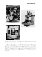
Laser Measurements
With the introduction of the modern, up-to-date PERMALIGN
®
system, laser-based alignment verification has been extended to cover hot
alignment checks. Figure 5-44 illustrates how the PERMALIGN
®
is
mounted onto both coupled machines to monitor alignment. The mea-
surements are then taken when the monitor (shown mounted on the left-
hand machine) emits a laser beam, which is reflected by the prism
mounted on the other machine (shown on the right). The reflected beam
reenters the monitor and strikes a position detector inside. When either
machine moves, the reflected beam moves as well, changing its position
in the detector. This detector information is then processed so that the
amount of machine movement is shown immediately in terms of
1
/
100
mm
or mils in the display, located directly below the monitor lens. Besides
displaying detector X and Y co-ordinates, the LCD also indicates system
temperature and other operating information.
Thermal Growth Estimation by Rules of Thumb
We will now describe several “rules of thumb” for determining growth.
Frankly, we have little faith in any of them, but are including them here
for the sake of completeness.
Machinery Alignment 253
The following is for “foot-mounted horizontal, end suction centrifugal
pumps driven by electric motors”:
For liquids 200°F and below, set motor shaft at same height as pump
shaft.
254 Machinery Component Maintenance and Repair
Figure 5-44. Hot alignment of operating
machines being verified by laser-optic
means (courtesy Prüftechnik A.G., Ismaning,
Germany).
For liquids above 200°F, set pump shaft 0.001in. lower, per 100°F of
temperature above 200°F per in. distance between pump base and shaft
centerline.
Example: 450°F liquid; pump dimension from base to centerline is
10 in.
The following applies to “foot mounted pumps or turbines”:
Where L = Distance from base to shaft centerline, feet
T
o
= Operating temperature, °F
T
a
= Ambient temperature, °F
For centerline mounted pumps, we are told to change the coefficient
from 6 to 3. Another rule tells us to use the coefficient 3 for foot mounted
pumps!
Yet another source tells us to use the following formula:
Another rule of thumb says to neglect thermal growth in centerline
mounted pumps when fluid temperature is below 400°F, and to cool the
pedestal when fluid temperature exceeds 400°F. This rule is somewhat
unrealistic, since the benefits of omitting the cooling clearly outweigh the
advantages of including it!
Yet another rule tells us to allow for 0.0015in. growth per in. of height
from base to shaft centerline, for any steam turbine—regardless of steam
or ambient temperatures. Another chart goes into elaborate detail, recom-
mending various differences in centerline height between turbine and
pump based on machine types and service conditions, but without con-
sidering their dimensions.
Therma
TT L
for
oa
l growth, inches,
centerline mounted pumps
.
For foot mounted pumps, use L in place of
L
3
=¥
-
()
¥0 008
100 3
.,
.
Therma
TT
L
oa
l growth mils
()
=¥
-
()
¥6
100
450 200
100
0 001 10 0 025
-
()
()()
=
()
.
in
or
Therefore, set pump 0.025in. low
set motor 0.025in. high
Machinery Alignment 255
For electric motor growth, we have the following:
(Foot to shaft centerline, in.) (6 ¥ 10
-6
) (nameplate temp rise, °F) =
motor vertical growth, in. This is inconvenient, since motor temperature
rise is normally given in degrees centigrade. In case you have forgotten
how to convert, °F = (°C ¥ 9/5) + 32.
Another rule says to use half of the above figure.
Then there is the rule that advises using 7 L, where L represents dis-
tance from base to shaft centerline in feet, and the answer comes out in
thousandths of an inch. Yet another source says to use 4L. These rules all
assume uniform vertical expansion from one end to the other. However,
on motors having single end fans, the expansion will be greater at the air
outlet end. Angular misalignment caused by this difference can exceed
parallel misalignment caused by overall growth! The same can be true of
certain other machines with a steep temperature gradient from one end to
the other, such as blowers, compressors, and turbines.
The rules just cited were found in various published or filmed instruc-
tions from major pump manufacturers, oil refining companies and, in one
case, a technical magazine published for the electric power industry. Their
inconsistency, and their failure to recognize certain growth phenomena,
make their accuracy rather questionable. This is especially true where
piping growth can affect machine alignment.
Finally, the reader may wish to review either ref. 17 or 18, which give
quick updates on shaft alignment technology.
References
1. Alignment Procedure, Revised Edition. Buffalo, New York, Joy Man-
ufacturing Company, 1970. (This describes and illustrates a mathe-
matical formula progressive calculation approach to determining
corrective movements based on reverse-indicator measurements.)
2. Baumann, Nelson P. and Tipping, William E., Jr., “Vibration Reduc-
tion Techniques for High-Speed Rotating Equipment—ASME Paper
65-WA/PWR-3.” New York: The American Society of Mechanical
Engineers, 1965.
3. Dodd, V. R., Total Alignment. The Petroleum Publishing Company,
Tulsa, 1975.
4. Dreymala, James, Factors Affecting and Procedures of Shaft Align-
ment. Dreyco Mechanical Services, Houston, 1974.
5. Essinger, Jack N., “Alignment of Turbomachinery—A Review of
Techniques Employing Dial Indicators.” Paper presented at Second
Symposium on Compressor Train Reliability Improvement, Manu-
facturing Chemists Association, Houston, Texas, April 4, 1972.
256 Machinery Component Maintenance and Repair
Similar information was published in Hydrocarbon Processing, Sep-
tember 1973.
6. Gibbs, C. R. and Wren, J. R., “Aligning Horizontal Machine Sets.”
Allis-Chalmers Engineering Review. About 1968—exact date not
known.
7. Jackson, Charles, “How to Align Barrel-Type Centrifugal Compres-
sors.” Hydrocarbon Processing (September 1971) (Corrected
Reprint).
8. Jackson, Charles, “Start Cold for Good Alignment of Rotating Equip-
ment.” The Oil and Gas Journal, March 11, 1974, Pages 124–130.
9. Jackson, Charles, “Techniques for Alignment of Rotating Equip-
ment.” Hydrocarbon Processing, LV (January 1976), Pages 81–86.
10. King, W. F. and Petermann, J. E., “Align Shafts, Not Couplings!”
Allis-Chalmers Electrical Review. Second Quarter 1951, Pages
26–29.
11. Nelson, Carl A., “Orderly Steps Simplify Coupling Alignment.” Plant
Engineering, June 1967, Pages 176–178.
12. “Service Memo SD-5-69; Reverse Reading Coupling Alignment.”
Houston: Dresser Industries, Inc., Machinery Group, 1969.
13. Durkin, Tom, “Aligning Shafts.” Plant Engineering, January 11,
1979, Pages 86–90, and February 8,1979, Pages 102–105.
14. Zatezalo, John, “A Machinery Alignment System for Industry.” Pitts-
burgh: IMS–Industrial Maintenance Systems, Inc., 1981.
15. Hamar, Martin R., “Laser Alignment in Industry–ASTME Paper
MR68–408.” Dearborn, Michigan: The American Society of Tool and
Manufacturing Engineers, 1968.
16. Murray, Malcolm G., “Out of Room? Use Minimum Movement
Machinery Alignment.” Hydrocarbon Processing, Houston, January
1979, Pages 112–114.
17. Bloch, Heinz P., “Updating Shaft Alignment Knowledge.” Mainte-
nance Technology, April 2004.
18. Bloch, Heinz P., “Update Your Shaft Alignment Knowledge.” Chem-
ical Engineering, September 2004.
Machinery Alignment 257
Chapter 6
Balancing of Machinery
Components*
This chapter contains some of the theoretical aspects of balancing and
balancing machines, to give a better understanding of the process of
balancing a rotor and of the working principles of balancing machines
1,2
.
Definition of Terms
Definitions of many terms used in balancing literature and in this text
are contained in Appendix A. Commonly used synonyms for some of these
standard terms are also included. For further information on terminology,
refer to ISO Standard No. 1925 (see Appendix 6C).
Purpose of Balancing
An unbalanced rotor will cause vibration and stress in the rotor itself
and in its supporting structure. Balancing of the rotor is therefore neces-
sary to accomplish one or more of the following:
1. Increase bearing life.
2. Minimize vibration.
3. Minimize audible and signal noises.
4. Minimize operating stresses.
5. Minimize operator annoyance and fatigue.
258
* Copyright Schenck Trebel Corporation, Deer Park, New York. Adapted by permission.
6. Minimize power losses.
7. Increase quality of product.
8. Satisfy operating personnel.
Unbalance in just one rotating component of an assembly may cause
the entire assembly to vibrate. This induced vibration in turn may cause
excessive wear in bearings, bushings, shafts, spindles, gears, etc., sub-
stantially reducing their service life. Vibration sets up highly undesirable
alternating stresses in structural supports and frames that may eventually
lead to their complete failure. Performance is decreased because of the
absorption of energy by the supporting structure. Vibrations may be trans-
mitted through the floor to adjacent machinery and seriously impair its
accuracy or proper functioning.
The Balancing Machine as a Measuring Tool
A balancer or balancing machine is necessary to detect, locate, and
measure unbalance. The data furnished by the balancer permit changing
the mass distribution of a rotor, which, when done accurately, will balance
the rotor. Balance is a zero quantity, and therefore is detected by observ-
ing an absence of unbalance. The balancer measures only unbalance, never
balance.
Centrifugal force acts upon the entire mass of a rotating element,
impelling each particle outward and away from the axis of rotation in a
radial direction. If the mass of a rotating element is evenly distributed
about its shaft axis, the part is “balanced” and rotates without vibration.
However, if an excess of mass exists on one side of a rotor, the centrifu-
gal force acting upon this heavy side exceeds the centrifugal force exerted
by the light side and pulls the entire rotor in the direction of the heavy
side. Figure 6-1 shows the side view of a rotor having an excess mass m
on one side. Due to centrifugal force exerted by m during rotation, the
entire rotor is being pulled in the direction of the arrow F.
Causes of Unbalance
The excess of mass on one side of a rotor shown in Figure 6-1 is called
unbalance. It may be caused by a variety of reasons, including:
1. Tolerances in fabrication, including casting, machining, and assembly.
2. Variation within materials, such as voids, porosity, inclusions, grain,
density, and finishes.
Balancing of Machinery Components 259
3. Nonsymmetry of design, including motor windings, part shapes,
location, and density of finishes.
4. Nonsymmetry in use, including distortion, dimensional changes, and
shifting of parts due to rotational stresses, aerodynamic forces, and
temperature changes.
Often, balancing problems can be minimized by symmetrical design
and careful setting of tolerances and fits. Large amounts of unbalance
require large corrections. If such corrections are made by removal of
material, additional cost is involved and part strength may be affected.
If corrections are made by addition of material, cost is again a factor and
space requirements for the added material may be a problem.
Manufacturing processes are the major source of unbalance. Unma-
chined portions of castings or forgings which cannot be made concentric
and symmetrical with respect to the shaft axis introduce substantial unbal-
ance. Manufacturing tolerances and processes which permit any eccen-
tricity or lack of squareness with respect to the shaft axis are sources of
unbalance. The tolerances, necessary for economical assembly of several
elements of a rotor, permit radial displacement of assembly parts and
thereby introduce unbalance.
Limitations imposed by design often introduce unbalance effects which
cannot be corrected adequately by refinement in design. For example, elec-
trical design considerations impose a requirement that one coil be at a
greater radius than the others in a certain type of universal motor armature.
It is impractical to design a compensating unbalance into the armature.
260 Machinery Component Maintenance and Repair
Figure 6-1. Unbalance causes centrifugal force.
Fabricated parts, such as fans, often distort nonsymmetrically under
service conditions. Design and economic considerations prevent the adap-
tation of methods which might eliminate this distortion and thereby reduce
the resulting unbalance.
Ideally, rotating parts always should be designed for inherent balance,
whether a balancing operation is to be performed or not. Where low
service speeds are involved and the effects of a reasonable amount of
unbalance can be tolerated, this practice may eliminate the need for bal-
ancing. In parts which require unbalanced masses for functional reasons,
these masses often can be counterbalanced by designing for symmetry
about the shaft axis.
A rotating element having an uneven mass distribution, or unbalance,
will vibrate due to the excess centrifugal force exerted during rotation by
the heavier side of the rotor. Unbalance causes centrifugal force, which in
turn causes vibration. When at rest, the excess mass exerts no centrifugal
force and, therefore, causes no vibration. Yet, the actual unbalance is still
present.
Unbalance, therefore, is independent of rotational speed and remains
the same, whether the part is at rest or is rotating (provided the part does
not deform during rotation). Centrifugal force, however, varies with speed.
When rotation begins, the unbalance will exert centrifugal force tending
to vibrate the rotor. The higher the speed, the greater the centrifugal force
exerted by the unbalance and the more violent the vibration. Centrifugal
force increases proportionately to the square of the increase in speed. If
the speed is doubled, the centrifugal force quadruples; if the speed is
tripled, the centrifugal force is multiplied by nine.
Units of Unbalance
Unbalance is measured in ounce-inches, gram-inches, or gram-
millimeters, all having a similar meaning, namely a mass multiplied by its
distance from the shaft axis. An unbalance of 100g·in., for example, indi-
cates that one side of the rotor has an excess mass equivalent to 10 grams
at a 10 in. radius, or 20 grams at a 5in. radius (see Figure 6-2).
In each case, the mass, when multiplied by its distance from the shaft
axis, amounts to the same unbalance value, namely 100 gram-inches. A
given mass will create different unbalances, depending on its distance
from the shaft axis. To determine the unbalance, simply multiply the mass
by the radius.
Since a given excess mass at a given radius represents the same unbal-
ance regardless of rotational speed, it would appear that it could be cor-
rected at any speed, and that balancing at service speeds is unnecessary.
Balancing of Machinery Components 261
This is true for rigid rotors as listed in Table 6-5. However, not all rotors
can be considered rigid, since certain components may shift or distort
unevenly at higher speeds. Thus they may have to be balanced at their
service speed.
Once the unbalance has been corrected, there will no longer be any sig-
nificant disturbing centrifugal force and, therefore, no more unbalance
vibration. A small residual unbalance will usually remain in the part, just
as there is a tolerance in any machining operation. Generally, the higher
the service speed, the smaller should be the residual unbalance.
In many branches of industry, the unit of gram · inch (abbreviated g · in.)
is given preference because it has proven to be the most practical. An
ounce is too large for many balancing applications, necessitating fractions
or a subdivision into hundredths, neither of which has become very
popular.
Types of Unbalance
The following paragraphs explain the four different types of unbalance
as defined by the internationally accepted ISO Standard No. 1925 on bal-
ancing terminology. For each of the four mutually exclusive cases an
example is shown, illustrating displacement of the principal axis of inertia
from the shaft axis caused by the addition of certain unbalance masses in
certain distributions to a perfectly balanced rotor.
Static Unbalance
Static unbalance, formerly also called force unbalance, is illustrated in
Figure 6-3 below. It exists when the principal axis of inertia is displaced
parallel to the shaft axis. This type of unbalance is found primarily in
262 Machinery Component Maintenance and Repair
Figure 6-2. Side view of rotors with 100 g ·in. unbalance.
narrow, disc-shaped parts such as flywheels and turbine wheels. It can be
corrected by a single mass correction placed opposite the center-of-gravity
in a plane perpendicular to the shaft axis, and intersecting the CG.
Static unbalance, if large enough, can be detected with conventional
gravity-type balancing methods. Figure 6-3A shows a concentric rotor
with unbalance mass on knife edges. If the knife-edges are level, the rotor
will turn until the heavy or unbalanced spot reaches the lowest position.
Figure 6-3B shows an equivalent condition with an eccentric rotor. The
rotor with two equal unbalance masses equidistant from the CG as shown
in Figure 6-3C is also out of balance statically, since both unbalance
masses could be combined into one mass located in the plane of the CG.
Static unbalance can be measured more accurately by centrifugal means
on a balancing machine than by gravitational means on knife-edges or
rollers. Static balance is satisfactory only for relatively slow-revolving,
disc-shaped parts or for parts that are subsequently assembled onto a larger
rotor which is then balanced dynamically as an assembly.
Couple Unbalance
Couple unbalance, formerly also called moment unbalance, is illus-
trated in Figure 6-4 and 6-4A. It is that condition for which the principal
axis of inertia intersects the shaft axis at the center of gravity. This arises
when two equal unbalance masses are positioned at opposite ends of a
rotor and spaced 180° from each other. Since this rotor will not rotate
when placed on knife-edges, a dynamic method must be employed to
detect couple unbalance. When the workpiece is rotated, each end will
vibrate in opposite directions and give an indication of the rotor’s uneven
mass distribution.
Couple unbalance is sometimes expressed in gram · inch · inches or
gram · in.
2
(or ounce-in.
2
), wherein the second in. dimension refers to the
distance between the two planes of unbalance.
Balancing of Machinery Components 263
Figure 6-3. Static unbalance.
264 Machinery Component Maintenance and Repair
Figure 6-3A. Concentric disc with static unbalance.
Figure 6-3B. Eccentric disc, therefore static unbalance.
Figure 6-3C. Two discs of equal mass and identical static unbalance, aligned to give
statically unbalanced assembly.
It is important to note that couple unbalance cannot be corrected by a
single mass in a single correction plane. At least two masses are required,
each in a different transverse plane (perpendicular to the shaft axis) and
180° opposite to each other. In other words, a couple unbalance needs
another couple to correct it. In the example in Figure 6-4B, for instance,
correction could be made by placing two masses at opposite angular posi-
tions on the main body of the rotor. The axial location of the correction