Machinery Components Maintenance And Repair Episode 2 Part 9 pps
Bạn đang xem bản rút gọn của tài liệu. Xem và tải ngay bản đầy đủ của tài liệu tại đây (262.02 KB, 25 trang )
•
Journal surface—Surfaces that have been scratched, pitted, or
scraped to depths of 0.001 in. or less are acceptable for use.
Deeper imperfections in the range of 0.001 to 0.005 in. must
be restored by strapping.
•
Thrust collar—does it have good finish? Use same guidelines
as for journals. Is the locking nut and key tight? If the collar
is removed, is its fit proper? It should have 0.001 to 0.0005in.
interference minimum.
3. The journals, coupling fits, overspeed trip, and other highly pol-
ished areas should be tightly wrapped and sealed with protective
cloth.
4. The rotor should be sandblasted using No. 5 grade, 80/120 mesh,
polishing compound, silica sand, or aluminum oxide.
5. When the rotor is clean, it should be again visually inspected.
6. Impellers and shaft sleeve rubs—rubs in excess of 5mils deep in
labyrinth areas require reclaiming of that area.
7. Wheel location—have any wheels shifted out of position? Wheel
location should be measured from a thrust collar locating shoulder.
There should be a 4–5 mil gap between each component of the
rotor; i.e., each impeller, each sleeve, etc.
8. On areas suspected of having heat checking or cracks, a dye pene-
trant check should be made using standard techniques or “Zyglo”:
a. Preparation
Cracks in forgings probably have breathed; that is, they have
opened and closed during heat cycles, drawing in moist air that
has condensed in the cracks, forming oxides and filling cracks
with moisture. This prevents penetration by crack detection
solutions. To overcome this condition, all areas to be tested
should be heated by a gas torch to about 250°F and allowed to
cool before application of the penetrant.
These tests require a smooth surface as any irregularities will
trap penetrant and make it difficult to remove, thus giving a false
indication or obscuring a real defect.
b. Application
The penetrant is applied to the surface and allowed to seep into
cracks for 15 to 20 minutes. The surface is then cleaned and a
developer applied. The developer acts as a capillary agent (or
blotter) and draws the dyed penetrant from surface defects so it
is visible, thus indicating the presence of a discontinuity of the
surface. In “Zyglo” an ultraviolet light is used to view the
surface.
9. A more precise method of checking for a forging defect would
require magnetic particle check, “Magnaflux” or “Magnaglow.” As
Centrifugal Compressor Rotor Repair 515
these methods induce a magnetic field in the rotor, care must be
taken to ensure that the rotor is degaussed and all residual mag-
netism removed.
10. The rotor should be indicated with shaft supported at the journals:
a. Shaft run out (packing areas) 0.002 in. TIR max.
b. Impeller wobble—0.010 in. TIR—measured near O.D.
c. Shroud band wobble—0.020 in. TIR.
d. Thrust collar—0.0005 in. TIR measured on vertical face.
e. Vibration probe surfaces 0.0005 in. TIR—no chrome plating,
metallizing, etc., should be permitted in these areas.
f. Journal areas—0.0005 in. TIR, 20 micro in. rms or better.
g. Gaps between all adjacent shrink fit parts—should be 0.004 to
0.005 in.
11. If the shaft has a permanent bow in excess of the limit or if there
is evidence of impeller distress, i.e., heavy rubs or wobble, the rotor
must be disassembled. Similarly, if the journals or seal surfaces on
the shaft are badly scored, disassembly in most cases is indicated
as discussed below.
Disassembly of Rotor for Shaft Repair
If disassembly is required the following guidelines will be helpful.
1. The centrifugal rotor assembly is made with uniform shrink fit
engagement (
3
/
4
to 1
1
/
2
mil/in. of shaft diameter), and this requires an
impeller heating process or, in extreme cases, a combination process
of heating the impeller and cooling the shaft.
2. The shrinks are calculated to be released when the wheel is heated
to 600°F maximum. To exceed this figure could result in metallurgi-
cal changes in the wheel. Tempil
®
sticks should be used to ensure
this is not exceeded. The entire diameter of an impeller must be uni-
formly heated using “Rosebud” tips—two or more at the same time.
3. Generally a turbine wheel must be heated so that it expands
0.006–0.008 in. more than the shaft so that it is free to move on the
shaft.
4. The important thing to remember when removing impellers is that
the heat must be applied quickly to the rim section first. After the
rim section has been heated, heat is applied to the hub section, start-
ing at the outside. Never apply heat toward the bore with the remain-
der of the impeller cool.
5. To disassemble rotors, naturally the parts should be carefully marked
as taken apart so that identical parts can be replaced in the proper
516 Machinery Component Maintenance and Repair
position. A sketch of rotor component position should be made using
the thrust collar as a reference point. Measure and record distance
from the thrust collar or shoulder to first impeller hub edge. Make
and record distance between all impellers.
6. When a multistage compressor is to be disassembled, each im-
peller should be stencilled. From thrust end, the first impeller
should be stencilled T-1, second wheel T-2, and so on. If working
from coupling end, stencil first wheel C-1, second wheel C-2, and
so on.
7. The rotor should be suspended vertically above a sand box to soften
the impact of the impeller as it falls from the shaft. It may be nec-
essary to tap the heated impeller with a lead hammer in order to get
it moving. The weight of the impeller should cause it to move when
it is hot enough.
Shaft Design
It is not uncommon to design for short-term loads approaching 80
percent of the minimum yield strength at the coupling end of the shaft.
The shaft is not exposed to corrosive conditions of the compressed gas at
this point. Inside of the casing, the shaft size is fixed by the critical speed
rigidity requirements. The internal shaft stress is about 5,000–7,000 psi—
very low compared to the impellers or at the coupling area. With drum-
type rotors there is no central portion of the shaft, there are only shaft
stubs at each end of the rotor. The purpose of the shaft is to carry the
impellers, to bridge the space between the bearings and to transmit the
torque from the coupling to each impeller. Another function is to provide
surfaces for the bearing journals, thrust collars, and seals.
The design of the shaft itself does not present a limiting factor in the
turbomachinery design. The main problems are to maintain the shaft
straight and in balance, to prevent whipping of overhangs, and to prevent
failure which may be caused by lateral or torsional vibration, chafing of
shrunk-on parts, or manufacturing inadequacies. The shaft must be accu-
rately made, but the limits of technology are not approached as far as
theory or manufacturing techniques are concerned. A thermally unstable
shaft develops a bow as a function of temperature. To reduce this bow to
acceptable limits requires forgings of a uniformity and quality that can
only be obtained by the most careful manufacturing and metallurgical
techniques.
Rotors made of annealed material are not adequate, because many mate-
rials, for example AISI 4140, have a high ductility transition temperature
in the annealed condition. This has caused failures, especially of shaft
Centrifugal Compressor Rotor Repair 517
ends. Therefore, it is very important to make sure that the material has
been properly heat-treated.
Most compressor shafts are made from AISI 4140 or 4340. AISI 4340
is preferred because the added nickel increases the ductility of the metal.
Most of the time the yield strength is over 90,000psi and the hardness no
greater than 22 Rockwell “C” in order to avoid sulfide stress cracking.
While selection of the material is fairly simple, quality control over the
actual piece of stock is complicated. There are several points to consider.
1. Material Quality: Forgings of aircraft quality (= “Magnaflux
quality”) are required for all but the simplest machines. Bar-stock
may not have sufficient thermal stability, and therefore must be
inspected carefully. Note that shafts—as well as all other critical
components—must be stress-relieved after rough machining, which
usually leaves
1
/
16
in. of material for finishing.
2. Testing: Magnaglow of finished shaft. Ultrasonic test is desirable for
large shafts. Heat indication test is required for critical equipment.
3. Shaft Ends: Should be designed to take a moderate amount of tor-
sional vibration, not only the steady operating torque.
4. The shaft must be able to withstand the shrink stresses. Any medium
strength steel will do this. After some service the impeller hubs coin
distinct depressions into such shafts, squeezing the shaft, so to speak.
This squeezing process also causes shaft distortion and permanent
elongation of the shaft, which can lead to vibration problems or inter-
nal rubbing. Since part of the initial shrink fit is lost, this may cause
other types of problems, such as looseness of impellers, which then
can lead to looseness-excited vibrations such as hysteresis whirl.
Rotor Assembly
1. Remove the balanced shaft from the balancing machine, and
position it vertically in a holding fixture providing adequate lateral
support; the stacking step on the shaft should be at the bottom.
2. Remove all of the half-keys.
3. Assembly of the impellers and spacers on the shaft requires heating,
generally in accordance with the procedure previously outlined for
mandrel balancing. The temperature that must be attained to permit
assembly is determined by the micrometer measurement of the
shaft and bore diameters, and calculation of the temperature dif-
ferential needed.
4. Due to extreme temperatures, a micrometer cannot be used; there-
fore, a go-no go gauge, 0.006 in. to 0.008 in. larger than the shaft
518 Machinery Component Maintenance and Repair
diameter at the impeller fit, should be available for checking the
impeller bore before any assembly shrinking is attempted.
5. Shrink a ring (0.003 in. to 0.004 in. tight) on the shaft extending
about
1
/
32
in. past the first impeller location. Machine the ring to the
exact distance from the machined surface of the impeller to the
thrust shoulder, and record it on a sketch. This gives a perfect loca-
tion and helps make the impeller run true.
6. Heating the impeller for assembly is a critical step. The important
thing to keep in mind is that the hub bore temperature must not get
ahead of the rim temperature by more than 10°–15°F. The usual
geometry of impellers is such that they will generally be heated so
that the rim will expand slightly ahead of the hub section and tend
to lift the hub section outward. With long and heavy hub sections,
extreme care must be taken to not attempt too rapid a rate of heating
because the bore of the hub can heat up ahead of the hub section
and result in a permanent inward growth of the bore.
Heating of the wheel can be accomplished in three different
ways:
a. Horizontal furnace: the preferred method of heating the wheel
for assembly because the temperature can be carefully controlled.
b. Gas ring: The ring should be made with a diameter equal to the
mass center of the impeller.
c. “Rosebuds”: The use of two or more large diameter oxyacety-
lene torches can be used with good results. The impeller should
be supported at three or more points. Play the torches over the
impeller so that it is heated evenly, remembering the 600°F limi-
tation. Tempil
®
sticks should be used to monitor the temperature.
7. The wheel fit of the shaft should be lightly coated with high tem-
perature antiseize compound.
8. The heated wheel should be bore checked at about the center of
the bore fits. As soon as a suitable go-no go gauge can be inserted
freely into the impeller fit bore, the impeller should be quickly
moved to the shaft. With the keys in place, the impeller bore should
be quickly dropped on the shaft, using the ring added in step 5 as
a locating guide.
9. Shim stock, of approximately 0.004–0.006 in. thickness, should
be inserted at three equally-spaced radial locations adjacent to the
impeller hubs to provide the axial clearance needed between adja-
cent impellers. This is necessary to avoid transient thermal bowing
in service.
10. Artificial cooling of the impeller during assembly must be used
in order to accurately locate the impeller at a given fixed axial
position. Compressed air cooling must be immediately applied after
Centrifugal Compressor Rotor Repair 519
the wheel is in place. The side of the impeller where air cooling is
applied is nearest to the fixed locating ring and/or support point. The
locating ring should be removed after the impeller is cooled.
11. Recheck axial position of the impeller. If an impeller goes on out
of position and must be moved, thoroughly cool the entire impeller
and shaft before starting the second attempt. This may take three
to four hours.
12. After the impellers, with their spacers and full-keys, have been
assembled and cooled, the shim stock adjacent to the impeller hubs
should be removed.
13. If the rotor has no sleeves, another split ring is needed to locate the
second impeller. This split ring is machined to equal the distance
between the first and second wheels. Then, a split ring is required for
the next impeller, etc. Any burrs raised by previously assembled im-
pellers should be carefully removed and the surfaces smoothed out.
14. Check for shaft warpage and impeller runout as each impeller is
mounted. It may be necessary to unstack the rotor to correct any
deficiencies.
15. The mounting of sleeves and thrust collars requires special atten-
tion. Sleeves have a lighter shrink than wheels and because of their
lighter cross section can be easily damaged by uneven heating or
high temperature. Thrust collars can be easily warped by heat. The
temperature of the thrust collar and sleeves should be limited to
about 300°–400°F.
16. Mount the rotor, now containing all the impellers, in the balancing
machine, and spin it at the highest possible speed for approximately
five minutes.
17. Shut down and check the angular position of the high spots and
runout at the three previously selected spacer locations between
journals. The high spots must be within ±45°, and the radial run-
outs within
1
/
2
mil, of the values recorded during bare shaft check-
ing. If these criteria are not satisfied, it indicates that one or more
elements have been cocked during mounting, thus causing the shaft
to be locked-up in a bow by the interference fits. It is then neces-
sary to remove the two impellers and spacers from the shaft, and
to repeat the vertical assembly process.
18. Install the rotor locknut, being careful not to over tighten it; shaft
bowing can otherwise result. If the rotor elements are instead posi-
tioned by a split ring and sleeve configuration, an adjacent spacer
must be machined to a precise length determined by pin microme-
ter measurement after all impellers have been mounted.
19. Many compressors are designed to operate between the 1st and
2nd lateral critical speeds. Most experts agree that routine check
520 Machinery Component Maintenance and Repair
balance of complete rotors with correction on the first and last
wheels is wrong for rotors with more than two wheels. The best
method is to balance the assembled rotor in three planes.
The residual dynamic couple imbalance should be corrected at the
ends of the rotor, and the remaining residual static (force) imbal-
ance should be corrected at about the middle of the rotor.
For compressors that operate below the first critical (stiff shaft
machines), two plane balance is satisfactory.
20. Install the thrust disc on the rotor; this should require a small
amount of heating. It is most important that cold clearances not
exist at the thrust disc bore, since it will permit radial throwout
of a relatively large mass at operating speed. Install the thrust-
bearing spacer, and lightly tighten the thrust-bearing locknut.
21. Spin the rotor at the highest possible balancing speed, and identify
the correction(s) required at the thrust-bearing location. Generally,
a static correction is all that is necessary, and it should be made in
the relief groove at the OD of the thrust disc. No correction is
permitted at the opposite end of the rotor.
22. Check the radial runout of the shaft end where the coupling hub
will mount. This runout must not exceed 0.0005in. (TIR), as
before.
Shaft Balancing
Despite its symmetrical nature the shaft must be balanced. Again, the
reader may wish to refer to Chapter 6 for details on the following.
1. Prepare half-keys for the keyways of the bare shaft. These should be
carefully taped in position, using high-strength fiber-impregnated
tape; several turns are usually required.
Note: Tape sometimes fails during spinning in the balancing
machine. It is therefore important that adequate shields be
erected on each side of the balancing machine for the pro-
tection of personnel against the hazard of flying half-keys.
2. Mount the bare shaft, with half-keys in place, in the balancing
machine with the supports at the journal locations. Spin the bare
shaft at a speed of 300–400 rpm for approximately ten minutes. Shut
down, and check the radial runout (TIR) at mid-span using a
1
/
10
mil
dial indicator; record the angular position of the high spot and run
out valve. Spin the bare shaft at a speed of 200–300rpm for an
Centrifugal Compressor Rotor Repair 521
additional five minutes. Shut down, and again check the radial run-
out (TIR) at mid-span; record the angular position of the high spot
and runout valve. Compare the results obtained after the ten minute
and five minute runs; if they are the same, the bare shaft is ready for
further checking and balancing. If the results are not repetitive, addi-
tional spinning is required; this should be continued until two con-
secutive five minute runs produce identical results.
3. Check the radial run-out (TIR) of the bare shaft in at least three
spacer locations, approximately equidistant along the bearing span,
and near the shaft ends. Record the angular position of the high spots
and the runout values at each location. The shaft is generally con-
sidered to be satisfactory if both of these conditions are satisfied:
a. The radial runout (TIR) at the section of the shaft between jour-
nals does not exceed 0.001in.
b. The radial runout (TIR) outboard of the journals does not exceed
0.0005 in.
4. With the balancing machine operating at its pre-determined rpm,
make the required dynamic corrections to the bare shaft using wax.
When satisfactory balance is reached, start removing material at the
face of the step at each end of the center cylindrical section of the
shaft. Under no circumstances should material be removed from
the sections of the shaft outboard of the journal bearings.
Rotor Thrust in Centrifugal Compressors
Thrust bearing failure has potentially catastrophic consequences in
compressors. Almost invariably, failure is due to overloading because of
the following:
1. Improper calculation of thrust in the design of the compressor.
2. Failure to calculate thrust over the entire range of operating
conditions.
3. A large increase in thrust resulting from “wiping” of impeller and
balance piston labyrinth seals.
4. Surging of machine so that rotor “slams” from one side of thrust
bearing to the other, and the oil film is destroyed.
5. Thrust collar mounting design is inadequate.
Rotor Thrust Calculations
Thrust loads in compressors due to aerodynamic forces are affected by
impeller geometry, pressure rise through the compressor, and internal
522 Machinery Component Maintenance and Repair
leakage due to labyrinth clearances. The impeller thrust is calculated,
using correction factors to account for internal leakage and a balance
piston size selected to compensate for the impeller thrust load. The
common assumptions made in the calculations are as follows:
1. Radial pressure distribution along the outside of disc cover is essen-
tially balanced.
2. Only the “eye” area is effective in producing thrust.
3. Pressure differential applied to “eye” area is equal to the difference
between the static pressure at the impeller tip, corrected for the
“pumping action” of the disc, and the total pressure at inlet.
These “common assumptions” are grossly erroneous and can be disas-
trous when applied to high pressure barrel-type compressors where a large
part of the impeller-generated thrust is compensated by a balance piston.
The actual thrust is about 50 percent more than the calculations indicate.
The error is less when the thrust is compensated by opposed impellers,
because the mistaken assumptions offset each other.
Magnitude of the thrust is considerably affected by leakage at impeller
labyrinth seals. Increased leakage here produces increased thrust inde-
pendent of balancing piston labyrinth seal clearance or leakage. A very
good discussion of thrust action is found in Reference 3.
The thrust errors are further compounded in the design of the bal-
ancing piston, labyrinths, and line. API-617, “Centrifugal Compressors,”
specifies that a separate pressure tap connection shall be provided to indi-
cate the pressure in the balance chamber. It also specifies that the balance
line shall be sized to handle balance piston labyrinth gas leakage at twice
initial clearance without exceeding the load ratings of the thrust bearing,
and that thrust bearings for compressors should be selected at no more
than 50 percent of the bearing manufacturer’s rating.
Many compressor manufacturers design for a balancing piston leakage
rate of about 1
1
/
2
–2 percent of the total compressor flow. Amoco and others
feel that the average compressor, regardless of vendor, has a leakage rate
of 3–4 percent of the total flow, and the balance line must be sized accord-
ingly. This design philosophy would dictate a larger balance line to take
care of the increased flow than normally provided. The balancing chamber
in some machines is extremely small and probably highly susceptible to
eductor type action inside the chamber which can increase leakage and
increase thrust action. The labyrinth’s leakage should not be permitted to
exceed a velocity of 10 ft per second across the drum. The short balanc-
ing piston design of many designs results in a very high leakage velocity
rate. Since the thrust-bearing load is represented by the difference between
the impeller-generated thrust and the compensating balance piston thrust,
Centrifugal Compressor Rotor Repair 523
small changes can produce overloading, particularly in high-pressure
compressors.
Design Solutions
Many of these problems have been handled at Amoco by retrofitting 34
centrifugal compressors (57 percent of the total) with improved bearing
designs. Most of the emphasis has been toward increased thrust capacity
via adoption of a Kingsbury-type design, but journal bearings are always
upgraded as part of the package. Design features include spray-lubed
thrust bearings (about a dozen cases), copper alloy shoes, ball and socket
tilting pad journals, pioneered by the Centritech Company of Houston,
Texas, and many other advanced state-of-the art concepts.
Some of the balancing piston leakage problems have been solved by
use of honeycomb labyrinths. The use of honeycomb labyrinths offers
better control of leakage rates (up to 60 percent reduction of a straight
pass-type labyrinth). Honeycomb seals operate at approximately
1
/
2
the
radial clearance of conventional labyrinth seals. The honeycomb structure
is composed of stainless steel foil about 10 mils thick. Hexagonal-shaped
cells make a reinforced structure that provides a larger number of effec-
tive throttling points.
Compressor shaft failures frequently occur because of loose fit of the
thrust collar assembly. With no rotor positioning device left, the rotor
shifts downstream and wrecks the machine. The practice of assembling
thrust collars with a loose fit (1 to 5 mils) is very widespread because it
makes compressor end seal replacements easier. The collar is thin (some-
times less than 1 in. thick) and tends to wobble. The shaft diameter is small
in order to maximize thrust bearing area. A nut clamps the thrust collar
against a shoulder. Both the shoulder and the nut are points of high stress
concentration. With a thrust action of several tons during surging, the
collar can come loose. In addition, fretting corrosion between the collar
and the shaft can occur.
The minimum thrust capacity of a standard 8-in. (32.0 square in.)
Kingsbury-type bearing with flooded lubrication at 10,000 rpm is well
in excess of 6
1
/
2
tons. The thrust collar and its attachment method must
be designed to accommodate this load. In most designs the inboard
bearing has a solid base ring and the thrust collar must be installed
after this thrust bearing is in place. The collar can be checked by revolv-
ing the assembled rotor in a lathe. The collar is subsequently removed for
seal installation and must be checked for true running, i.e., the face is
normal to the axis of the bearing housing again after it is finally fitted to
the shaft.
524 Machinery Component Maintenance and Repair
This problem has been addressed at Amoco by redesigning the thrust
collar to incorporate the spacer sleeve as an integral part and have a light
shrink fit (0 to 1 mil tight). A puller is used to remove the collar after a
small amount of heat is applied.
Managing Rotor Repairs at Outside Shops
When it becomes necessary to have rotor repairs performed away from
your own plant, the outside shop should be required to submit such pro-
cedures as are proposed for inspections, disassembly, repair, reassembly,
balancing, and even crating and shipping. And, while it is beyond the scope
of this text to provide all possible variations of these procedures, two or
three good sample procedures are given for the reader’s information and
review.
In the following section, the procedure proposed by a highly experi-
enced repair shop for work to be performed on centrifugal compressor
rotors is shown.
Procedures for Inspection, Disassembly, Stacking, and Balance of
Centrifugal Compressor Rotors*
Incoming Inspection
1. Prepare incoming documentation. Note any defects or other damage
on rotor. Note any components shipped with rotor, such as coupling
hub or thrust collar.
2. Clean rotor. Protect all bearing, seal, probe, and coupling surfaces.
Blast clean with 200 mesh grit. Glass bead, walnut shell, solvent,
and aluminum oxide available if requested by equipment owner.
After cleaning, coat all surfaces with a light oil.
3. Perform non-destructive test. Use applicable NDT procedure to
determine existence and location of defects on any components.
Record magnitude and location of any defects as indicated in Figure
9-6.
4. Measure and record all pertinent dimensions of the rotor as shown
in Figures 9-7 and 9-8. Record on a sketch designed for the par-
ticular rotor. Record the following dimensions:
•
Impeller diameter and suction eye
•
Seal sleeves, spacers, and shaft
Centrifugal Compressor Rotor Repair 525
* Source: Hickham Industries, Inc., La Porte, Texas 77571. Reprinted by permission.
•
Journal diameters
•
Coupling fits and keyways
•
Gaps between adjacent shrunk-on parts
5. Check and record pertinent runouts. Rotor is supported at the
bearing journals on “V” blocks. Runouts should be phase-related
using the coupling (driven end) keyway as the 0° phase reference. If
the coupling area is double-keyed or has no keyway, the thrust collar
keyway should be used as the zero reference. If this is not possible,
an arrow should be stamped on the end of the shaft to indicate plane
of zero-phase reference.
6. Check and record electrical runout probe area. Use an 8-mm diam-
eter eddy probe. Probe should be calibrated to shaft material only.
Probe area tolerance should be 0.25 mil maximum.
7. Check and record all pertinent axial stack-up dimensions. Re-
ferenced from thrust collar shaft shoulder or integral thrust collar.
526 Machinery Component Maintenance and Repair
Figure 9-6. Recording rotor imperfections.
Centrifugal Compressor Rotor Repair 527
Figure 9-7. Typical record of axial distances for centrifugal compressor rotor.
Figure 9-8. Dimensional record for compressor rotor sealing areas.
If Disassembly Is Required
1. Visually inspect. Visually inspect each part removed. Measure and
record all pertinent shaft and component dimensions as follows:
•
Impeller bore sizes—key size where applicable
•
Shaft sleeve bore sizes
•
Balance piston bore sizes
•
Thrust collar bore size—key size where applicable
2. Use of applicable non-destructive test procedures. Use NDT proce-
dures to determine existence and location of any cracks on shaft
and component parts. Maximum allowable residual magnetism 2.0
gauss.
3. Completion of inspection procedures. Upon completion of inspec-
tion procedures, customer is notified and the results evaluated and
discussed. The repair scope most advantageous to the customer is
confirmed and completed.
Assembly
1. Check dynamic balance. Check dynamic balance of shaft. Balance
tolerance, unless otherwise specified, is 4 w/n per plane. Correction
of unbalance is analyzed and made on an individual basis.
•
Rotors that stack from the center out stack two wheels at a time
•
Rotors that stack from one end stack one wheel at a time
•
After each stacking step, allow components to cool to 120°F or
less
•
Runouts should not change more than 0.5 mil between component
stacks
†
•
Maximum allowable runout on shaft is 1.0 mil
†
•
Maximum allowable eye face runout is 2.0 mil
†
•
If runouts exceed tolerance, de-stack (to problem point), check
shaft runout, and restack
•
Perform 12-point residual per plane after final trim balance is
completed
Final Inspection
1. Document. Document final runouts and submit to customer.
2. Probe area. As required, check and record vibration probe area for
electrical/mechanical runouts; correct as required; maximum allow-
able 0.25mil peak to peak.
528 Machinery Component Maintenance and Repair
†
Based on 5,000-lb, 5,000-rpm rotor.
Source: Hickham Industries, Inc., La Porte, Texas 77571. Adapted by permission.
3. Preserve. Preserve rotor as follows: coat rotor completely with Cesco
140, wrap rotor, and notify customer with shipping or storage
information.
A sample specification or procedure that the responsible (and respon-
sive) repair shop furnishes to its sub-vendors is shown in the following
section.
Turbo Specification Chrome Plating and Finish Grinding*
Repair Facility to Provide to Vendor
1. Clear, concise drawing detailing:
•
Areas requiring plating or grinding
•
Finish dimension required and tolerance to hold—unless specified
OD tolerance + 0.0005 - 0.0000. Finish 16 RMS maximum
•
Shop contact and job number
•
Desired delivery date
•
Hardness of area to be chromed
2. Proper support cradle for safe transportation (when the repair facil-
ity is providing transportation).
3. A calibrated standard-taper ring gauge on taper coupling chroming.
4. No chroming on a sleeve area under any circumstances.
Vendor to Provide to Repair Facility
1. Proper support cradle for safe transportation (when vendor furnishes
transportation).
2. Incoming inspection, to note any areas of concern not covered in
original scope.
3. Chrome plating. Prepare areas to be chromed by grinding all
grooves, pits, scratches, and other blemishes in area to be plated.
4. Blending in of all sharp corners and edges, both internal and exter-
nal, with adjacent surface. Chrome deposit should thus be blended
into adjacent surfaces so as to prevent lack of deposit or build-up of
deposit.
5. Anodic cleaning of surfaces to be coated to assure maximum adhe-
sion of chrome.
6. Chrome plating deposited directly on the ground surface without the
application of any undercoat.
7. Chrome plating free of any visible defects. It should be smooth,
fine grained, and adherent. A dye penetrant inspection qualifies the
above.
Centrifugal Compressor Rotor Repair 529
8. No chrome plating on top of chromium, unless specified by the repair
facility.
Finish Grinding
1. Chrome coating should be ground to finish dimensions specified.
Tolerance on OD should be + 0.0005 - 0.0000 unless otherwise
specified.
2. Grinding should be done with proper coolant and wheel speed to
produce proper surface finish.
3. Desired surface finish should be 16 rms maximum unless otherwise
specified.
4. Taper shaft fits—appropriate, calibrated, and approved; ring gauge
should accompany to ensure standard taper. A blue check should be
made prior to shipment.
5. Final inspection—dimensional and dye penetrant.
6. Prepare for shipment by wrapping finished areas with protective
cloth to resist damage during handling and shipping, and notify
the repair facility representative upon completion for shipping
arrangements.
Mounting of Hydraulically Fitted Hubs*
Modern turbomachinery rotors are commonly fitted with coupling hubs.
For years, these hubs have incorporated keys. Lately, however, keyless
hubs have gained favor.
Hubs that are not provided with a keyway receive (or transmit) the torque
from the shaft through friction. Hence, the hubs must grip the shaft tightly.
This gripping is accomplished by advancing the hub on the tapered shaft
a specified amount. To facilitate this advance one must expand the hub
bore. Two methods are used most often: heating or hydraulic pressure.
When hydraulic pressure is used, a few specialized tools are needed.
Basically, they are an installation tool, a high pressure oil pump with
pressure gauge, and a low pressure pump with pressure gauge.
To ensure satisfactory performance, the following procedure is recom-
mended for proper installation when using the hydraulic pressure method.
It assumes that your installation employs O-rings, although experience
shows that many modern coupling hubs can be installed without the use
of O-rings. On these, please disregard any references to O-rings.
530 Machinery Component Maintenance and Repair
* Source: Koppers Company, Inc., Power Transmission Division, Baltimore, Maryland
21203. Reprinted by permission.
Check for Proper Contact. After the shaft and hub bore are thoroughly
cleaned, spread a thin layer of mechanics blue on the shaft and push the
hub snugly. A very slight rotation of the hub is permitted after it is pushed
all the way. Remove the hub and check the bore for blue color. At least
80 percent of the bore should have contact.
Improve the Contact. If less than 80 percent contact is found, the shaft and
hub should be independently lapped using a ring and plug tool set.
Clean the Lapped Surfaces. Remove all traces of lapping compound using
a solvent and lint-free towels. Immediately afterward, spread thin oil on
the shaft and hub bore to prevent rusting. Recheck the hub to shaft contact.
Determine Zero Clearance (START) Position. Without O-rings in the shaft
or hub, push the hub snugly on the shaft. This is the “start” position. With
a depth gauge, measure the amount the hub overhangs the shaft end and
record this value.
Prepare for Measuring the Hub Draw (Advance). The hub must be advanced
on the shaft exactly the amount specified. Too little advance could result
in the hub spinning loose; too much advance could result in the hub split-
ting at or shortly after installation. As the overhang cannot be measured
during installation, other means to measure the advance must be found.
The best way is to install a split collar on the shaft, away from the hub by
the amount of the specified advance. Use feeler gauges for accurate
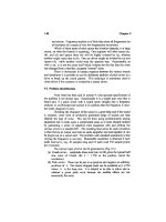
spacing. See Figure 9-9.
Install O-Rings and Back-Up Rings. The oil is pumped between the hub
and shaft through a shallow circular groove machined either in the hub or
in the shaft. Install the O-rings toward this groove, the back-up rings away
from this groove. Do not twist either the O-rings or the back-up rings while
Centrifugal Compressor Rotor Repair 531
Figure 9-9. Methods of determining and limited hub advance on tapered shaft.
installing. After they are installed, look again! The O-rings must be
between the back-up rings and the oil groove! Spread a little bit of thin
oil on the rubber surfaces.
Mount “Other” Components. Read the coupling installation procedure
again. Must other components (such as a sleeve) be mounted on the shaft
before hub? Now is the time to do it.
Mount the Hub on the Shaft. Avoid pinching the O-rings during mounting.
The O-rings will prevent the hub from advancing to the “start” position.
This is acceptable.
Mount the Installation Tool. Wet the threads with thin oil, and rotate the
tool until it butts against the shaft shoulder. The last few turns will require
the use of a spanner wrench.
Connect the Hydraulic Lines. Connect the installation tool to the low pres-
sure oil pump (5,000 psi minimum). Connect the high pressure oil pump
(40,000 psi minimum) to the hole provided either in the center of the shaft
or on the outside diameter of the hub, depending on design. Loosen the
pipe plug of the installation tool and pump all the air out; retighten the
plug. Both pumps must be equipped with pressure gauges. See Figure 9-
10.
Advance the Hub to the Start Position, through pumping the low pressure
oil pump. Continue pumping until the hub advances 0.005 to 0.010 in.
beyond the start position.
532 Machinery Component Maintenance and Repair
Figure 9-10. Hydraulic system for hub installation.
Expand the Hub. Pump the high pressure pump until you read 15,000 to
17,000 psi on the gauge. As the pressure increases, the hub will tend to
move off the shaft. Prevent this movement by occasionally increasing the
pressure at the installation tool.
Check for Oil Leaks. The hub should not be advanced on the shaft if leaks
exist! The pressure at the high pressure oil pump will drop rapidly at first
because the air in the system escapes past the O-rings. Continue pumping
until pressure stabilizes. A pressure loss of no more than 1,000 psi per
minute is acceptable. If the pressure drops faster than that, remove the hub
and replace the O-rings. However, before removing the hub make sure that
the leaks do not occur at the hydraulic connections.
Advance the Hub. Increase the pressure at the installation tool and the hub
will advance on the shaft. If all the previous steps were observed, the
pressure at the high pressure gauge will gradually increase as the hub
advances. If the pressure does not increase, then stop. Remove the hub
and check O-rings. If the pressure increases, keep advancing the hub until
it touches the split collar or until the specified advance is reached. Do not
allow the pressure to exceed 30,000 psi. If it does, open the pressure valve
slowly and release some oil. If in doing this the pressure drops below
25,000 psi, pump the high pressure pump to 25,000 psi, and continue the
hub advance.
Seat the Hub. Very slowly release all the pressure at the high pres-
sure pump. Do not work on that hub for
1
/
2
hour, or one hour in cold
weather. After that, release all the pressure at the installation tool and
remove it.
Verify the Advance. Measure and then record the new overhang of the hub
over the shaft. Subtract from the overhang measured in the start position
and the result must be the specified advance.
Secure the Hub. Remove the split collar from the shaft and install the
retaining nut, but do not overtighten. Secure the nut with the setscrews
provided.
Dismounting of Hydraulically Fitted Hubs
In current practice, when a hydraulically fitted hub is removed, it comes
off the shaft with sudden movement. Lead washers or other damping
means are used to absorb the energy of the moving hub.
Centrifugal Compressor Rotor Repair 533
Koppers Company, Inc., engineers have developed a dismounting
procedure that eliminates the sudden movement of the hub. Without
this sudden movement the dangers related to removing hydraulically fitted
hubs are greatly reduced. However, normal safety procedures should
continue to be used.
Koppers’ dismounting method requires the use of the same tools used
when mounting the hub. The following procedure is recommended:
1. Remove the shaft nut.
2. Mount the installation tool. Wet the shaft threads with thin oil and
rotate the tool until it butts against the shaft shoulder. There should
be a gap between the tool and the hub equal to or larger than the
amount of advance when the hub was installed (check the records).
If the gap is less than required, the wrong installation tool is being
used.
3. Connect the hydraulic lines. Connect the installation tool to the low
pressure oil pump (5,000 psi minimum). Connect the high pressure
oil pump (40,000 psi minimum) to the hole provided either in the
center of the shaft or on the outside diameter of the hub, depending
on the design. Loosen the pipe plug of the installation tool and pump
all air out; retighten the plug. Both pumps must be equipped with
pressure gauges.
4. Activate the installation tool. Pump oil into the installation tool. The
piston will advance until it contacts the hub. Continue pumping until
the pressure is between 100 to 200psi. Check for leaks.
5. Expand the hub. Pump oil between the hub and the shaft by using
the high pressure pump. While pumping watch both pressure gauges.
When the high pressure gauge reads about 20,000 psi the pressure at
the low pressure gauge should start increasing rapidly. This pressure
increase is caused by the force that the hub exerts on the installation
tool, and is an indication that the hub is free to move. Continue
to pump until pressure reaches 25,000 psi. In case the low pressure
at the installation tool does not increase even if the high pres-
sure reaches 30,000 psi, wait for about
1
/
2
hour while maintaining the
pressure. It takes time for the oil to penetrate in the very narrow
space between the hub and the shaft. Do not exceed 30,000 psi.
6. Allow the hub to move. Very slowly open valve at the low pressure
pump. The oil from the installation tool will flow into the pump and
allow the hub to move. The pressure at the high pressure gauge will
also drop. Do not allow it to fall below 5,000psi. If it does, close the
valve and pump more oil at the high pressure pump. Continue the
process until the valve at the low pressure pump is completely open
and the pressure is zero.
534 Machinery Component Maintenance and Repair
7. Remove the hub. Release the high pressure and back off the instal-
lation tool until only two or three threads are still engaged. Pump the
high pressure pump and the hub will slide off the shaft. When the
hub contacts the installation tool, release all the pressure and remove
the tool. The hub should now come off the shaft by hand. Do not
remove the installation tool unless the pressure is zero.
8. Inspect O-rings. Reusing even slightly damaged rings invites trouble.
The safest procedure is to always use new seals and discard the old
ones.
Centrifugal Compressor Rotor Repair 535
Chapter 10
Protecting Machinery Parts
Against Loss of Surface
Many repairs of worn machinery surfaces can be achieved by hard sur-
facing. By definition, hard surfacing is the process of applying, by spe-
cialized welding techniques, a material with properties superior to the
basis metal*.
Perhaps the chief factor limiting wide acceptance of this process today
is the aura of mystery surrounding the properties of the various hard-
surfacing alloys. There are literally hundreds of hard-surfacing alloys
commercially available, each with a strange sounding name and a vendor’s
claim that it is the ultimate material for this or that application. Rather
than sift through the chaff to determine which should be used on an urgent
problem, many machinery maintenance people drop the idea of hard sur-
facing and rely on more familiar techniques. This section will discuss the
various forms of wear, and show how a few hard-surfacing materials can
solve most wear problems. The following information is intended to sim-
plify the field of hard surfacing so that maintenance and design engineers
can effectively use the process to reduce maintenance and fabrication
costs.
Basic Wear Mechanisms
The first step in solving any wear problem is to determine the mode or
modes of wear present
1
. This is of the utmost importance. The same
536
* From “Guide to Hard Surfacing,” by K.G. Budinski, Eastman Kodak Co., in Plant Engi-
neering, 1974. By permission.
Protecting Machinery Parts Against Loss of Surface 537
approach must be taken in new designs, except that then the question to
be asked is not, “How did this part fail?” but “How might wear occur on
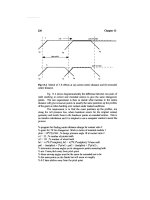
this part?” By way of a quick review, there are four basic types of wear:
adhesive, abrasive, corrosive, and surface fatigue. Each basic type can also
be further categorized, as in Figure 10-1.
Adhesive Wear
The mechanism of adhesive wear is the removal of material from one
or both mating surfaces by the action of particles from one of the surfaces
bonding to the other. With repeated relative motion between the surfaces,
the transferred particles may fracture from the new surface and take
on the form of wear debris. Adhesive wear is thus analogous to friction,
and is present in all sliding systems. It can never be eliminated—only
reduced.
Figure 10-1. Wear mechanisms.
Abrasive Wear
Abrasive wear occurs when hard, sharp particles, or hard, rough sur-
faces, contact soft surfaces and remove material by shearing it from the
softer surface. The amount of metal removed is a function of the nature
of the abrading substance, and of the loading. For this reason, it is common
to subdivide abrasive wear into high stress, low stress, high-velocity
impingement, and filing.
Corrosive Wear
There is no one mechanism to describe corrosive wear. Fretting, the first
form of corrosive wear shown in Figure 10-1, occurs in systems that are
not supposed to move. One of the most common instances of fretting
occurs on shafts, under the press-fitted inner race of a rolling element
bearing. Vibration provides a slight relative motion between the shaft and
the race. This oscillatory motion causes small fragments of one surface to
adhere to the other (adhesive wear), and with repeated vibration or oscil-
lation, the fragments oxidize (corrosive wear) and form abrasive oxides
(abrasive wear) which amplify the surface damage.
Cavitation occurs in highly agitated liquids where turbulence and the
implosion of bubbles cause removal of the protective oxide film on the
metal surface, followed by corrosive attack on the base metal. If the implo-
sion of the bubbles is particularly energetic, as is the case in ultrasonic
devices, the material removal can be quite rapid.
Impingement by high velocity liquids causes removal of protective
oxide films. Metal removal then occurs by corrosion of the active metal
surface.
Erosion involves the same mechanism as impingement. However, the
liquid in this instance contains abrasive particles that enhance the removal
of surface films.
Surface Fatigue
This last form of wear to be discussed results from high compressive
stress because of point or line-contact loading. These high stresses, with
repeated rolling, produce subsurface cracks that eventually propagate and
cause particles to be removed from the surface. Once this occurs, the dete-
rioration of the entire rolling surface starts. This is a result of the addi-
tional compressive stresses that are generated when the first fragments
detached are rerolled into the surface. Surface fatigue of this nature occurs
538 Machinery Component Maintenance and Repair
Protecting Machinery Parts Against Loss of Surface 539
in rolling-element bearings, rails, and other surfaces subjected to point or
line-contact loads.
Hard-Surfacing Techniques
Almost every welding technique can be used to apply a hard-surfacing
material. Referring to the definition of hard-surfacing—applying by
welding or spraying techniques a material with properties superior to those
of the basis metal—it can readily be seen that this can be accomplished
in many ways. Figure 10-2 illustrates most of the methods used. Each has
advantages and disadvantages. Shielded metal-arc welding is the most
common and versatile welding technique, but many of the hard-surfacing
alloys have not been available in a coated electrode form.
Figure 10-2. Hard-surfacing techniques.