ARNOLD, K. (1999). Design of Gas-Handling Systems and Facilities (2nd ed.) Episode 2 Part 1 docx
Bạn đang xem bản rút gọn của tài liệu. Xem và tải ngay bản đầy đủ của tài liệu tại đây (1.24 MB, 25 trang )
236
Design
of
GAS-HANDLING
Systems
and
Facilities
Table
8-4
Properties
of
Solid
Desiccants
Desiccant
Activated
Alumina
Mobil
SOR
Beads
Fluorite
Alumina
Gel
(H-
151)
Silica
Gel
Molecular Sieves (4A)
Bulk
Density
(Jb/fc3)
51
49
50
52
45
45
Specific
Heat
(Btu/ib/*F)
0.24
0.25
0.24
0.24
0.22
0.25
Normal
Sizes
Used
Xi
in.
-8
mesh
4-8
mesh
4-8
mesh
V^/4
inch
4-8
mesh
Vv,
inch
Design
Adsorprive
Capacity
(WT%)
7
6
4-5
7
7
14
Regeneration
Temperature
IT)
3SO
dOO
M)
S(K)
<*»{)+
«0
KM)
<Vl
4*>{»
\X)
Source: API.
desiccants
are
interchangeable
and the
equipment designed
for one
desk-
cant
can
often
be
operated
effectively
with another product. Table
8-4
illustrates
the
most common desiccants used
for gas
dehydration
and
some conservative parameters
to use for
initial design. Desiccant
suppli-
ers' information should
be
consulted
for
detail
design.
All
desiccants exhibit
a
decrease
in
capacity (design loading)
with
increase
in
temperature. Molecular sieves tend
to be the
less
severely
affected
and
aluminas
the
most
affected
by
temperature.
Aluminas
and
molecular sieves
act as a
catalyst with
I-^S
to
form
COS. When
the bed is
regenerated,
sulfur
remains
and
plugs
up the
spaces. Liquid hydrocarbons
also
present
a
plugging problem
to
all
des-
iccants,
but
molecular sieves
are
less susceptible
to
contamination
with
liquid
hydrocarbons.
Silica
gels will shatter
in the
presence
of
free
water
and are
chemically
attacked
by
many
corrosion
inhibitors.
The
chemical
attack permanently
destroys
the
silica gels.
The
other desiccants
are not as
sensitive
to
free
water
and are not
chemically attacked
by
most corrosion inhibitors.
However, unless
the
regeneration temperature
is
high enough
to
desorb
the
inhibitor,
the
inhibitor
may
adhere
to the
desiccants
and
possibly
cause
coking.
The
alumina gels, activated aluminas,
and
molecular sieves
are
all
chemically attacked
by
strong mineral acids
and
their
adsorptive
capacity
Gas
Dehydration
237
will
quickly decline. Special acid
resistant
molecular sieve
desiccants
are
available.
EXAMPLE 8-2:
DRY
DESICCANT
DESIGN
The
detailed design
of
solid
bed
dehydrators
should
be
left
to
experts.
The
general "rules
of
thumb" presented
in
this
chapter
can be
used
for
preliminary
design
as
shown
in the
following example:
Design
Basis
Feed rate
50
MMscfd
Molecular
weight
of gas
17.4
Gas
density
1.701b/ft
3
Operating temperature
110°F
Operating pressure
600
psia
Inlet
dew
point
1
QO°F
(equivalent
to 90
Ib
of
H
2
O/MMcf)
Desired
outlet
dew
point
1
ppm
H
2
O
Water
Adsorbed
For
this
example,
an
8-hour
on-stream
cycle with
6
hours
of
regenera-
tion
and
cooling will
be
assumed.
On
this basis,
the
amount
of
water
to
be
adsorbed
per
cycle
is:
8/24
x 50
MMcf
x 90
Ib/MMcf
=
1,500
Ib
H
2
O/cycle
Loading
Because
of the
relative cost,
use
Sorbeads
as the
desiccant
and
design
on
the
basis
of 6%
loading.
Sorbeads
weigh approximately
49
lb/ft
3
(bulk
density).
The
required weight
and
volume
of
desiccant
per bed
would
be:
238
Design
of
GAS-HANDLING
Systems
and
Facilities
Tower
Sizing
Recommended maximum superficial velocity
at 600
psia
is
about
55
ft/min.
From
Equation 8-2, assuming
Z
=
1.0:
The
pressure drop
from
Equation 8-3, assuming
]
A-w.
bead
and
ji
=
0.01
cp, is:
The bed
height
is:
This
is
higher
than
the
recommended
8
psi. Choose
a
diameter
of 5 ft 6
in.
Leaving
6 ft
above
and
below
the
bed,
the
total tower length including
space
to
remove
the
desiccant
and
refill would
be
about
28 ft.
This yields
an
L/D
of
28/5.5
=
5.0.
Regeneration
Heat
Requirement
Assume
the bed
(and tower)
is
heated
to
350°F.
The
average tempera-
ture
will
be
(350
+
110)°F/2
=
230°F.
The
approximate weight
of
the
5 ft
6 in. ID x 28 ft x 700
psig tower
is
53,000
Ib
including
the
shell, heads,
nozzles
and
supports
for the
desiccant.
The
heating
and
cooling requirement
can be
calculated using
Gas
Dehydration
239
Heating
Requirement/Cycle
*Specific
heat
of
steel.
**The
number
"1100
Btu/lb"
is the
heat
of
water desorption,
a
value
supplied
by the
desiccant
manufacturer,
***The
majority
of the
water will desorb
at the
average temperature. This heat require-
ment
represents
the
sensible heat
required
to
raise
the
temperature
of
the
water
to the
desorption
temperature.
Cooling
Requirement/Cycle
These
methods
for
calculating
the
heating
and
cooling requirements
are
conservative
estimates
assuming that
the
insulation
is on the
outside
of
the
towers.
The
requirements
will
be
less
if the
towers
are
insulated
internally.
Regeneration
Gas
Heater
Assume
the
inlet temperature
of
regeneration
gas is
4QO°F.
In the
beginning
the
initial outlet temperature
of the bed
will
be the bed
temper-
ature
of
110°F;
at the end of the
heating cycle,
the
outlet temperature will
be
the
design value
of
350°F.
So the
average outlet temperature
is
(350
+
110)/2
or
230°F, Then
the
volume
of gas
required
for
heating
will
be
240
Design
of
GAS-HANDLING
Systems
and
Facilities
The
regeneration
gas
heater
load
Q
H
is
then:
For
design,
add 25% for
heat
losses
and
non-uniform
flow.
Assuming
a
3-hour
heating cycle,
the
regenerator
gas
heater
must
be
sized
for
Regeneration
Gas
Cooler
The
regeneration
gas
cooling load
is
calculated using
the
assumption
that
all of the
desorbed water
is
condensed during
a
half hour
of the
3-hour
cycle.
The
regeneration
gas
cooler load
Q
c
would
be:
Cooling
Cycle
For the
cooling cycle
the
initial outlet temperature
is
350°F
and
at the
end
of the
cooling
cycle,
it is
approximately
110°F.
So the
average
outlet
temperature
is
(350
+
110)72
=
230°F. Assuming
the
cooling
gas is at
110°F,
the
volume
of gas
required
for
cooling will
be
*
Steam
tables.
**
Specific
heat
of gas at the
average temperature.
CHAPTER
9
Gas
Processing*
The
term
"gas
processing"
is
used
to
refer
to the
removing
of
ethane,
propane, butane,
and
heavier components
from
a gas
stream. They
may
be
fractionated
and
sold
as
"pure"
components,
or
they
may
be
combined
and
sold
as a
natural
gas
liquids mix,
or
NGL.
The
first step
in a gas
processing plant
is to
separate
the
components
that
are to be
recovered
from
the gas
into
an NGL
stream.
It may
then
be
desirable
to
fractionate
the NGL
stream into various liquefied petroleum
gas
(LPG) components
of
ethane, propane, iso-butane,
or
normal-butane.
The LPG
products
are
defined
by
their vapor pressure
and
must meet cer-
tain
criteria
as
shown
in
Table
9-1.
The
unfractionated natural
gas
liquids
product (NGL)
is
defined
by the
properties
in
Table
9-2.
NGL is
made
up
principally
of
pentanes
and
heavier hydrocarbons although
it may
con-
tain
some butanes
and
very small amounts
of
propane.
It
cannot contain
heavy
components that
boil
at
more than
375°F.
In
most instances
gas
processing plants
are
installed because
it is
more
economical
to
extract
and
sell
the
liquid products even though
this
low-
ers the
heating value
of
gas.
The
value
of the
increased volume
of
liquids
sales
may be
significantly higher than
the
loss
in gas
sales revenue
because
of a
decrease
in
heating value
of the
gas.
*Reviewed
for the
1999
edition
by
Douglas
L.
Erwin
of
Paragon Engineering
Services,
Inc.
241
Product
Designation
Product
Characteristics
Composition
Vapor
pressure
at
100°F,*
psig, max.
Volatile
residue:
temperature
at 95%
evaporation.
deg.
F,
max.
or
butane
and
heavier,
liquid
volume
percent max.
pentane
and
heavier,
liquid
volume
percent max.
Residual
matter:
residue
on
evaporation
of
100
ml,
max.
oil
stain
observation
Corrosion, copper strip, max.
Total
sulfur,
ppmw
Moisture
content
Free water content
Commercial
Propane
Predominantly
propane
and/or
propylene.
208*
-37*
2.5
—
0.05ml
pass
(1)
No, 1
185
pass
_
Commercial
Butane
Predominantly
butanes
and/or
butylenes.
70*
36*
—
2.0
—
—
No. 1
140
_
none
Commercial
B-P
Mixtures
Predominantly
mixtures
of
butanes
and/or
butylenes
with propane
and/or
propylene.
208*
36*
—
2.0
—
—
No. 1
140
—
none
Propane
HD-5
Not
less
than
90
liquid
volume
percent
propane;
not
more
than
5
liquid volume
percent propylene.
208*
-37*
2,5
—
0.05ml
pass
(1)
No.
1
123
pass
_.
Test
Methods
ASTMD-2
163-82
ASTMD-
1267-84
ASTMD-
1837-81
ASTMD-2
163-82
ASTM
D-2
163-82
ASTMD-2
158-80
ASTM
D-21
58-80
ASTMD-
1838-84
ASTM
D-2784-80I
GPA
Propane
Dryness
Test
(Cobalt Bromide)
or
D-27
13-81
—
Table
9-1
GPA
Liquefied
Petroleum
Gas
Specifications
(from
GPA
Standard
2140-86)
(I)
An
acceptable
product
shall
not
-field
a
persistent
oil
ring
when
0.3 ml
of
solvent
residue mixture
is
added
to a
filter
paper
in
(l-1
itu'remento
ana
examined
in
davlixht
after
2
minutes
ax
described
in
ASTM
D-2158.
*Metric
Equivalents
208psig
=
1434
kPa
gauge
70psig
= 483
kPa
gauge
-
37"F
=
-38J
C
C
36*F
-
2.2*C
KXrF
=
37.8
S
C
Courtesy:
Gas
Processing
Suppliers
Association,
Tenth
Edilion,
Engineering
Data Book
Gas
Processing
243
Table
9-2
GPA
Natural
Gasoline
Specifications
Product
Characteristic
Reid
Vapor
Pressure
Percentage
evaporated
at
140°F
Percentage
evaporated
at
275
°F
End
point
Corrosion
Color
Reactive
Sulfur
Specification
10-34
pounds
25-85
Not
less
than
90
Not
more than
375°F
Not
more
than
classification
1
Not
less than plus
25
(Saybolt)
Negative,
"sweet"
Test
Method
ASTM
D-323
ASTMD-2J6
ASTMD-216
ASTMD-216
ASTM
D-
130
(modified)
ASTM
D-
156
GPA
11
38
In
addition
to the
above general specifications, natural gasoline shall
be
divided
into
24
possible grades
on the
basis
of
Reid vapor pressure
and
percentage
evaporated
at
140°F.
Each grade
shall
have
a
range
in
vapor pressure
of
four
pounds,
and a
range
in the
percentage evaporated
at
140°F
of
15%.
The
maximum
Reid vapor pressure
of the
various grades shall
be
14,18,
22, 26, 30,
and
34
pounds respectively.
The
minimum percentage evaporated
at
140°F
shall
be
25, 40, 55, and 70
respectively. Each grade
shall
be
designated
by its
maximum
vapor pressure
and its
minimum percentage evaporated
at
140°F,
as
shown
in the
following:
Grades
of
Natural
Gasoline
Percentage
Evaporated
at
140°F
Reid
Vapor Pressure
34
30
26
22
18
14
10
25
!
Grade 34-25
Grade 30-25
Grade 26-25
Grade 22-25
Grade
18-25
Grade 14-25
40
i
Grade
34-40
Grade
30-40
Grade 26-40
Grade
22-40
Grade 18-40
Grade 14-40
55
i
Grade 34-55
Grade 30-55
Grade
26-55
Grade 22-55
Grade 18-55
Grade
14-55
70 85
i
i
Grade
34-70
Grade 30-70
Grade 26-70
Grade 22-70
Grade
18-70
Grade
14-70
""Courtesy:
Gas
Processing Suppliers
Association,
Tenth Edition,
Engineering
Data
Book
244
Design
of
GAS-HANDLING
Systems
and
Facilities
In
deciding whether
it is
economical
to
remove liquids
from
a
natural
gas
stream,
it is
necessary
to
evaluate
the
decrease
in gas
value
after
extraction
of the
liquid. Table
9-3
shows
the
break-even value
for
various
liquids.
Below these
values
the
molecules will
be
more valuable
as
gas.
The
difference
between
the
actual
sales
price
of the
liquid
and the
break-even
price
of the
liquid
in
Table
9-3
provides
the
income
to pay out
the
capital cost,
fuel
cost,
and
other operating
and
maintenance expenses
necessary
to
make
the
recovery
of the gas
economically
attractive.
Another
objective
of gas
processing
is to
lower
the Btu
content
of the
gas by
extracting heavier components
to
meet
a
maximum allowable
heating
limit
set by a gas
sales contract.
If the gas is too rich in
heavier
components,
the gas
will
not
work properly
in
burners that
are
designed
for
lower
heating values.
A
common maximum limit
is
1100
Btu per
SCE
Thus,
if the gas is rich in
propane
and
heavier components
it may
have
to be
processed
to
lower
the
heating value, even
in
cases
where
it
may
not be
economical
to do so.
This chapter briefly describes
the
basic processes used
to
separate
LPG and NGL
liquids
from
the gas and to
fractionate them into their var-
ious
components.
It is
beyond
the
scope
of
this text
to
discuss detailed
design
of gas
processing plants.
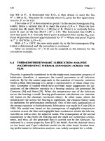
ABSORPTION/LEAN
OIL
The
oldest kind
of gas
plants
are
absorption/lean
oil
plants, where
a
kerosene type
oil is
circulated through
the
plant
as
shown
in
Figure
9-1.
The
"lean
oil"
is
used
to
absorb light hydrocarbon components
from
the
gas.
The
light components
are
separated
from
the
rich
oil and the
lean
oil
is
recycled.
Typically
the
inlet
gas is
cooled
by a
heat exchanger with
the
outlet
gas
and a
cooler before entering
the
absorber.
The
absorber
is a
contact
tower, similar
in
design
to the
glycol contact tower explained
in
Chapter
8.
The
lean
absorber
oil
trickles
down over trays
or
packing while
the gas
flows
upward
countercurrent
to the
absorber
oil.
The gas
leaves
the top
of
the
absorber while
the
absorber
oil,
now rich in
light hydrocarbons
from
the
gas,
leaves
the
bottom
of the
absorber.
The
cooler
the
inlet
gas
stream
the
higher
the
percentage
of
hydrocarbons which will
be
removed
by
the
oil.
Rich
oil flows to the rich oil
de-ethanizer
(or
de-methanizer)
to
reject
the
methane
and
ethane
(or the
methane alone)
as flash
gas.
In
most
lean
Gas
Processing
245
Figure
9-1.
Simplified
flow
diagram
of an
absorption
plant.
oil
plants
the ROD
unit
rejects both methane
and
ethane since very little
ethane
is
recovered
by the
lean oil.
If
only methane were rejected
in the
ROD
unit, then
it may be
necessary
to
install
a
de-ethanizer column
downstream
of the
still
to
make
a
separate ethane product
and
keep
ethane
from
contaminating (i.e., increasing
the
vapor
pressure
of) the
other liquid products made
by the
plant.
The ROD is
similar
to a
cold
feed
stabilizing tower
for the
rich oil.
Heat
is
added
at the
bottom
to
drive
off
almost
all the
methane (and most
likely ethane)
from
the
bottoms product
by
exchanging heat with
the hot
lean
oil
coming
from
the
still.
A
reflux
is
provided
by a
small stream
of
cold
lean
oil
injected
at the top of the
ROD.
Gas off the
tower overhead
is
used
as
plant
fuel
and/or
is
compressed.
The
amount
of
intermediate
components flashed with this
gas can be
controlled
by
adjusting
the
cold
lean
oil
reflux
rate.
Absorber
oil
then
flows to a
still
where
it is
heated
to a
high enough
temperature
to
drive
the
propanes, butanes,
pentanes
and
other natural
gas
liquid components
to the
overhead.
The
still
is
similar
to a
crude
oil
stabilizer
with
reflux.
The
closer
the
bottom temperature
approaches
the
boiling
temperature
of the
lean
oil the
purer
the
lean
oil
which
will
be
recirculated
to the
absorber. Temperature control
on the
condenser keeps
lean
oil
from
being lost with
the
overhead.
246
Design
of
GAS-HANDLING
Systems
and
Facilities
Thus
the
lean
oil,
in
completing
a
cycle, goes through
a
recovery stage
where
it
recovers
light
and
intermediate
components from
the
gas,
a
rejec-
tion
stage where
the
light ends
are
eliminated
from
the rich oil and a
sepa-
ration
stage where
the
natural
gas
liquids
are
separated
from
the rich
oil.
These plants
are not as
popular
as
they
once were
and are
rarely,
if
ever,
constructed anymore. They
are
very
difficult
to
operate,
and it Is
difficult
to
predict their
efficiency
at
removing liquids
from
the gas as the
lean
oil
deteriorates with time. Typical
liquid
recovery levels are:
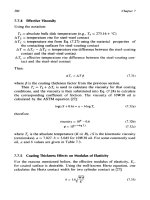
REFRIGERATION
In
a
refrigeration plant
the
inlet
gas is
cooled
to a low
enough tempera-
ture
to
condense
the
desired fraction
of LPG and
NGL.
Either
freon
or
propane
is
used
as the
refrigerant. Figure
9-2
shows
a
typical
refrigera-
tion plant.
The free
water must
be
separated
and the dew
point
of the gas
lowered
before
cooling
the
feed
to
keep hydrates from forming.
It is
possible
to
Figure
9*2. Simplified
flow
diagram
of a
refrigeration plant.
Gas
Processing
247
dehydrate
the gas
with
TEG or
mole sieves
to the
required
dew
point.
It
is
more common
to
lower
the
hydrate temperature
by
injecting
glycol
in
the gas
after
separation
of
free
water.
The
glycol
and
water separate
in
the
cold separator where they
are
routed
to a
regenerator,
the
water
is
boiled
off and the
glycol
is
circulated back
to be
injected into
the
inlet
stream.
Some glycol will
be
lost
with
time
and
will have
to be
made
up,
The
most common glycol used
for
this service
is
ethylene
glycol
because
of
its low
cost
and the
fact
that
at the
low
temperatures
it is not
lost
to the
gas
phase.
The
chiller
is
usually
a
kettle type exchanger. Freon (which
is
cooled
in
a
refrigeration cycle
to
-20°F)
is
able
to
cool
the gas to
approximately
-15°F.
Propane, which
can be
cooled
to
~40°F,
is
sometimes used
if
lower
gas
temperatures
and
greater recovery
efficiences
are
desired.
The gas and
liquid
are
separated
in the
cold separator, which
is a
three-
phase
separator. Water
and
glycol come
off the
bottom, hydrocarbon
liq-
uids
are
routed
to the
distillation tower
and gas flows out the
top.
If it is
desirable
to
recover ethane, this still
is
called
a
de-methanizer.
If
only
propane
and
heavier components
are to be
recovered
it is
called
a
de-etha-
nizer.
The gas is
called "plant residue"
and is the
outlet
gas
from
the
plant.
The
tower operates
in the
same manner
as a
condensate stabilizer
with
reflux.
The
inlet liquid stream
is
heated
by
exchange with
the gas to
approximately
30°F
and is
injected
in the
tower
at
about
the
point
in
the
tower
where
the
temperature
is
30°F.
By
adjusting
the
pressure,
number
of
trays,
and the
amount
of
reboiler
duty,
the
composition
of the
bottoms
liquid
can be
determined.
By
decreasing
the
pressure
and
increasing
the
bottoms temperature
more
methane
and
ethane
can be
boiled
off the
bottoms liquid
and the
RVP
of the
liquid stream decreased
to
meet requirements
for
sales
or
fur-
ther
processing. Typical liquid recovery levels
are:
These
are
higher than
for a
lean
oil
plant.
It is
possible
to
recover
a
small
percentage
of
ethane
in a
refrigeration plant.
This
is
limited
by the
ability
to
cool
the
inlet stream
to no
lower than
-40°F
with
normal
refrigerants.
248
Design
of
GAS-HANDLING
Systems
and
Facilities
Most refrigeration plants
use
freon
as the
refrigerant
and
limit
the
low-
est
temperature
to
~20°F. This
is
because
the
ANSI piping codes
require
special
metallurgy
considerations below
-20°F
to
assure
ductility.
Cryogenic
Plants
Figure
9-3
shows
a
typical cryogenic plant where
the gas is
cooled
to
-100°F
to
~150°F
by
expansion through
a
turbine
or
Joule-Thompson
(J-T)
valve.
In
this example liquids
are
separated
from
the
inlet
gas at
100°F
and
1,000 psig.
It is
then dehydrated
to
less
than
1 ppm
water
vapor
to
assure that hydrates
will
not
form
at the low
temperatures
encountered
in the
plant.
Typically,
a
rnole
sieve
dehydrator
is
used.
The gas is
routed through
heat
exchangers where
it is
cooled
by the
residue
gas,
and
condensed liquids
are
recovered
in a
cold separator
at
approximately
-90°F.
These liquids
are
injected into
the
de-methanizer
at
a
level
where
the
temperature
is
approximately
-90°F.
The gas is
then
expanded (its
pressure
is
decreased
from inlet
pressure
to 225
psig)
through
an
expansion valve
or a
turboexpander.
The
turboexpander uses
the
energy removed
from
the gas due to the
pressure drop
to
drive
a
com-
pressor, which helps
recompress
the gas to
sales pressure.
The
cold
gas
{-150°F)
then enters
the
de-methanizer column
at a
pressure
and
temper-
ature
condition where most
of the
ethanes-plus
are in the
liquid
state.
Figure
9-3.
Simplified
flow
diagram
of a
cryogenic
plant.
Gas
Processing
249
The
de-methanizer
is
analogous
to a
cold feed
condensate
stabilizer.
As
the
liquid
falls
and is
heated,
the
methane
is
boiled
off and the
liquid
becomes leaner
and
leaner
in
methane. Heat
is
added
to the
bottom
of the
tower
using
the hot
discharge residue
gas
from
the
compressors
to
assure
that
the
bottom liquids have
an
acceptable
RVP or
methane content,
The
gas
turbine driven compressor
is
required since there
are
energy
losses
in the
system.
The
energy generated
by
expanding
the gas
from
600
psig
to 225
psig
in the
turbo-expander cannot
be
100% recovered
and
used
to
recompress
the
residue
gas
from
225
psig
to 600
psig.
In
this
particular
plant
it is
only capable
of
recompressing
the gas to 400
psig,
Thus, even
if the
inlet
gas and
sales
gas
were
at the
same pressure,
it
would
be
necessary
to
provide some energy
in the
form
of a
compressor
to
recompress
the
gas.
Because
of the
lower temperatures that
are
possible, cryogenic
plants
have
the
highest liquid recovery levels
of the
plants
discussed.
Typical
levels
are:
C
2
>
60%
C
3
> 90%
C
4+
=
100%
CHOICE
OF
PROCESS
Because
of the
greater
liquid recoveries, cryogenic plants
are the
most
common designs currently being installed. They
are
simple
to
operate
and
easy
to
package, although somewhat more expensive than refrigera-
tion
plants. Refrigeration plants
may be
economical
for rich gas
streams
where
it is not
desired
to
recover ethane. Lean
oil
plants
are
expensive
and
hard
to
operate. They
are
rarely designed
as new
plants anymore.
Existing lean
oil
plants
are
sometimes salvaged, refurbished
and
moved
to
new
locations.
Fractionation
The
bottoms liquid
from
any gas
plant
may be
sold
as a
mixed prod-
uct.
This
is
common
for
small, isolated plants where there
is
insufficient
local demand.
The
mixed product
is
transported
by
truck, rail, barge
or
pipeline
to a
central location
for
further processing.
Often
it is
more eco-
nomical
to
separate
the
liquid into
its
various components
and
sell
it as
250
Design
of
GAS-HANDLING
Systems
and
Facilities
Figure
9-4.
Simplified
flow
diagram
of a
fractionation
plant.
ethane, propane, butane,
and
natural gasoline.
The
process
of
separating
the
liquids into these components
is
called fractionation.
Figure
9-4
shows
a
typical fractionation system
for a
refrigeration
or
lean
oil
plant.
The
liquid
is
cascaded through
a
series
of
distillation tow-
ers
where successively heavier
and
heavier components (fractions)
are
separated
as
overhead
gas.
In
this figure
the
liquid
from
the
still
of an
absorption plant
or the
de-methanizer
(or
de-ethanizer) tower
of an
expansion
or
refrigeration plant
is
routed
to a
de-propanizer.
If
there
is
too
high
a
fraction
of
butanes-plus
in the
propane, this
can be
reduced
by
adjusting
the
de-propanizer pressure upward
or
reflux
condensing tem-
perature downward.
If the
vapor pressure
of the
propane exceeds
the
required specification this means that
the
fraction
of
methane
and
ethane
in
the
inlet stream
is too
high. This fraction
can be
adjusted downward
by
increasing
the
temperature
or
decreasing
the
operating pressure
of the
still
or
tower that feeds liquid
to the
de-propanizer.
The
de-butanizer
works
in a
similar manner.
The
upstream tower (de-
propanizer)
determines
the
maximum vapor
pressure
of the
butane prod-
uct.
If the
concentration
of
propane-minus
is too
large
in the
inlet stream,
the
vapor pressure
of the
butane overheads will
be too
high. Similarly,
the
concentration
of
pentanes-plus
in the
butane will depend upon
the
Gas
Processing
251
reflux
condensing temperature
and
tower operating
pressure.
If the
pen-
tanes-plus
exceed specifications,
further
reflux
cooling
or a
higher oper-
ating
pressure will
be
needed
to
condense
pentanes-plus
from
the
butane
overheads.
The
temperature
at the
base
of the
de-butanizer
determines
the
vapor
pressure
of the
gasoline product.
If its
vapor pressure
is too
high,
the
temperature must
be
increased
or the
tower pressure decreased
to
drive
more butanes-minus
out of the
bottoms liquids.
If
the
feed
to the
fractionator contains recoverable ethane, such
as is
likely
to be the
case with
a
cryogenic plant, then
a
de-ethanizer
tower
would
be
installed upstream
of the
de-propanizer.
Design
Considerations
The
design
of any of the
distillation
processes
discussed requires
choosing
an
operating pressure, bottoms temperature,
reflux
condenser
temperature
and
number
of
trays. This
is
normally done using
any one of
several
commercially available process simulation programs which
can
perform
the
iterative
calculations
discussed
in
Chapter
6.
Some typical parameters
for
design
are
shown
in
Table 9-4.
The
actual
•
optimum
to use for any
given process will vary depending
on
actual
feed
properties, product specifications, etc.
In
Table
9-4 the
actual number
of
trays
are
included. This
is
because
complete
equilibrium between vapor
and
liquid
is
normally
not
reached
on
each tray.
For
calculation purposes
the
number
of
theoretical flashes
may
be
quite
a bit
less than
the
number
of
trays.
For
smaller diameter
Table
9-3
Gas
Caloric Heating
Cost
Basis
Evaluation
for
Liquids
Recovery
Assumed
Value
of Gas
>»
Gas
Component
Ethane
Propane
Butane
Pentane
Net
Heating
Value
Btu/SCF
1618
2316
3010
3708
SCF/Gallon
37.5
36.4
31.8
27.7
52.00/MMBtu
Equivalent
Value
$/Gallon
0.1213
0.1686
0.1915
0.2054
$3.00/MMBtu
Equivalent
Value
$/Gallon
0.1820
0.2529
0.2872
0.3081
252
Design
of
GAS-HANDLING
Systems
and
Facilities
Table
9-4
Typical
Fractionator-Absorber/Slripper
Design
Number
of
Trays
Approximate
Ranges
Shown
Tower
Lean
Oil
Plant
Absorber
Rich
Oil
De-methanizer
Rich
Oil
De-ethanizer
Rich
Oil
Still
Refrigeration Plant
De-methanizer
De-ethanizer
De-propanizer
De-butanizer
Pressure
Range
psig
200-1100
450-600
175-300
85-160
550-650
350-500
200-300
70-100
Actual
Trays
Above
Main
Feed
Number
24-30
20-30
24-30
1
2-60
14-30
10-70
17-70
18-70
Actual
Trays
Below
Main
Feed
Number
20-50
20-50
20-50
16-60
26-30
20-70
18-70
15-70
towers
packing
is
used instead
of
trays. Manufacturers supply data
for
their
packing
material
which indicates
the
amount
of
feet
of
packing
required
to
provide
the
same mass transfer
as a
standard bubble
cap
tray,
Some recent advances
in
structured packing
are
being used
by
some
operators
in
larger diameter towers where they would have
normally
used
trays.
The
structured packing
is
said
to
allow both smaller diameter
and
less height
of
tower.
Once
the
operating conditions
are
established
for a
tower,
its
diameter
and
height
can be
chosen
using data
available
from
tray
and
packing
manufacturers.
The
details
of
tower diameter
selection,
tray spacing,
and
internal
design
are
beyond
the
scope
of
this
text.
CHAPTER
10
Compressors
*
Compressors
are
used whenever
it is
necessary
to
flow
gas
from
a
lower pressure
to a
higher pressure system. Flash
gas
from
low-pressure
vessels used
for
multistage stabilization
of
liquids,
oil
treating, water
treating,
etc.,
often
exists
at too low a
pressure
to flow
into
the gas
sales
pipeline. Sometimes this
gas is
used
as
fuel
and the
remainder
flared
or
vented.
Often
it is
more
economical
or it is
necessary
for
environmental
reasons
to
compress
the gas for
sales.
In a gas
field,
a
compressor used
in
this
service
is
normally called
a
"flash
gas
compressor."
Flash
gas
com-
pressors
are
normally characterized
by low
throughput rate
and
high
dif-
ferential
pressure.
The
differential
pressure
is
expressed
in
terms
of
overall compressor
ratio,
R
T
,
which
is
defined
as:
where
R
T
=
overall
compressor ratio
P
d
=
discharge pressure, psia
P
s
=
suction pressure, psia
Flash
gas
compressors typically have
an
overall compressor ratio
in the
range
of 5 to 20.
*
Reviewed
for the
1999
edition
by
John
H.
Galey
of
Paragon Engineering Services,
Inc,
253
254
Design
of
GAS-HANDLING
Systems
and
Facilities
In
some marginal
gas
fields,
and in
many larger
gas
fields that experi-
ence
a
decline
in flowing
pressure with time,
it may be
economical
to
allow
the
wells
to flow at
surface
pressures below that required
for gas
sales.
In
such cases
a
"booster
compressor"
may be
installed. Booster
compressors
are
typically characterized
by low
overall compressor
ratio
(on
the
order
of 2 to
5)
and
relatively high throughput.
Booster compressors
are
also used
on
long pipelines
to
restore pres-
sure
drop lost
to
friction.
The
design
of a
long pipeline requires trade-off
studies
between
the
size
and
distance between
booster
compressor
sta-
tions
and
the
diameter
and
operating pressure
of the
line.
The use of
large compressors
is
probably more prevalent
in oil
field
facilities
than
in gas field
facilities.
Oil
wells
often
require
low
surface
pressure
and the gas
that
flashes off the oil in the
separator must
be
com-
pressed
in a flash gas
compressor.
Often
a gas
lift
system
is
needed
to
help
lift
the oil to the
surface.
As
described
in
Volume
1,
a
"gas
lift
com-
pressor" must compress
not
only
the
formation
gas
that
is
produced
with
the
oil,
but
also
the
gas-lift
gas
that
is
recirculated down
the
well.
Gas
lift
compressors
are
characterized
by
both
high
overall compressor ratios
and
relatively
high throughputs.
Often,
other
forms
of
artificial
lift
are
used
to
produce
oil
wells such
as
downhole
submersible pumps
and rod
pumps that require that most
of
the
formation
gas be
separated downhole
and flowed up the
annul
us
.
between
the
tubing
and the
casing. When
it is
economical
to
recover this
gas,
or
when
the gas
must
be
recovered
for
environmental reasons,
a
"casinghead
gas
compressor" will
be
installed.
These
are
sometimes
called "casing vapor recovery (CVR) units"
or
just "vapor recovery units
(VRU)."
Casinghead compressors
are
typically characterized
by low
suc-
tion
pressure
(0 to 25
psig). They
often
discharge
at low
pressure
(50 to
300
psig) into
the
suction
of a
booster
or flash gas
compressor
or
into
a
low-pressure
gas
gathering system that gathers
gas
from
several locations
to
a
central
compressor
station.
Vapors
from
tanks
and
other atmospheric equipment
may be
recovered
in
a
"vapor recovery
compressor"
(VRU). Vapor recovery compressors
have
very
low
suction
pressure
(0 to 8
ounces gauge)
and
typically have
low
flow
rates. They normally discharge into
the
suction
of a flash gas
compressor.
This chapter presents
an
overview
of the
types
of
compressors,
consid-
erations
for
selecting
a
type
of
compressor,
a
procedure
for
estimating
horsepower
and
number
of
stages,
and
some
process
considerations
for
both
reciprocating
and
centrifugal compressors. Chapter
11
discusses
Compressors
255
reciprocating
compressors
in
more detail,
as
this
Is the
most common
type
used
in oil and gas
field
compression.
TYPES
OF
COMPRESSORS
Volume
1
explains that pumps
can be
classified
as
either positive-dis-
placement
or
kinetic.
The
same
is
true
for
compressors.
In a
positive
dis-
placement compressor
the gas is
transported
from
low
pressure
to
high
pressure
in a
device that reduces
its
volume
and
thus increases
its
pres-
sure.
The
most common type
of
positive displacement
compressors
are
reciprocating
and
rotary (screw
or
vane) just
as was the
case
for
pumps.
Kinetic
compressors
impart
a
velocity head
to the
gas,
which
is
then
con-
verted
to a
pressure head
in
accordance with Bernoulli's
Law
as the gas
is
slowed down
to the
velocity
in the
discharge line. Just
as was the
case
with
pumps, centrifugal compressors
are the
only form
of
kinetic
com-
pressor commonly used,
Reciprocating
Compressors
A
reciprocating
compressor
is a
positive-displacement
machine
in
which
the
compressing
and
displacing element
is a
piston moving linear-
ly
within
a
cylinder. Figure
10-1
shows
the
action
of a
reciprocating
compressor.
In
Position
1
the
piston
is
moving away
from
the
cylinder head
and
the
suction
valve
is
open, allowing
the
cylinder pressure
to
equal suction
pressure
and gas to
enter
the
cylinder.
The
discharge valve
is
closed.
At
Position
2 the
piston
has
traveled
the
full
stroke within
the
cylinder
and
the
cylinder
is
full
of gas at
suction pressure.
The
piston begins
to
move
to
the
left,
closing
the
suction valve.
In
moving from
Position
2 to
Posi-
tion
3, the
piston moves toward
the
cylinder head
and the
volume
is
reduced. This increases pressure until
the
cylinder pressure
is
equal
to the
discharge
pressure
and the
discharge
valve
opens.
The
piston
continues
to
move
to the end of the
stroke near
the
cylinder head, discharging
gas.
Pressure
in the
cylinder
is
equal
to
discharge
pressure from Position
3 to
Position
4. As the
piston reverses
its
travel
the gas
remaining within
the
cylinder
expands until
it
equals suction pressure
and the
piston
is
again
in
Position
1.
Reciprocating compressors
are
classified
as
either "high
speed"
or
"slow
speed."
Typically, high-speed compressors
run at a
speed
of 900 to
J
200
rpm
and
slow-speed
units
at
speeds
of 200 to 600
rpm.
256
Design
of
GAS-HANDLING
Systems
and
Facilities
Figure
10-1.
Reciprocating
compressor
action.
Figure
10-2
shows
a
high-speed compressor
frame and
cylinders.
The
upper
compressor
is
called
a two
throw machine because
it has two
cylin-
ders attached
to the frame and
running
off the
crank
shaft.
The
lower com-
pressor
is a
four-throw machine
because
it has
four
cylinders
attached
to
the
frame.
The
number
of
"throws" refers
to the
number
of
pistons.
As
pointed
out in
Volume
1,
Chapter
3, a
compressor
may
have
any
number
of
stages. Each stage normally contains
a
suction scrubber
to
separate
any
liquids that carry over
or
condense
in the gas
line prior
to
the
compressor cylinder
(or
case
for
centrifugal compressors). When
gas
Compressors
257
Figure
10-2.
High-speed
reciprocating
compressor
frames and
cylinders.
(Courtesy
or
Dresser-Kara?
Company.)
is
compressed,
its
temperature increases. Therefore,
after
passing through
the
cylinder
the gas is
usually cooled before being routed
to
another suc-
tion
scrubber
for
another
stage
of
compression.
A
stage
of
compression
thus
consists
of a
scrubber, cylinder,
and
after-cooler. (The discharge
from
the
final
cylinder
may not be
routed
to an
after-cooler.)
258
Design
of
GAS-HANDLING
Systems
and
Facilities
The
number
of
throws
is not the
same
as the
number
of
stages
of
com-
pression.
It is
possible
to
have
a
two-stage, four-throw compressor.
In
this
case there would
be two
sets
of two
cylinders working
in
parallel.
Each
set
would have
a
common suction
and
discharge.
High-speed units
are
normally
"separable."
That
is, the
compressor
frame
and
driver
are
separated
by a
coupling
or
gear box. This
is
opposed
to
an
"integral" unit where power cylinders
are
mounted
on the
same
frame
as the
compressor cylinders,
and the
power pistons
are
attached
to
the
same drive
shaft
as the
compressor cylinders.
High-speed units
are
typically engine
or
electric
motor driven,
although
turbine drivers have also been used. Engines
or
turbines
can be
either
natural
gas or
diesel
fueled.
By far the
most common driver
for a
high-speed compressor
is a
natural
gas
driven engine.
Figure
10-3
shows
a
high-speed engine-driven compressor package.
The
unit typically comes complete
on one
skid with driver, compressor,
suction scrubbers
and
discharge coolers
for
each stage
of
compression
and
all
necessary piping
and
controls.
On
large units
(>
1,000
hp
plus)
the
cooler
may be
shipped
on a
separate skid.
The
major
characteristics
of
high-speed reciprocating compressors are;
Size
•
Numerous sizes from
50 hp to
3000
hp.
•
2, 4, or 6
compressor cylinders
are
common.
Ady_antages
•
Can be
skid mounted.
«
Self-contained
for
easy installation
and
easily moved.
• Low
cost
compared
to
low-speed
reciprocating units.
»Easily
piped
for
multistage compression.
•
Size suitable
for
field gathering offshore
and
onshore.
•
Flexible capacity limits.
• Low
initial cost.
Disadvantages
•
High-speed engines
are not as
fuel
efficient
as
integral engines
(7,500
to
9,000
Btu/bhp-hr).
Compressors
259
Figure
10-3.
High-speed
reciprocating
compressor
packages.
(Courtesy
of
Dresser-
Rand
Company.}
•
Medium range compressor
efficiency
(higher than centrifugal;
lower
than
low-speed).
•
Short
life
compared
to
low-speed.
•
Higher maintenance cost than low-speed
or
centrifugal.
Low-speed units
are
typically integral
in
design
as
shown
in
Figure
10-4.
"Integral" means that
the
power cylinders that turn
the
crank
shaft
are in the
same case (same housing)
as the
cylinders that
do the
com-
pressing
of the
gas.
There
is one
crank
shaft.
Typically, integrals
are
con-
Figure
10-4.
Sectional
view
of
integral engine compressor.
(Courtesy
of
Dresser-Rand
Company,}