Fundamental and Advanced Topics in Wind Power Part 1 docx
Bạn đang xem bản rút gọn của tài liệu. Xem và tải ngay bản đầy đủ của tài liệu tại đây (1005.66 KB, 30 trang )
FUNDAMENTAL AND
ADVANCED TOPICS
IN WIND POWER
Edited by Rupp Carriveau
Fundamental and Advanced Topics in Wind Power
Edited by Rupp Carriveau
Published by InTech
Janeza Trdine 9, 51000 Rijeka, Croatia
Copyright © 2011 InTech
All chapters are Open Access articles distributed under the Creative Commons
Non Commercial Share Alike Attribution 3.0 license, which permits to copy,
distribute, transmit, and adapt the work in any medium, so long as the original
work is properly cited. After this work has been published by InTech, authors
have the right to republish it, in whole or part, in any publication of which they
are the author, and to make other personal use of the work. Any republication,
referencing or personal use of the work must explicitly identify the original source.
Statements and opinions expressed in the chapters are these of the individual contributors
and not necessarily those of the editors or publisher. No responsibility is accepted
for the accuracy of information contained in the published articles. The publisher
assumes no responsibility for any damage or injury to persons or property arising out
of the use of any materials, instructions, methods or ideas contained in the book.
Publishing Process Manager Davor Vidic
Technical Editor Teodora Smiljanic
Cover Designer Jan Hyrat
Image Copyright Floris Slooff, 2010. Used under license from Shutterstock.com
First published June, 2011
Printed in Croatia
A free online edition of this book is available at www.intechopen.com
Additional hard copies can be obtained from
Fundamental and Advanced Topics in Wind Power, Edited by Rupp Carriveau
p. cm.
ISBN 978-953-307-508-2
free online editions of InTech
Books and Journals can be found at
www.intechopen.com
Contents
Preface IX
Part 1 Aerodynamics and Environmental Loading
of Wind Turbines 1
Chapter 1 Aerodynamics of Wind Turbines 3
Emrah Kulunk
Chapter 2 Wind Turbines Theory - The Betz Equation
and Optimal Rotor Tip Speed Ratio 19
Magdi Ragheb and Adam M. Ragheb
Chapter 3 Inboard Stall Delay Due to Rotation 39
Horia Dumitrescu and Vladimir Cardoş
Chapter 4 Verification of Lightning Protection Measures 65
Søren Find Madsen
Chapter 5 Extreme Winds in Kuwait
Including the Effect of Climate Change 89
S. Neelamani and Layla Al-Awadi
Part 2 Structural and Electromechanical Elements
of Wind Power Conversion 113
Chapter 6 Efficient Modelling of Wind Turbine Foundations 115
Lars Andersen and Johan Clausen
Chapter 7 Determination of Rotor Imbalances 175
Jenny Niebsch
Chapter 8 Wind Turbine Gearbox Technologies 189
Adam M. Ragheb and Magdi Ragheb
VI Contents
Chapter 9 Monitoring and Damage Detection
in Structural Parts of Wind Turbines 207
Andreas Friedmann, Dirk Mayer, Michael Koch and Thomas Siebel
Chapter 10 Magnetic Suspension and Self-pitch
for Vertical-axis Wind Turbines 233
Liu Shuqin
Chapter 11 The Analysis and Modelling of a Self-excited Induction
Generator Driven by a Variable Speed Wind Turbine 249
Ofualagba, G and Ubeku, E.U
Chapter 12 Optimisation of the Association of Electric Generator and
Static Converter for a Medium Power Wind Turbine 269
Daniel Matt, Philippe Enrici, Florian Dumas and Julien Jac
Part 3 Wind Turbine Control and System Integration 289
Chapter 13 Advanced Control of Wind Turbines 291
Abdellatif Khamlichi, Brahim Ayyat,
Mohammed Bezzazi and Carlos Vivas
Chapter 14 A Complete Control Scheme for Variable
Speed Stall Regulated Wind Turbines 309
Dimitris Bourlis
Chapter 15 MPPT Control Methods in Wind
Energy Conversion Systems 339
Jogendra Singh Thongam and Mohand Ouhrouche
Chapter 16 Modelling and Environmental/Economic Power
Dispatch of MicroGrid Using MultiObjective Genetic
Algorithm Optimization 361
Faisal A. Mohamed and Heikki N. Koivo
Chapter 17 Size Optimization of a Solar-wind Hybrid Energy System
Using Two Simulation Based Optimization Techniques 379
Orhan Ekren and Banu Yetkin Ekren
Chapter 18 Fuzzy Control of WT with DFIG
for Integration into Micro-grids 399
Christina N. Papadimitriou and Nicholas A. Vovos
Preface
As the fastest growing source of energy in the world, wind has a very important role
to play in the global energy mix. This becomes increasingly apparent as many
countries begin to phase out traditional fossil fuels, while some re-evaluate their
comfort level with nuclear power generation. The conversion of wind’s kinetic energy
into another desired form dates back millennia. The years since have afforded some
time for maturation of the technology. However, while many advances have been
made in the last 40 years, challenges remain in the complex interdependent
mechanisms that comprise wind energy production.
The first of such challenges include the natural environment in which the industry
operates. Climate change and its impact on wind patterns has become a variable of
some consideration when examining long term wind energy outputs. More recently,
the increasing density of wind park penetration has provoked some regions to
contemplate how large scale energy extraction from the wind may eventually
influence local microclimates. As wind parks become more widespread across the
landscape, concerns are raised about the inevitable intersection with extreme weather
that can bring with it destructive winds and lightning. Even under normal
atmospheric conditions; from the fundamentals of the Betz equation to the intricate
impact of turbulence on blade boundary layer separation, the wind environment and
turbine aerodynamics continue to be active subjects of study.
The mechanical conversion of wind loading into electricity is an ongoing concern for
wind power producers. Frequently cited as a leading maintenance matter in utility
scale commercial wind energy generation, mechanical transmissions and associated
electric generator designs are recurrently being refined. The optimization of these
individual components and their coupling will continue to be a factor in the economics
of future wind power. The highly variable and cyclic loads on rotor, mechanical
transmission, tower, and foundation all demand special fatigue design considerations.
The potential for low frequency, high intensity loading events like extreme weather,
create an even greater demand for a fuller appreciation of how the turbine ages
structurally and mechanically over its service life.
With appropriate wind resources secured, and proven structural and electromechanical
designs in place, what remains is how to optimally control wind generators to provide
X Preface
the desired output for stakeholders. This may be a utility, small business, or household.
The integration of wind turbines of varying scales into a larger system will be perhaps
the most considerable challenge facing a growing industry. Wind power is now advanc-
ing against a backdrop of energy grid evolution not seen since grids were instituted a
century ago. Wind will be integrated with other renewable and legacy fossil generators,
storage facilities, and a range of loads, into new micro and smart grid infrastructures. As
the demand for energy increases in both the developed and developing worlds, so will
also increase the variety of end applications for wind power. The complete picture of the
energy grid of the future is far from totally defined. What is clear however, is the signifi-
cant part that wind power will play.
This text covers a spectrum of leading edge topics critical to the rapidly evolving wind
power industry. The reader is introduced to the fundamentals of wind energy aerody-
namics; then essential structural, mechanical, and electrical subjects are discussed. The
book is composed of three sections that include the Aerodynamics and Environmental
Loading of Wind Turbines, Structural and Electromechanical Elements of Wind Power
Conversion, and Wind Turbine Control and System Integration. In addition to the
fundamental rudiments illustrated, the reader will be exposed to specialized applied
and advanced topics including magnetic suspension bearing systems, structural health
monitoring, and the optimized integration of wind power into micro and smart grids.
Rupp Carriveau Ph.D. P.Eng.
Associate Professor
Civil and Environmental Engineering
University of Windsor
Part 1
Aerodynamics and Environmental Loading
of Wind Turbines
1
Aerodynamics of Wind Turbines
Emrah Kulunk
New Mexico Institute of Mining and Technology
USA
1. Introduction
A wind turbine is a device that extracts kinetic energy from the wind and converts it into
mechanical energy. Therefore wind turbine power production depends on the interaction
between the rotor and the wind. So the major aspects of wind turbine performance like
power output and loads are determined by the aerodynamic forces generated by the wind.
These can only be understood with a deep comprehension of the aerodynamics of steady
state operation. Accordingly, this chapter focuses primarily on steady state aerodynamics.
2. Aerodynamics of HAWTs
The majority of the chapter details the classical analytical approach for the analysis of
horizontal axis wind turbines and the performance prediction of these machines. The
analysis of the aerodynamic behaviour of wind turbines can be started without any specific
turbine design just by considering the energy extraction process. A simple model, known as
actuator disc model, can be used to calculate the power output of an ideal turbine rotor and
the wind thrust on the rotor. Additionally more advanced methods including momentum
theory, blade element theory and finally blade element momentum (BEM) theory are
introduced. BEM theory is used to determine the optimum blade shape and also to predict
the performance parameters of the rotor for ideal, steady operating conditions. Blade
element momentum theory combines two methods to analyze the aerodynamic performance
of a wind turbine. These are momentum theory and blade-element theory which are used to
outline the governing equations for the aerodynamic design and power prediction of a
HAWT rotor. Momentum theory analyses the momentum balance on a rotating annular
stream tube passing through a turbine and blade-element theory examines the forces
generated by the aerofoil lift and drag coefficients at various sections along the blade.
Combining these theories gives a series of equations that can be solved iteratively.
2.1 Actuator Disc Model
The analysis of the aerodynamic behaviour of wind turbines can be started without any
specific turbine design just by considering the energy extraction process. The simplest
model of a wind turbine is the so-called actuator disc model where the turbine is replaced
by a circular disc through which the airstream flows with a velocity
U
and across which
there is a pressure drop from
u
p
to
d
p
as shown in Fig. 1. At the outset, it is important to
stress that the actuator disc theory is useful in discussing overall efficiencies of turbines but
Fundamental and Advanced Topics in Wind Power
4
it cannot be utilized to design the turbine blades to achieve a desired performance. Actuator
disc model is based on the assumptions like no frictional drag, homogenous,
incompressible, steady state fluid flow, constant pressure increment or thrust per unit area
over the disk, continuity of velocity through the disk and an infinite number of blades.
Fig. 1. Actuator Disk Model
The analysis of the actuator disk theory assumes a control volume in which the boundaries
are the surface walls of a stream tube and two cross-sections. In order to analyze this control
volume, four stations (1: free-stream region, 2: just before the blades, 3: just after the blades,
4: far wake region) need to be considered (Fig. 1). The mass flow rate remains the same
throughout the flow. So the continuity equation along the stream tube can be written as
(1)
Assuming the continuity of velocity through the disk gives Eqn 2.
U
U
U
(2)
For steady state flow the mass flow rate can be obtained using Eqn 3.
(3)
Applying the conservation of linear momentum equation on both sides of the actuator disk
gives Eqn 4.
(4)
Since the flow is frictionless and there is no work or energy transfer is done, Bernoulli
equation can be applied on both sides of the rotor. If we apply energy conservation using
Bernoulli equation between station 1 and 2, then 3 and 4, Eqn 5 and Eqn 6 can be obtained
respectively.
1
2
1
2
(5)
Aerodynamics of Wind Turbines
5
1
2
1
2
(6)
Combining Eqn 5 and 6 gives the pressure decrease p′ as
′
1
2
∞
(7)
Also the thrust on the actuator disk rotor can be expressed as the sum of the forces on each
side
(8)
where
(9)
Substituting equation 7 into equation 8 gives the thrust on the disk in more explicit form.
1
2
∞
(10)
Combining Eqn 3, 4 and 10 the velocity through the disk can be obtained as
∞
2
(11)
Defining the axial induction factor α as in Eqn 12
∞
∞
(12)
gives Eqn 13 and 14.
1
(13)
12
(14)
To find the power output of the rotor Eqn 15 can be used.
(15)
By substituting equation 10 into 15 gives the power output based on the momentum balance
on both sides of the actuator disk rotor in more explicit form.
1
2
∞
(16)
Also substituting equations 13 and 14 into equation 15 gives
2
1
(17)
Finally the performance parameters of a HAWT rotor (power coefficient C
, thrust
coefficient C
, and the tip-speed ratio λ) can be expressed in dimensionless form which is
given in Eqn 18, 19 and 20 respectively.
Fundamental and Advanced Topics in Wind Power
6
2
∞
(18)
2
∞
(19)
∞
(20)
Substituting Eqn 17 into Eqn 18, the power coefficient of the rotor can be rewritten as
41
(21)
Also using the equations 10, 13 and 17 the axial thrust on the disk can be rewritten as
21
(22)
Finally substituting equation 22 into equation 19 gives the thrust coefficient of the rotor as
41
(23)
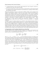
2.2 Rotating annular stream tube analysis
Thus far the method is developed on the assumption that there was no rotational motion. To
extend the method developed, the effects of this rotational motion needs to be included so it
is necessary to modify the qualities of the actuator disk by assuming that it can also impart a
Fig. 2. Title Rotating Annular Stream Tube Analysis
Aerodynamics of Wind Turbines
7
rotational component to the fluid velocity while the axial and radial components remain
unchanged. Using a rotating annular stream tube analysis, equations can be written that
express the relation between the wake velocities (both axial and rotational) and the
corresponding wind velocities at the rotor disk.
This analysis considers the conservation of angular momentum in the annular stream tube
(Fig. 2). If the condition of continuity of flow is applied for the annular element taken on the
rotor plane Eqn 24 can be written.
(24)
Applying the conservation of the angular momentum on upstream and the wake region of
the flow domain gives
(25)
Also the torque caused by the angular momentum balance on the differential annular
element can be obtained using Eqn 26.
(26)
where 2. Also applying the Bernoulli equation between station 1 and 2 then
between 3 and 4 gives Bernoulli’s constants as
1
2
1
2
1
2
1
2
And taking the difference between these constants gives
1
2
Which means the kinetic energy of the rotational motion given to the fluid by the torque of
the blade is equal to 1/2
. So the total pressure head between both sides of the
rotor becomes
1
2
∞
1
2
1
2
∞
1
2
′
(27)
Applying the Bernoulli’s equation between station 2 and 3 gives the pressure drop as
1
2
2
(28)
Substituting this result into the equation 27 gives
1
2
2
(29)
Fundamental and Advanced Topics in Wind Power
8
In station 4, the pressure gradient can be written as
(30)
Differentiating Eqn 29 relative to r
and equating to equation 30 gives
1
2
(31)
The equation of axial momentum for the given annular blade element in differential form
can be written as
(32)
Since dTp
dA, Eqn 32 can be written as Eqn 33.
2
(33)
Finally, combining Eqn 24, 27, 32 and 33 gives
1
2
/2
/2
(34)
An exact solution of the stream-tube equations can be obtained when the flow in the
slipstream is not rotational except along the axis which implies that the rotational
momentum wr
has the same value for all radial elements. Defining the axial velocities as
uU
1a
andu
U
1b
gives
(35)
Also the thrust on the differential element is equal to
(36)
Using Eqn 28 Eqn 36 can be rewritten as
(37)
If the angular induction factor is defined asa
, then dT becomes
(38)
In order to obtain a relationship between axial induction factor and angular induction factor,
Eqn 37 and 38 can be equated which gives
Aerodynamics of Wind Turbines
9
(39)
Using Eqn 26 the torque on the differential element can be calculated as
(40)
The power generated at each radial element is given by dPΩdQ. Substituting Eqn 40 into
this equation gives
(41)
Also the power coefficient for each differential annular ring can be written as
(42)
Substituting Eqn 41 into the Eqn 42 and integrating from hub tip speed ratio to the tip speed
ratio gives power coefficient for the whole rotor.
(43)
By solving Eqn 39 for a
in terms ofa Eqn 44 can be obtained.
(44)
Solving the equations 43 and 44 together for the maximum possible power production gives
(45)
Also substituting Eqn 45 into Eqn 39 gives the angular induction factor for maximum power
in each annular ring.
(46)
Differentiating Eqn 45 with respect to axial induction factor at rotor plane, a relationship
between r, dλ and da can be obtained.
(47)
Finally, substituting the Eqn 45, 46, 47 into the Eqn 43 gives the maximum power coefficient
of the rotor
(48)
Fundamental and Advanced Topics in Wind Power
10
Where a
is the corresponding axial induction factor for λ
λ
and a
is the corresponding
axial induction factor for λ
λ.
2.3 Blade element theory
Until this point the momentum theory is tried to be explained on account of HAWT rotor
design but it does not consider the effects of rotor geometry characteristics like chord and
twist distributions of the blade airfoil. For this reason blade element theory needs to be
added to the design method. In order to apply blade element analysis, it is assumed that the
blade is divided into N sections. This analysis is based on some assumptions including no
aerodynamic interactions between different blade elements and the forces on the blade
elements are solely determined by the lift and drag coefficients.
Fig. 3. Rotating Annular Stream Tube
Since each of the blade elements has a different rotational speed and geometric
characteristics they will experience a slightly different flow. So blade element theory
involves dividing up the blade into a sufficient number (usually between ten and twenty) of
elements and calculating the flow at each one (Fig. 3, 4). Overall performance characteristics
of the blade are then determined by numerical integration along the blade span.
Fig. 4. The Blade Element Model
Aerodynamics of Wind Turbines
11
Lift and drag coefficient data are available for a variety of airfoils from wind tunnel data. Since
most wind tunnel testing is done with the aerofoil stationary, the relative velocity over the
airfoil is used in order to relate the flow over the moving airfoil with the stationary test (Fig. 5).
Fig. 5. Blade Geometry for the analysis of a HAWT Rotor
Examining Fig. 5, the following equations can be derived immediately.
(49)
(50)
(51)
(52)
(53)
Fundamental and Advanced Topics in Wind Power
12
(54)
If the rotor has B number of blades, Eqn 49, 51 and 52 can be rearranged.
(55)
(56)
The elemental torque can be written as dQrdL which gives Eqn 57.
(57)
Also Eqn 58 can be derived by examining Fig. 5.
(58)
The solidity ratio can be defined as
(59)
Finally, the general form of elemental torque and thrust equations becomes
(60)
(61)
Eqn 60 and Eqn 61 define the normal force (thrust) and the tangential force (torque) on
annular rotor section respectively.
2.4 Blade Element Momentum (BEM) theory
As it is stated before BEM theory refers to the determination of a wind turbine blade
performance by combining the equations of general momentum theory and blade element
theory, so Eqn 36 and 61 can be equated to obtain the following expression.
(62)
Also equating Eqn 40 and 60 in the same manner gives
Aerodynamics of Wind Turbines
13
(63)
By rearranging Eqn 63 and combining it with Eqn 50
(64)
can be written. In order to calculate the induction factors and ′, C
can be set to zero.
Thus the induction factors can be determined independently from airfoil characteristics.
Subsequently, Eqn 62, 63 and 64 can be rewritten as Eqn 65, 66, and 67 respectively.
(65)
(66)
(67)
Finally, by rearranging Eqn 65, 66 and 67 and solving it for and ′, the following useful
analytical relationships can be obtained.
(68)
(69)
(70)
(71)
The total power of the rotor can be calculated by integrating the power of each differential
annular element from the radius of the hub to the radius of the rotor.
(72)
And rewriting the power coefficient given in Eqn 18 using Eqn 72 gives