ARNOLD, K. (1999). Design of Gas-Handling Systems and Facilities (2nd ed.) Episode 2 Part 2 pps
Bạn đang xem bản rút gọn của tài liệu. Xem và tải ngay bản đầy đủ của tài liệu tại đây (1.53 MB, 25 trang )
1.
Fully-enclosed
camshaft
is
built
in
sections
for
easy removal.
frame
top is
bored,
and the
precision-machined
cylinder
extension
is
2.
Crosshead guides
are
cast
integrally with engine
frame.
provided with
O-rings.
3.
He
toil
compressor
valves
for any
service
selected
from the
14,
water
jackets
are
provided
with removable
cover
plates
for
unmatched
Dresser-Rand
line,
including
famous
gas-cushioned
inspection.
Channel
Valves.
r
1
).
Pistons
are
precision-ground
for a
perfect
fit in a
honed cylinder
4.
Clearance
pockets
and
other
types
of
capacity
control
devices
are
liner
bore.
Long-skirt,
lightweight
piston
reduces
wear.
available
to
suit
any
application.
1o,
For
sustained
low
oil
consumption,
narrow,
deep-groove
piston
rings
5.
Compressor
cylinders
(dry
or
water-cooled)
of
cast
iron,
nodular
conform easily
to
liner
walls.
Top
compression
ring is
chrome-plated
iron,
or
forged
steel
are
engineered
to
suit
required
pressures
and to
condition liners during break-in.
capacities.
17,
Fuel
gas
headers,
one for
each bank
of
power cylinders,
are
6.
Full-floating
packing
adjusts
itself
in
operation
and
assures
best
seal
controlled
by
common automatic
valve
and
safer/
devices.
Orifice
with minimum wear. Packing
is
pressure-lubricated
and
vented. plates
equalize
the
distribution
of gas to
each
of the
cylinders.
7. Oil
wiper
rings
remove
excess
oil from
piston
rod and
seal
the
Individual
adjustments
are
eliminated.
frame.
13.
Simple fuel
injection
valves
are
operated
from
single
camshaft.
8.
Crossheads,
running
in
bored
guides,
have
shim-adjusted
babbitted
19.
Long-life special
alloy
valves have chromium-plated
stems,
hardened
shoes
at top and
bottom
and
either
full-floating
or fixed
crosshead
shrink-f
it
valve seats,
and
replaceable
guides.
pins.
Suitable
for
addition
of
balance weights.
20.
Common
air
inlet manifold
conducts
air from
turbochargers
to
each
9.
Simple,
low-cost
foundation, made
possible
by the
smaller
size,
power cylinder.
lighter weight,
and
smooth
running blance
of the
KVSR.
21.
Large
covers
give
easy
access
to
valve gear, exclude
dust
and
dirt,
10.
Large
frame
openings
give
ample
and
unrestricted
access
to 22.
Water-jacketed
exhaust eliminate expansion strains
and
crankcase.
keep
engine
room temperature down.
11.
Flywheel-mounted ring gear
for
starting
motors
permits cranking
23.
Fitted
with
a
reliable
Altronic
II CPU
solid
slate
tow tension
with
either
air or gas
between
150
psi and 225
psi
supply pressure.
breakerless
ignition
system,
12.
alloy-iron
frame and top are
well
reinforced with
cast-in
ribs, 24. The
engine
can be
fitted with either hydraulic
or
electronic
governor
Integrally
cast
bulkheads hold main bearings
on
both
sides
of
every
systems
to
control
engine
speed
crankthrow.
Keys,
double-bolting,
ami
Me
rods
are
used
to
secure
25. in
recent years, each power
head
is fitted
with
a
bolt-in
pre-
tfie
frame
ami
frame top
together
as a
solid structure. combustion chamber, which allows
the
engine
to
burn
a
very
lean
13.
To
assure oil-tight
joints
between power cylinders
and frame top, the
mixture, resulting
in
very
bw
exhaust
emissions
262
Design
of
GAS-HANDLING
Systems
and
Facilities
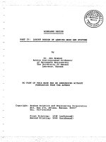
Figure
10-5.
Integral
engine
compressor.
(Courtesy
of
Cooper
Industries
Energy
Services
Group.)
sidered low-speed units. They tend
to
operate
at
400-600
rpm,
although
some operate
as low as 200
rpm.
Figure
10-5
shows
a
very large integral compressor. This
would
be
typical
of
compressors
in the
2,000
hp to
13,000
hp
size.
The
size
of
this
unit
can be
estimated
by the
height
of the
handrails above
the
compressor
cylinder
on the
walkway that provides access
to the
power cylinders,
This
particular unit
has
sixteen power cylinders (eight
on
each side)
and
four
compressor cylinders.
It
should
be
obvious that
one of
these large integrals would require
a
very
large
and
expensive foundation
and
would have
to be
field
erected.
Often,
even
the
compressor cylinders must
be
shipped separate
from
the
frame
due to
weight
and
size limitations. Large integrals
are
also
much
more
expensive than either high-speeds
or
centrifugals.
For
this reason, even though they
are the
most
fuel
efficient
choice
for
large
horsepower needs, large integrals
are not
often
installed
in oil and
gas
fields. They
are
more common
in
plants
and
pipeline booster service
where
their
fuel
efficiency,
long
life,
and
steady performance outweigh
their
much higher cost.
There
are
some
low
horsepower
(140
to
360)
integrals that
are
normal-
ly
skid mounted
as
shown
in
Figure
10-6
and
used extensively
in
small
oil
fields
for
flash
gas or
gas-lift compressor
service.
In
these units
the
power
cylinders
and
compressor cylinders
are
both mounted
horizontally
Comp
res
so
t~s
263
Figure
10*6.
Small-horsepower
skid-mounted
integrals.
(Courtesy
of
Cooper
Industries,}
and
opposed
to
each other. There
may be one or two
compressor
cylin-
ders
and one to
four
power cylinders. They operate
at
very slow speed.
Their cost
and
weight
are
more than similar sized high-speed
separable
units,
but
they have lower maintenance cost, greater
fuel
efficiency,
and
longer
life
than
the
high speeds.
264
Design
of
GAS-HANDLING
Systems
and
Facilities
The
major
characteristics
of
low-speed
reciprocating compressors are:
Size
•
Some
one and two
power cylinder field
gas
compressors rated
for
L40
hp
to 360
hp.
»Numerous
sizes from
2,000
hp to
4,000
hp.
•
Large sizes
2,000
hp
increments
to
12,000
hp.
•
2 to
10
compressor cylinders common.
Ac^antages
•
High
fuel
efficiency
(6-8,000
Btu/bhp-hr).
•
High efficiency compression over
a
wide range
of
conditions.
•
Long operating life.
• Low
operation
and
maintenance cost when compared
to
high speeds.
Disadvantages
•
Usually must
be
field erected except
for
very small sizes.
•
Requires heavy foundation.
•
High installation cost.
•
Slow speed requires high degree
of
vibration
and
pulsation suppression.
Vane-Type
Rotary
Compressors
Rotary
compressors
are
positive-displacement
machines.
Figure
10-7
shows
a
typical vane compressor.
The
operation
is
similar
to
that
of a
vane
pump shown schematically
in
Figure 10-10
of
Volume
1, 2nd
Edi-
tion
(Figure
10-9
in 1st
Edition).
A
number
of
vanes, typically from
8 to
20, fit
into slots
in a
rotating
shaft.
The
vanes slide into
and out of the
slots
as the
shaft
rotates
and the
volume contained between
two
adjacent
vanes
and the
wall
of the
compressor cylinder
decreases.
Vanes
can be
cloth
impregnated with
a
phenolic resin, bronze,
or
aluminum.
The
more
vanes
the
compressor has,
the
smaller
the
pressure differential
across
the
vanes. Thus, high-ratio vane compressors tend
to
have more vanes than
low-ratio compressors.
A
relatively large quantity
of oil is
injected into
the flow
stream
to
lubricate
the
vanes. This
is
normally captured
by a
discharge cooler
and
after-scrubber
and
recycled
to the
inlet.
Compressors
265
Figure
10-7.
Vane-type
rotary
compressor.
[Courtesy
of
Dresser-Rand
Company,}
Vane
compressors
tend
to be
limited
to low
pressure
service,
generally
less
than
100 to 200 psi
discharge. They
are
used extensively
as
vapor
recovery
compressors
and
vacuum pumps. Single-stage vane compressors
can
develop
27 in. Hg
vacuums, two-stage compressors
can
develop
29,9
in.
Hg, and
three-stage
compressors
can
develop even higher vacuums.
The
major characteristics
of
vane
compressors
are:
Size
•
Common sizes
up to 250
bhp,
but
mostly used
for
applications
under
125bhp.
•
Available
in
sizes
to 500
bhp.
•
Discharge
pressures
to 400
psig.
•
Single-
or
two-stage
in
tandem
on
same
shaft.
Advantages
•
Good
in
vacuum service.
• No
pulsating
flow.
•
Less
space.
•
Inexpensive
for low
hp
vapor recovery
or
vacuum service.
266
Design
of
GAS-HANDLING
Systems
and
Facilities
Disadvantages
•
Must have clean
air or
gas.
«Takes
5 to 20%
more horsepower than reciprocating.
*
Uses
ten
times
the oil of a
reciprocating. Usually install after-cooler
and
separator
to
recycle oil.
Helical-Lobe
(Screw)
Rotary
Compressors
Screw compressors
are
rotary positive displacement machines.
Two
helical rotors
are
rotated
by a
series
of
timing gears
as
shown
in
Figure
10-8
so
that
gas
trapped
in the
space between them
is
transported
from
the
suction
to the
discharge piping.
In
low-pressure
air
service,
non-lubri-
cated screw compressors
can
deliver
a
clean, oil-free air.
In
hydrocarbon
service most screw compressors require that liquid
be
injected
to
help
provide
a
seal. After-coolers
and
separators
are
required
to
separate
the
seal
oil and
recirculate
it to
suction.
Screw compressors
can
handle moderate amounts
of
liquid. They
can
also handle
dirty
gases because there
is no
metallic contact
within
the
casing.
Figure
10-8.
Screw-type
rotary
compressor.
{Courtesy
of
Dresser-Rand
Company.)
Compressors
267
It
tends
to be
limited
to 250
psig discharge pressures
and a
maximum
of
400
hp
in
hydrocarbon service, although machines
up to
6,000
hp are
avail-
able
in
other service. Screw compressors
are not as
good
as
vane compres-
sors
in
developing
a
vacuum, although they
are
used
in
vacuum service,
Non-lubricated
screw compressors have very close clearances
and
thus
they
are
designed
for
limited ranges
of
discharge temperature,
tempera-
ture
rise,
compression
ratio,
etc.,
all of
which
can
cause changes
in
these
clearances. Lubricated compressors have
a
somewhat broader tolerance
to
changes
in
operating conditions,
but
they
are
still more limited
than
reciprocating compressors.
The
major
characteristics
of
screw compressors are:
Size
«
Up to
6,000
hp in air
service,
but
more common below
800 hp,
•
Up to 400 hp in
hydrocarbon service,
•
Discharge pressures
to 250
psig.
«
Single-
or
two-stage
in
tandern
on
same
shaft.
Advantages
«Available
as
non-lubricated
especially
for air
service.
•
Can
handle dirty gas.
• Can
handle moderate amounts
of
liquids,
but no
slugs.
• No
pulsating
flow.
•
At low
discharge pressure (<50 psig)
can be
more
efficient
than reci-
procating.
Disadvantages
• In
hydrocarbon service needs seal
oil
with
after-cooler
and
separator
to
recycle
oil.
• At
discharge pressure over
50
psig takes
10
to 20%
more horsepower
than
reciprocating.
• Low
tolerance
to
change
in
operating
conditions
of
temperature,
pressure,
and
ratio.
Centrifugal
Compressors
Similar
to
multistage centrifugal pumps, centrifugal compressors,
as
shown
in
Figure 10-9,
use a
series
of
rotating impellers
to
impart
velocity
268
Design
of
GAS-HANDLING
Systems
and
Facilities
Figure
TO-9.
Centrifugal
compressor.
{Courtesy
of
Dresser-Rand
Company,!
head
to the
gas.
This
is
then converted
to
pressure head
as the gas is
slowed
in the
compressor case. They
are
either turbine
or
electric motor
driven
and
range
in
size
from
1,000
hp to
over
20,000
hp.
Most
larger
compressors (greater than
4,000
hp)
tend
to be
turbine-driven centrifugal
compressors because there
is
such
a
first
cost advantage
in
that size range
over integrals. Centrifugal compressors have high ratios
of
horsepower
per
unit
of
space
and
weight, which makes
them
very popular
for
off-
shore applications.
As
shown
in
Figure
10-10
they
can be
either horizontally split
case
or
vertically split case (barrel).
To
develop
the
required
gas
velocities
and
head they must rotate
at
very high speeds (20,000
to
30,000
rprn),
making
the
design
of
driver, gear,
and
compressor extremely important. Turbine
drives
are
also high speed
and a
natural match
for
centrifugal compressors.
There
is a
disadvantage
in
centrifugal machines
in
that they
are low
efficiency.
This means
it
requires more brake horsepower
(bhp)
to
com-
press
the
same
flow
rate than would
be
required
for a
reciprocating com-
pressor.
If the
compressor
is
driven with
a
turbine, there
is
even
a
greater
disadvantage because
the
turbines
are low in
fuel
efficiency.
The net
result
is
that turbine-driven centrifugal machines
do not use
fuel
very
Comp
res
so
rs
269
Figure
10-10.
Horizontally split
centrifugal
compressor
(top)
and
vertically
split
centrifugal
compressor,
barrel
(bottom).
{Courtesy
of
Dresser-Rand
Company.)
270
Design
of
GAS-HANDLING
Systems
and
Facilities
efficiently.
This
fuel
penalty
can be
overcome
if
process heat
is
needed.
Waste
heat
can be
recovered from
the
turbine exhaust, decreasing
or
eliminating
the
need
to
burn
gas to
create process heat.
As
with
electric motor
and
engine-driven
high-speeds, turbine
and
elec-
tric
motor-driven centrifugals
can be
easily packaged
for use in oil and
gas
fields.
They
are
very common
in
booster compressor service
(high
volume,
low
ratio)
and for
very high
flow
rate gas-lift service.
Centrifugal
compressors cannot
be
used
for
high ratio,
low-volume
applications.
The
major
characteristics
of
centrifugal
compressors are:
Size
«
Starts about
500
hp.
*
1,000
hp
increments
to
20,000
hp.
Advantages
*
High horsepower
per
unit
of
space
and
weight.
*
Turbine drive easily
adapted
to
waste-heat recovery
for
high
fuel
efficiency.
*
Easily automated
for
remote operations.
*
Can be
skid mounted, self-contained.
*
Low
initial cost.
»
Low
maintenance
and
operating cost.
*
High availability factor.
»
Large capacity available
per
unit.
Disadvantages
*
Lower compressor efficiency.
*
Limited
flexibility for
capacity.
*
Turbine drives have higher
fuel
rate than reciprocating units.
*
Large horsepower units mean that outage
has
large
effect
on
process
or
pipeline capabilities.
SPECIFYING
A
COMPRESSOR
In
specifying
a
compressor
it is
necessary
to
choose
the
basic type,
the
number
of
stages
of
compression,
and the
horsepower required.
In
order
Compressors
271
to
do
this
the
volume
of
gas, suction
and
discharge pressure,
suction
tem-
perature,
and gas
specific gravity must
be
known.
The
detailed
calculation
of
horsepower
and
number
of
stages depends
upon
the
choice
of
type
of
compressor,
and the
type
of
compressor
depends
in
part upon
horsepower
and
number
of
stages.
A
first
approxi-
mation
of the
number
of
stages
can be
made
by
assuming
a
maximum
compressor ratio
per
stage
of 3,0 to 4.0 and
choosing
the
number
of
stages
such
that:
where
R =
ratio
per
stage
n
=
number
of
stages
P
(
j
=
discharge pressure, psia
P
s
=
suction
pressure,
psia
A
first
approximation
for
horsepower
can be
made
from
Figure
10-11
or
from
the
following
equation:
where
BHP
=
approximate brake horsepower
R
=
ratio
per
stage
n
=
number
of
stages
F = an
allowance
for
interstage pressure drop
=
LOO
for
single-stage compression
1.08
for
two-stage
compression
1.10
for
three-stage
compression
Q
g
= flow
rate, MMscfd
Once
the
required horsepower
and
number
of
stages
are
estimated,
a
choice
of
compressor type
can be
made
from
the
considerations included
earlier.
Some
example selections
are
included
in
Table
10-1.
The
selec-
tions listed
in
this table
are
meant
as
common types that would normally
be
specified
for the
given
conditions.
It
must
be
emphasized that these
are
not
recommendations that should
be
accepted without consideration
of the
advantages
and
disadvantages listed earlier.
In
addition,
local
foundation
conditions, type
of
drivers available, cost
of
fuel,
availability
of
spare
272
Design
of
GAS-HANDLING
Systems
and
Facilities
Figure
10-11.
Curve
for
estimating
compression
horsepower.
(Reprinted
wirfi
permission
from
GPSA
Engineering
Data
Book,
Wth
Ed.)
parts
and
personnel
familiar
with
operating
and
maintenance, waste heat
requirements, etc., could
influence
the
selection
for a
specific installation.
Procedure
for
More
Accurate
Determination
of
Horsepower
and
Number
of
Stages
There
are
economic
and
operational reasons
for
considering
an
addi-
tional
stage
of
compression.
The
addition
of a
stage
of
compression
requires
an
additional
scrubber, additional
cylinder
or
case,
and
more
complex
piping
and
controls.
In
addition, there
are
some horsepower
losses
due to
additional mechanical friction
of the
cylinder
or
rotating
element
and the
increased pressure drop
in the
piping. This horsepower
loss
and
additional equipment cost
may be
more than
offset
by the
increased
efficiency
of
compression.
Comp
res
so
rs
2
73
Table
10-1
Example
Compressor Type Selections
Service
Booster
Gas
Lift
Flash
Gas
Vapor
Recovery
Flow
Rate
MMscfd
100
10
5
20
100
2
2
4
0.1
1.0
2.0
R
2.0
2.0
2.7
2,7
2.7
2.0
2.0
2.0
4.0
3.0
3.0
n
1
!
3
3
.3
1
2
2
1
2
2
Approx.
bhp
4,400
440
980
3,920
19,602
88
190
380
9
143
286
Most
Likely
Centrifugal
High
Speed
High Speed
Centrifugal
Centrifugal
Screw
High
Speed
High
Speed
Vane
Screw
High
Speed
Selection
Alternate
Integral
(onshore
only)
Integral
(onshore only)
High Speed
Screw
Screw
Vane
Screw
Figure
10-12
shows
the
pressure-volume
curve
for
both
single
stage
compression
and two
stage
compression
(neglecting interstage
losses).
By
adding
the
second stage
and
cooling
the gas
from
A to D
before
beginning
the
compression cycle
in the
second
stage,
the
area under
the
curve
is
reduced
by an
amount equal
to
A-B-C-D.
This represents
the
power saved
by
adding
the
second stage.
It
is
often
even more important
to add an
additional stage
in
order
to
limit
the
discharge temperature
of any one
stage.
It
is
clear
from
Figure
10-12
that because
of the
cooling
that
occured
in the
interstage
(A to D)
the
gas at C is
cooler than
it
would have been
at
point
B.
The
discharge temperature
for any
single stage
of
compression
can be
calculated
from:
where
T
d
=
stage discharge temperature,
°R
T
s
=
stage suction temperature,
°R
P
d
=
stage discharge pressure, psia
P
s
=
stage suction pressure,
psia
274
Design
of
GAS-HANDLING
Systems
and
Facilities
Figure
10-12.
Horsepower reduction
by
multistaging
(neglects interstage losses).
k
=
ratio
of gas
specific heats,
Cp/C
v
T|
=
polytropic
efficiency
= 1.0 for
reciprocating,
0.8 for
centrifugal
It
is
desirable
to
limit discharge temperatures
to
below
250°F
to
275°F
to
ensure
adequate packing
life
for
reciprocating compressors
and to
avoid
lube
oil
degradation.
At
temperatures above
300°F
eventual lube
oil
degradation
is
likely,
and if
oxygen
is
present ignition
is
even possible.
Under
no
circumstances should
the
discharge temperature
be
allowed
to
exceed 350°F.
The
discharge temperature
can be
lowered
by
cooling
the
suction
gas
and
reducing
the
value
of
P</P
S
,
that
is, by
adding more stages
of
com-
pression.
The
brake horsepower
per
stage
can be
determined
from:
Compressors
275
where
BHP
=
brake horsepower
per
stage
Q
g
=
volume
of
gas,
MMscfd
T
s
==
suction temperature,
°R
Z
s
=
suction compressibility
factor
Z
D
=
discharge compressibility
factor
E =
efficiency
high-speed
reciprocating units
— use
0.82
low-speed
reciprocating
units
— use
0.85
centrifugal
units
— use
0.72
Tj
=
polytropic
efficiency
k
=
ratio
of gas
specific heats,
Cp/C
v
P
s
=
suction pressure
of
stage, psia
P
d
=
discharge
pressure
of
stage,
psia
Zav
=
(Z
s
+
Z
D
)/2
The
total horsepower
for the
compressor
is the sum of the
horsepower
required
for
each stage
and an
allowance
for
interstage pressure
losses.
It
is
assumed
that
there
is a 3%
loss
of
pressure
in
going
through
the
cooler,
scrubbers, piping,
etc.,
between
the
actual discharge
6f
the
cylinder
and
the
actual suction
of the
next
cylinder.
For
example,
if the
discharge pres-
sure
of the
first
stage
is 100
psia,
the
pressure loss
is
assumed
to be 3
psia
and the
suction pressure
of the
next stage
is 97
psia.
That
is,
second
stage suction pressure
is not
equal
to the
first
stage discharge pressure.
The
following
procedure
can now be
used
to
calculate
the
number
of
stages
of
compression
and the
horsepower
of the
unit:
•
First, calculate
the
overall compression ratio
(R
t
=
Pd/P
s
)-
If the
com-
pressor
ratio
is
under
5,
consider
using
one
stage.
If it is
not,
select
an
initial
number
of
stages
so
that
R < 5. For
initial calculations
it can
be
assumed
that
ratio
per
stage
is
equal
for
each
stage.
•
Next, calculate
the
discharge
gas
temperature
for the first
stage.
If the
discharge temperature
is too
high (more than
300°F),
a
large enough
number
of
stages
has not
been selected
or
additional cooling
of the
suction
gas is
required.
If the
suction
gas
temperature
to
each stage
cannot
be
decreased, increase
the
number
of
stages
by one and
recal-
culate
the
discharge temperature.
•
Once
the
discharge temperature
is
acceptable, calculate
the
horse-
power
required,
and
calculate suction pressure, discharge
tempera-
ture,
and
horsepower
for
each succeeding stage.
276
Design
of
GAS-HANDLING
Systems
and
Facilities
»If
R > 3,
recalculate, adding
an
additional stage
to
determine
if
this
could result
in a
substantial savings
on
horsepower,
RECIPROCATING
COMPRESSORS—PROCESS
CONSIDERATIONS
Figure
10-13
is a
generalized process
flow
diagram
of a
single stage
reciprocating compressor.
The
following items should
be
considered
in
developing
a
process
flow:
Recycle
Valve
Most
gas
lift,
flash
gas,
and
vapor recovery compressors require
a
recycle
valve because
of the
unsteady
and
sometimes unpredictable
nature
of the flow
rate. Indeed there
may be
periods
of
time when there
is
no
flow at all to the
compressor.
At
a
constant speed,
a
constant volume
of gas (at
suction conditions
of
pressure
and
temperature) will
be
drawn into
the
cylinder.
As the flow
rate
to
the
compressor
decreases,
the
suction pressure
decreases
until
the gas
available
expands
to
satisfy
the
actual volume required
by the
cylinder.
When
the
suction pressure
decreases,
the
ratio
per
stage
increases
and
therefore
the
discharge temperature increases.
In
order
to
keep
from
having
too
high
a
discharge temperature,
the
recycle valve opens
to
help
fill the
compressor
cylinder volume
and
maintain
a
minimum
suction pressure,
Flare
Valve
As
flow
rate
to the
compressor increases,
the
suction pressure rises
until
the
volume
of gas at
actual conditions
of
temperature
and
pressure
compressed
by the
cylinder
equals
the
volume required
by the
cylinder.
A
flare
valve
is
needed
to
keep
the
suction pressure
from
rising
too
high
and
overpressuring
the
suction cylinder, creating
too
high
a rod
load
or
increasing
the
horsepower requirements beyond
the
capability
of the
dri-
ver
(see Chapter
11
for
further
discussion).
The flare
valve also allows production
to
continue momentarily
if a
compressor
shuts down automatically. Even
in
booster
service
it may be
beneficial
to
allow
an
operator
to
assess
the
cause
of the
compressor
shutdown
before shutting
in the
wells.
In flash gas or
gas-lift
service,
it is
almost
always
beneficial
to
continue
to
produce
the
liquids while
the
Figure
10-13.
Example
process
flow
diagram
of
reciprocating
compressor.
278
Design
of
GAS-HANDUNG
Systems
and
Facilities
cause
of the
compressor shutdown
is
investigated.
The
flare
valve must
always
be
installed upstream
of the
suction shutdown valve,
Suction Pressure
Throttle
Valve
A
suction pressure throttling valve
can
also
be
installed
to
protect
the
compressor
from
too
high
a
suction pressure. This
is
typically
a
butterfly
valve
that
is
placed
in the
suction piping.
As
flow
rate
to the
compressor
increases,
the
valve will close slightly
and
maintain
a
constant suction
pressure.
This will automatically limit
the
flow
rate
to
exactly
that
rate
where
the
actual volume
of gas
equals that required
by the
cylinder
at the
chosen suction pressure setting.
It
will
not
allow
the
suction pressure
to
increase
and the
compressor cylinder
to
thus handle more
flow
rate.
The
pressure upstream
of the
suction valve
will
increase until
sufficient
back-pressure
is
established
on the
wells
or
equipment feeding
the
com-
pressor
to
reduce
the flow to a
new
rate
in
equilibrium with that being
handled
by the
cylinder
or
until
a flare
valve
or
relief valve
is
actuated.
Suction throttle valves
are
common
in
gas-lift service
to
minimize
the
action
of the
flare valve. Flow from gas-lift wells decreases with
increased
back-pressure.
If
there were
no
suction valve,
the flare
valve
may
have
to be set at a low
pressure
to
protect
the
compressor.
With
a
suction
valve
it may be
possible
to set the flare
valve
at a
much higher
pressure
slightly below
the
working pressure
of the
low-pressure separa-
tor.
The
difference between
the
suction valve
set
pressure
and the flare
valve
set
pressure provides
a
surge volume
for gas and
helps even
the
flow
to
the
compressor.
Speed Controller
A
speed controller
can
help extend
the
operating range
and
efficiency
of
the
compressor.
As the flow
rate increases,
the
compressor speed
can be
increased
to
handle
the
additional
gas.
Compressor speed will stabilize
when
the
actual
flow
rate
to be
compressed equals
the
required
flow
rate
for
the
cylinder
at the
preset suction pressure.
As the flow
rate decreases,
the
compressor slows until
the
preset
suction pressure
is
maintained.
A
speed
controller
does
not
eh'minate
the
need
for a
recycle valve,
flare
valve,
or
suction throttling valve,
but it
will
minimize their
use.
The
recycle
valve
and
suction throttling valve
add
arbitrary loads
to the
compressor
and
thus
increase
fuel
usage.
The flare
valve leads
to a
direct waste
of
reservoir
fluids
and
thus
loss
of
income.
For
this reason, engine speed control
is
rec-
Compressors
279
ommended
for
most medium
to
large
size
(>500
hp)
reciprocating compres-
sors
where
a
constant
flow
rate cannot
be
ensured
by the
process.
Slowdown
Valve
A
blowdown valve relieves trapped pressure when
the
compressor
is
shut
down
due to a
malfunction
or for
maintenance.
The
flowsheet shows
an
automatic blowdown
valve.
Most operators require automatic blowdown valves
so
that
if the
com-
pressor
shuts down
due to a
malfunction,
the
trapped
gas
will
not
become
a
potential
hazard.
On
some small onshore compressors some operators
prefer
manual valves
to
make
it
easier
to
restart
the
compressor.
The
compressor
is
only blown down
for
maintenance.
Often,
the
blowdown valve
is
routed
to a
closed
flare
system, which
services other relief valves
in the
facility
to
ensure that
all the gas is
vent-
ed
or flared at a
safe
location.
In
such instances,
a
separate manual blow-
down valve
piped
directly
to
atmosphere,
with nothing
else
tied
in, is
also
needed.
After
the
compressor
is
shut down
and
safely blown down
through
the flare
system,
the
normal blowdown valve must
be
closed
to
block
any gas
that
may
enter
the flare
system
from
other relief valves.
The
manual blowdown valve
to
atmosphere protects
the
operators
from
small
leaks into
the
compressor
during maintenance operations.
Suction
and
Discharge
Shut-down
Valves,
Discharge
Check
These
valves
isolate
the
compressor. Most operators require both
shut-
down
valves
to be
automatic. Some operators
use
manual valves
on
small
onshore
compressors.
If the
compressor
is in a
building
it is
preferable
to
locate
the
valves
outside
the
building.
Relief
Valve
on
Each
Cylinder
Discharge
Each cylinder
discharge
line
should have
a
relief
valve
located
upstream
of the
cooler. Like
all
reciprocating devices,
the
piston
will
continue
to
increase
pressure
if flow is
blocked.
The
relief
valve assures
that
nothing
is
overpressured.
It
must
be
located upstream
of the
coolers
as
ice can
form
in the
coolers,
blocking
flow.
Pulsation
Bottles
Each
cylinder should have suction
and
discharge pulsation bottles
to
dampen
the
acoustical vibrations caused
by the
reciprocating
flow.
280
Design
of
GAS-HANDLING
Systems
and
Facilities
Discharge
Coolers
These cool
the
interstage gas. They
may
also
be
required
to
cool
the
discharge
gas
prior
to gas
treating
or
dehydration
or to
meet pipeline
specifications.
Typically,
aerial
coolers
are
used
in
these situations.
Suction
Scrubbers
Suction
scrubbers
are
required
on the
unit
suction
to
catch
any
liquid
carry-overs
from
the
upstream equipment
and any
condensation caused
by
cooling
in the
lines leading
to the
compressor. They
are
also required
on
all the
other stages
to
remove
any
condensation
after
cooling.
On
each
suction
scrubber
a
high
level
shut-down
is
required
so
that
if any
liquids
do
accumulate
in the
suction scrubber,
the
compressor will automatically
shut
down before liquids carry-over
to the
compressor cylinders.
CENTRIFUGAL
COMPRESSORS—SURGE
CONTROL
AND
STONEWALLING
Surge
is the
most important process design consideration
for
centrifu-
gal
compressors.
The
surge condition occurs when
the
compressor does
not
have enough
flow to
produce
sufficient
head.
At
this point,
the gas in
the
discharge piping
flows
back into
the
compressor momentarily. This
lowers
the
back-pressure
of the
system, establishing forward
flow at a
temporarily
low
head.
The
cycling
from
zero,
or
even backward
flow to
forward
flow, is
called
"surge"
and is
very
detrimental
to the
compressor
bearings
and
seals. Most compressors
can
only sustain
a
very
few
cycles
of
surge before severe mechanical problems develop.
Surge
may be
caused
by an
increase
in
head requirement
or a
loss
in
throughput.
Figure
10-14
shows
the
capacity curves
for a
typical com-
pressor.
The
surge line
for
this particular compressor
is
shown.
Any
com-
bination
of
speed, pressure,
and flow
rate
to the
right
of the
surge line
is
acceptable. Typically,
a
surge control line offsetting
the
theoretical surge
limit
given
by the
manufacturer
is
used
to
establish
set
points
for a
con-
trol
system
adjusting speed
and
recycle
as
shown
in
Figure
10-16.
A
stonewall
or
choked
flow
condition occurs when sonic velocity
is
reached
at the
exit
of a
compressor wheel. When this point
is
reached,
flow
through
the
compressor cannot
be
increased even
with
further
Compressors
281
Figure
10-14.
Typical
centrifugal
compressor
curve
showing surge.
increase
in
suction pressure.
If
this occurs,
the
suction
pressure will rise,
Operation
in
this region will cause excessive
use of
horsepower, occa-
sionally
to the
point
of
overload,
and
frequent
flaring.
If
higher
flow
rates
are
desired, modifications
to the
impeller must
be
made,
as
shown
in
Figure
10-15.
CENTRIFUGAL
COMPRESSORS
PROCESS
CONSIDERATIONS
Figure
10-16
is a
generalized process
flow
diagram
of a
single-stage
centrifugal
compressor.
The
following
items
should
be
considered
in
developing
a
process
flow:
Recycle
(Surge
Control) Valve
A
recycle valve
is
needed
for
surge control
as
well
as for the
condi-
tions listed above
for
reciprocating compressors.
At
constant speed
the
head-capacity
relationship will vary
in
accordance
with
the
performance
curve.
For
a
constant compressor speed:
282
Design
of
GAS-HANDLING
Systems
and
Facilities
Figure
10-15.
Graphic
illustration
of a
"stonewall/'
or a
choked
flow
condition.
«If
the
flow
rate
to the
compressor decreases,
the
compressor
approaches
the
surge point
and a
recycle valve
is
needed.
• If the
suction pressure decreases,
and
discharge pressure remains
constant,
the
compressor head must increase, approaching
the
surge
point
in the
process.
Flare
Valve
As
suction pressure increases
or
discharge pressure decreases,
the
compressor
head requirement will decrease
and the
flow
rate will
increase.
A flare
valve will avoid stonewalling
or
overranging
driver
horsepower.
Suction Pressure Throttle
Valve
A
throttling device
can
also
be
placed
in the
suction
piping
to
protect
against overpressure
or to
limit
the
horsepower demand
to the
maximum
available
from
the
driver.
Figure
10-16.
Example
process
flow
diagram
of
centrifugal
compressor.
284
Design
of
GAS-HANDLING
Systems
and
Facilities
Speed
Controller
A
speed controller
is
needed
in
conjunction with
the
surge control
sys-
tem.
A
new
head-capacity curve
is
established
for
each speed,
as
shown
in
Figure
10-14.
inlet
Guide
Vanes
The
performance curve
can
also
be
shifted
to
match
the
process
requirements
by
variable inlet guide vanes. Located
at the
compressor
inlet,
these vanes change
the
direction
of the
velocity entering
the first-
stage impeller.
By
changing
the
angle
at
which these vanes direct
the flow
at
the
impeller,
the
shape
of the
head capacity curve
can be
changed.
As
more velocity change
is
added
to the
inlet gas,
the
performance
curve
steepens with very little efficiency loss. Extreme changes
in
process conditions cannot
be
accommodated.
The
high cost
of
inlet guide
vanes
limits
use to
very large compressors where small improvements
in
efficiency
can
bring large rewards.
Slowdown
Valve
Slowdown
valves must
be
installed
in
centrifugal compressors
for the
same reasons
as in
reciprocating compressors. They must
be
designed
with
more care than those
on
reciprocating units, since centrifugal com-
pressors have
oil
film
seals where
the
shaft
goes through
the
case. These
seals only work
if the
shaft
is
rotating.
If the
compressor shuts down,
pressure must
be
relieved
from
the
case before
the
shaft
speed decreases
to
the
point where
the
seal
no
longer will
contain
pressure.
This requires
careful
attention
to
manufacturer
furnished
data
as
well
as
overall
flare
system
design.
Suction
and
Discharge
Shutdown
Valves
and
Discharge
Check
Valves
These devices
are
required
to
isolate
the
compressor
for the
same
rea-
sons
they
are
required
for
reciprocating compressors.
Discharge
Check
Valve
(Each
Stage)
In
reciprocating compressors
the
compressor valves themselves
act as
check
valves,
preventing
backflow
from
high-pressure stages
to
lower
Compressors
285
pressure
stages. Multistage centrifugal compressors
require
check
valves
on
each stage
to
isolate each surge loop,
as
well
as to
prevent
backflow
during
unusual
operating conditions.
SRelief
Valves
The
compressor
can
operate
at any
point
on the
performance
curve,
For the
maximum value
of
suction pressure,
the
pressure
rise
across
the
machine
at the
surge control point must
be
less than
the
system pressure
rating.
If
not,
a
relief valve should
be
installed.
Suction
Shut-down
Bypass
(Purge)
Valve
The
suction shut-down bypass valve
is
used
to
purge
the
piping system
of
air
prior
to
compressor
start-up.
This valve
is
small
to
prevent high
gas
purge
rates
from
spinning
the
impellers.
Discharge
Coolers
and
Suction
Scrubbers
These items
are
required
for the
reasons discussed under reciprocating
compressors.