ARNOLD, K. (1999). Design of Gas-Handling Systems and Facilities (2nd ed.) Episode 2 Part 5 pps
Bạn đang xem bản rút gọn của tài liệu. Xem và tải ngay bản đầy đủ của tài liệu tại đây (1.05 MB, 25 trang )
Table
12-4
Maximum
Allowable
Joint
Efficiencies
for Arc and Gas
Welded
Joints
No.
1
2
3
4
Type
of
Joint
Description
Butt
joints
as
attained
by
double-
welding
or by
other means that
will obtain
the
same quality
of
deposited
weld metal
on the in-
side
and
outside weld surfaces
to
agree
with
the
requirements
of
UW-35.
Welds using metal back-
ing
strips that remain
in the
place
are
excluded.
Single-
welded
butt joint
with
backing
strip other than those
included under
(1).
Single-
welded
butt joint
without
use of
backing strip
Double
full
fillet
lap
joint.
limitations
None
(a)
None except
as in
(b)
below
(b)
Butt weld
with
one
plate
offset
—
for
circumferential
joints only,
see
UW-13(c)
andFig.UW-13.1(k)
Circumferential
joints only,
not
over
54-inch
thick
and not
over
24-in. outside diameter.
Longitudinal
joints
not
over
/i-in.
thick.
Circumferential
joints
not
over
%4n,
thick.
(a)
Fully
(b)
Spot
(c)
Not
Spot
Radiographed'
Examined
Examined
3
1.00
0.85 0.70
0.90
0.80 0.65
—
0.60
—
—
0.55
on
page)
5
Single
full fillet
lap
joints
with
plug
welds conforming
to
UW-17.
(a)
Circumferential
joints
4
for — —
0,50
attachment
of
heads
not
over 24-in. outside diameter
to
shells
not
over
H
in.
thick.
(b)
Circumferential
joints
for the
attachment
to
shells
of
jackets
not
over
%
in. in
nominal
thickness where
the
distance
from
the
center
of the
plug weld
to the
edge
of the
plate
is not
less than
1
1
A
times the
diamter
of the
hole
for
the
plug.
6
Single
full
fillet
lap
joints
with-
(a) For the
attachment
of
heads
— —
0.45
out
plug
welds. convex
to
pressure
to
shells
not
over
%-in.
required thickness,
only
with
use of
fillet weld
on
inside
of
shell;
or
(b)
For
attachment
of
heads having
pressure
on
either side
to
shells
not
over 24-in.
inside
diameter
and
not
over
54-in.
required
thickness with fillet weld
on
out-
side
of
head
flange
only.
'See
UW-12(a)
and
UW-5J.
2
See
UW-12(b)
and
UW-52.
-The
maximum
allowable
joint
efficiencies
shown
in
this column
are
the
weld
joint
efficiencies
multiplied
by
0,80 (and rounded
off
to
the
nearest 0.05)
to
effect
the
basic
reduction
in
allowable stress required
by
the
Division
for
welded
vessels
that
are not
spot
examined.
See
(UW-12(c)).
4
Joints
attaching
hemispherical
heads
to
shells
are
excluded,
Table
12-5
Materials
Typically Specified
Plate
Pipe
Flanges
and
Fittings
Stud
Bolts
Nuts
Low
Pressure
SA-36
SA-285-C
SA-53-B
SA-105
SA-193-B7
SA-194-2H
Common
Steel
T
>
-20°F
SA-5
16-70
SA-106-B
SA-105
SA-181-1
SA-193-B7
SA-194-2H
NACE
MR-01-75
SA-5
16-70
SA-106-B
SA-105
SA-181-1
SA-193-B7M
SA-194-2M
Low
Temp
-50°F<T<-20°F
SA-5
16-70
SA-333-6
SA-350-LF1
SA-320-L7
S
A-
194-4
Low
Temp
T
<
-50°F
SA-240-304
SA-312
TP-304
SA-182
F-304
SA-193-B8
SA-194-8A
High
CO
2
Service
SA-240-316L
SA-312
TP-316L
SA-182
F-316L
SA-193-B8M
SA-194-8MA
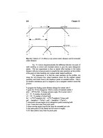
Mechanical Design
of
Pressure
Vessels
339
Figure
12-3.
Vessel
support devices.
(text
continued
from
page
335)
The
shell
weight
can be
estimated from:
where
W =
weight,
Ib
d
= ID, in.
t
=
wall thickness,
in.
L =
shell length,
ft
The
weight
of one
2:1
ellipsoidal
head
is
approximately:
The
weight
of a
cone
is:
a = one
half
the
cone apex angle
340
Design
of
GAS-HANDLING
Systems
and
Facilities
The
weight
of
nozzles
and
internals
can be
estimated
at 5 to 10% of
the
sum
of the
shell
and
head
weights.
The
weight
of a
skirt
can be
estimated
as the
same weight
per
foot
as the
shell
with
a
length given
by
Equation
12-8
for an
ellipsoidal
head
and
Equation
12-9
for a
conical head.
where
L =
skirt length,
ft
The
weight
of
pedestals
for a
horizontal vessel
can be
estimated
as 10%
of
the
total weight
of the
vessel.
SPECIFICATION
AND
DESIGN
OF
PRESSURE VESSELS
Pressure Vessel
Specifications
Most companies have
a
detailed general specification
for the
construc-
tion
of
pressure
vessels,
which defines
the
overall quality
of
fabrication
required
and
addresses specific items such
as:
»Code
compliance
•
Design conditions
and
materials
•
Design details
-
Vessel
design
and
tolerances
-
Vessel
connections (nozzle schedules)
-
Vessel
internals
-
Ladders, cages, platforms,
and
stairs
-
Vessel supports
and
lifting
lugs
-
Insulation supports
-
Shop drawings
•
Fabrication
-
General
-
Welding
-
Painting
-
Inspection
and
testing
-
Identification stamping
Mechanical
Design
of
Pressure
Vessels
341
-
Drawings,
final
reports,
and
data sheets
-
Preparation
for
shipment
A
copy
of
this specification
is
normally attached
to a bid
request
form,
which
includes
a
pressure vessel specification sheet such
as the one
shown
in
Figure
12-4.
This
sheet
contains schematic
vessel
drawings
and
pertinent
specifications
and
thus
defines
the
vessel
in
enough detail
so
the
manufacturer
can
quote
a
price
and so the
operator
can be
sure
that
all
quotes represent comparable quality.
The
vessel connections
(nozzle
schedules)
are
developed
from
mechanical
flow
diagrams.
It is not
neces-
sary
for the
bidder
to
know
the
location
of the
nozzles
to
submit
a
quote
or
even
to
order material.
Shop
Drawings
Before
the
vessel fabrication
can
proceed,
the
fabricator will develop
complete drawings
and
have these drawings
approved
by
the
representa-
tive
of the
engineering
firm
and/or
the
operating company.
These
draw-
ings
are
called shop drawings. They
will
show
detailed
vessel
design
and
fabrication/welding,
nozzle schedules
and
locations, details
of
vessel
internals,
and
other accessories. Examples
are
shown
in
Figures
12-5
through
12-13.
Some typical details
are
discussed below.
Nozzles
Nozzles
should
be
sized according
to
pipe sizing criteria, such
as
those
provided
in API RP
14E.
The
outlet nozzle
is
generally
the
same
size
as
the
inlet nozzle.
To
prevent
baffle
destruction
due to
impingement,
the
entering
fluid
velocity
is to be
limited
as:
where
V
]N
=
maximum inlet nozzle
fluid
velocity,
ft/sec
pi
=
density
of the
entering
fluid,
lb/ft
3
If
an
interior centrifugal (cyclone) separator
is
used,
the
inlet nozzle
size
should
be
the
same size
as the
pipe.
If the
internal design requires
(text
continued
on
page 346)
Figure
12-4,
Example
of
pressure
vessel
specification
sheet.
Figure
12-5,
Example
of
pressure
vessel
shop
drawing.
344
Design
of
GAS-HANDLING
Systems
and
Facilities
Figure
12-6.
Nozzle
projections.
(Reprinted
with
permission
from
Pressure
Vesset
Handbook,
Publishing,
Inc.,
Tulsa.)
Figure
12-7.
Siphon
drain.
Mechanical Design
of
Pressure
Vessels
345
Figure
12*8.
Example
of
supports
for
mist
extractors.
(Reprinted with permission
from
Pressure Vessel
Handbook,
Publishing,
Inc.,
Tulsa.)
Figure
12-9.
Examples
of
Vortex Breaker Details.
(Source:
Copyright
©
International
Training
&
Development.)
346
Design
of
GAS-HANDLING
Systems
and
Facilities
(text
continued
from
page
341)
the
smallest inlet
and
exit pressure losses possible,
the
nozzle size
shoulcf
be
increased.
Vortex
Breaker
As
liquid
flows
out of the
exit
nozzle,
it
will swirl
and
create
a
vortex.
Vortexing
would carry
the gas out
with
the
liquid. Therefore,
all
liquid
outlet
nozzles should
be
equipped
with
a
vortex breaker. Figure 12-9
shows
several vortex breaker designs. Additional designs
can be
found
in
the
Pressure
Vessel
Handbook.
Most designs depend
on
baffles
around
or
above
the
outlet
to
prevent swirling.
Manways
Manways
are
large openings that allow personnel
access
to the
vessel
internals
for
their maintenance
and/or
replacement. Vessels
36 in. and
larger
should have
a
minimum
of one
18-in.
manway. Vessels
30 in. and
smaller should have
two
4-in. flanged inspection openings. Manway
cover
davit should
be
provided
for
12-in.
and
larger manways
for
safe
and
easy
opening
and
closing
of the
cover. Figure
12-10
shows
an
exam-
ple
of a
horizontal manway cover davit
and
sleeve details.
Vessel
Supports
Small
vertical vessels
may be
supported
by
angle support legs,
as
shown
in
Figure
12-11.
Larger vertical vessels
are
generally supported
by
a
skirt support,
as
shown
in
Figure
12-12.
At
least
two (2)
vent holes,
180°
apart, should
be
provided
at the
uppermost
location
in the
skirt
to
prevent
the
accumulation
of
gas, which
may
create explosive conditions. Horizon-
tal
vessels
are
generally supported
by a
pair
of
saddle type supports.
Ladder
and
Platform
Ladder
and
platform should
be
provided
if
operators
are
required
to
climb
up to the top of the
vessel regularly.
An
example
is
shown
in
Fig-
ure
12-1.3.
Mechanical
Design
of
Pressure Vessels
347
Figure Figure
12-10.
Example
of
horizontal manway
cover
davit
and
sleeve
detail.
348
Design
of
GAS-HANDLING
Systems
and
Facilities
BASE
PLATE
SCHEDULE
ANGLE
LEG
SIZE
6*
x 6*
5" x 5"
4" x 4"
3" x 3"
2
1/2"
x 2
1/2"
"A"
a*
7*
6"
5*
4*
*&"
3
3/8"
2
7/8*
2*
1
3/4"
1
1/2"
ELEVATION
VIEW
Figure
12-11.
Angle
support
legs.
Pressure
Relief Devices
All
pressure vessels should
be
equipped with
one or
more pressure
safety
valves (PSVs)
to
prevent overpressure. This
is a
requirement
of
both
the
ASME
Code
and API RP 14C
(refer
to
Chapter
14).
The PSV
should
be
located upstream
of the
mist extractor.
If the PSV is
located
downstream
of the
mist extractor,
an
overpressure situation could occur
when
the
mist extractor becomes plugged isolating
the PSV
from
the
high
pressure,
or the
mist extractor could
be
damaged when
the
relief
Mechanical
Design
of
Pressure
Vessels
349
VENT
HOLES
In
service
of
hydrocarbons
or
other
combustible
liquids
or
gases
the
skirts
shall
be
provided with
minimum
of two 2
inch
vent
holes
located
as
high
as
possible
180
degrees
apart.
The
vent
holes
shall
clear
head insulation.
For
sleeve
may
be
used
coupling
or
pipe.
ACCESS
OPENINGS
The
shape
of
access
openings
may
be
circular
or any
other
shapes.
Circular
access
openings
are
used
most
frequently
with pipe
or
bent
plate
sleeves.
The
projection
of
sleeve
equals
to the
thickness
of
fireproofing
or
minimum
2
inches.
The
projection
of
sleeves
shall
be
increased when necessary
for
reinforcing
the
skirt
under certain
loading conditions.
Diameter
(0) =
16-24
inches
PIPE
OPENINGS
The
shape
of
pipe
openings
are
circular
with
a
diameter
of 1
inch
larger than
the
diameter
of
flange.
Sleeves
should
be
provided
as tor
access
openings.
Figure
12-12.
Skirt openings.
(Reprinted
with
permission
from
Pressure
Vessel
Handbook,
Publishing,
Inc.,
Tulsa.)
valve
opens, Rupture discs
are
sometimes
used
as a
backup
relief
device
for
the
PSV.
The
disc
is
designed
to
break when
the
internal pressure
exceeds
the set
point. Unlike
the
PSV, which
is
self-closing,
the
rupture
disc must
be
replaced
if it has
been activated.
Corrosion
Protection
Pressure vessels handling salt water
and fluids
containing
signficiant
amounts
of
H
2
S
and
CO
2
require corrosion protection. Common
corro-
350
Design
of
GAS-HANDLING
Systems
and
Facilities
SIDE
STEP THROUGH STEP
Figure
12*13.
Ladders.
(Reprinted with permission
from
Pressure
Vessel
Handbook,
Publishing,
Inc.,
Tulsa.)
sion
protection methods include internal coatings with synthetic poly-
meric materials
and
galvanic (sacrificial) anodes.
All
pressure
vessels
that
handle corrosive fluids should
be
monitored periodically. Ultrasonic
surveys
can
locate discontinuities
in the
metal structure, which will indi-
cate corrosion damages.
Mechanical Design
of
Pressure
Vessels
351
EXAMPLE
PROBLEM
12-1
Determine
the
weight
for the
following free-water knockout.
It is
butt
weld fabricated with spot x-ray
and to be
built
to
Division
1.
A
conical
head
(bottom
of the
vessel)
is
desired
for
ease
in
sand removal. Compare
this weight
to
that
of a
vessel without
the
conical section
and
that
to a
vessel with
a
!4-in.
plate internal cone.
Design pressure
=
125
psig
Maximum
operating temperature
=
200°F
Corrosion allowance
=
M
in.
Material
=
SA516
Grade
70
Diameter
=
1.0ft
Seam-to-seam length
above
the
cone
=12
ft
Cone
apex angle
= 60°
Solution:
Case
I—Cone
bottom
Required
thickness
=
0.507
+
0.250
=
0.757
in.
352
Design
of
GAS-HANDLING
Systems
and
Facilities
(b)Head:
(125)
(120)
|-
==
,
_
,—
=
y
505 in
(2)
(17,500) (0.85)
-
(0.2) (125)
Required
thickness
=
0.505
+
0.250
=
0.755
in.
Use—-in.
head (0.8125)
W
=
(0.34)(0.8125)(120)
2
+
(1.9)(0.8125)(120)
=
4,1631b
(c)
Cone:
_
Pd
~
2
cos
a
(SE
-
0.6P)
t
(125) (120)
t
=
•
=
0.585
in.
(2
cos 30)
(17,500
x
0.85
- 0.6 x
125)
Required
thickness
=
0.585
+
0.250
=
0.835
in.
Use in.
plate (0.875)
w
=
(0.23)
(0.875X120)1
=
sin
30
(d)
Skirt:
Height
=
——
=
8.66
ft
tan
30
Allow
2 ft for
access
Height
=11
ft.
Assume
it is
M-in.
plate.
W
=
(11X120X0.5X11)
=
7,260
(e)
Summary: Shell 12,870
Head
4,163
Cone 5,796
Skirt
7,260
30,089
Misc
5.000
35,089
Ib
Mechanical
Design
of
Pressure
Vessels
353
Case
II—Ellipsoidal
head
(a)
Skirt:
I-°^d
+
2
j_j
—
"
r
jL
12
_
(0.25) (120)
|
12
=
4.50
ft
W
=
(11)
(120) (0.5) (4.5)
=
2,970
Ib
(
b
)^EL
n
!
a
iy
:
Shdl
12
<
870
Head
4,163
Head
4,163
Skirt
2,970
24,166
Misc.
5,000
29,1661b
Case
III—Internal
cone
(a)
Internal Cone:
w
=
(0.23)
(0.25)
(120)
2
lb
sin
30
(b)
Shell:
Height
of
cone
=
= 8.7 ft
tan
30
Length
of
shell
=
12 + 8.7 =
20.7
ft
Weight
of
shell
=
(11)(120)(0.8125)(20.7)
=
22,200
Ib
354
Design
of
GAS-HANDLING
Systems
and
Facilities
(c)
Summary: Shell 22,200
Head
4,163
Head
4,163
Skirt
2,970
Cone
__L656
35,152
Misc.
_5JQQ
40,152
Ib
CHAPTER
13
Pressure
Relief*
The
most important
safety
devices
in a
production facility
are the
pres-
sure
relief valves, which ensure that pipes, valves, fittings,
and
pressure
vessels
can
never
be
subjected
to
pressures higher than their design pres-
sures. Relief valves must
be
designed
to
open rapidly
and
fully,
and be
adequately sized
to
handle
the
total
flow
of gas and
liquids that could
potentially cause
an
overpressure situation. They relieve
the
pressure
by
routing this stream
to a
safe
location where
it can be
vented
to
atmos-
phere
or
burned.
As
long
as
pressure, level,
and
temperature control devices
are
operat-
ing
correctly,
the
safety system
is not
needed.
If the
control system mal-
functions,
then pressure, level,
and
temperature
safety
switches sense
the
problem
so the
inflow
can be
shut
off.
If the
control system
fails
and
the
safety
switches
don't
work, then
relief
valves
are
needed
to
protect
against overpressure. Relief valves
are
essential because
safety
switches
do
fail
or can be
bypassed
for
operational reasons. Also, even when
safe-
ty
switches
operate
correctly, shutdown valves take time
to
operate,
and
there
may be
pressure stored
in
upstream vessels that
can
overpressure
downstream equipment while
the
system
is
shutting down. Relief valves
are an
essential element
in the
facility
safety
system.
*Reviewed
for the
1999
edition
by
Mary
E.
Thro
of
Paragon Engineering Services, Inc.
355
356
Design
of
GAS-HANDLING
Systems
and
Facilities
RELIEF
REQUIREMENTS
The
ASME
code
requires every pressure vessel that
can be
blocked
In
to
have
a
relief valve
to
alleviate pressure build
up due to
thermal expan-
sion
of
trapped gases
or
liquids.
In
addition,
the
American Petroleum
Institute
Recommended Practice
(API
RP)
14C,
"Analysis, Design,
Installation
and
Testing
of
Basic Surface Safety Systems
on
Offshore
Production
Platforms," recommends
that
relief valves
be
installed
at
vari-
ous
locations
in the
production system;
and
API
RP
520,
"Design
and
Installation
of
Pressure Relieving Systems
in
Refineries," recommends
various
conditions
for
sizing relief valves.
In
production facility design,
the
most common relieving conditions
are
(I)
blocked discharge,
(2) gas
blowby,
(3)
regulator failure,
(4)
fire,
(5)
thermal,
and (6)
heat exchanger tube rupture. Relief valve design
flow
rates
are
commonly determined
as
follows.
1.
Blocked Discharge.
It is
assumed that
all
outlets
from
the
vessel
are
shut
in and the total
inlet
flow
stream
(gas
and
liquids) must
flow
out
through
the
relief valve. This condition
could
occur,
for
exam-
ple,
if the
equipment
has
been shut
in and
isolated
and the
operator
opens
the
inlet before opening
the
outlet valves.
2.
Gas
Blowby.
A gas
blowby condition
is the
most critical
and
some-
times overlooked condition
in
production facility design.
It
assumes
that
there
is a
failure
of an
upstream control valve feeding
the
pres-
sure vessel
and
that
the
relief valve must handle
the
maximum
gas
flow
rate
into
the
system during this upset condition.
For
example,
if
the
liquid control valve
on a
high pressure
separator
were
to
fail
open,
all the
liquid would dump
to the
downstream lower-pressure
vessel.
Then
the gas
from
the
high pressure separator would start
to
flow to the
downstream vessel.
The
lower pressure
vessel's
relief
valve
must
be
sized
to
handle
the
total
gas flow
rate that will
fit
through
the
liquid dump valve
in a
full
open position.
We
normally
assume (conservatively) that
the
upstream
vessel
pressure
is the
PSV
set
point
(or
less
conservatively
at its
operating pressure)
and
the
downstream vessel
is at its PSV set
point.
The
resulting
gas
flow
rate
may be
larger than
the
design
gas flow
rate
to the
high-pressure
separator inlet.
The
rate
can be
reduced
by a
choke
or
other restric-
tions
in the
line.
In
that
case,
the
rate would
be the
maximum rate
that
would
fit
through
the
choke
at the
appropriate vessel pressures,
Most
accidents involving
overpressuring
of low
pressure separators
Pressure
Relief
357
are a
result
of
relief valves
not
being adequately sized
to
handle
the
gas
blowby
condition.
Note:
Liquid dump valves
are
normally
fail
closed
to
prevent
gas
blowby.
That means that
in
case
of
loss
of
instrument
gas or air
pressure,
the
spring
will
drive
the
valve
to the
closed
position. How-
ever,
the
valve
can
mechanically
fail
because
the
level controller
malfunctions
or the
seat cuts
out due to
solids erosion, which
would
cause
it to
fail
in an
open configuration.
3.
Regulator Failure.
It is
assumed that
a
pressure control valve
or
reg-
ulator
fails
in the
full
open position.
Regulator
failure
could occur
where
a
regulator
is
used
to
feed
gas from a
high pressure line
to a
fuel
gas
scrubber. Normally,
the
regulator
only
opens enough
to
keep
the
pressure
in the
scrubber constant.
If the
valve
fails
open,
the
users
can't
take
the
excess
gas,
so the
pressure
in the
scrubber
goes
up
until
the
relief valve opens.
The
feed
to the
regulator
is
assumed
to
be
(conservatively)
at the
upstream relief valve
set
point,
and the
downstream vessel will pressurize
to its
relief valve
set
point.
4.
Fire,
The
relief valve must
be
sized
to
handle
the
gases evolving
from
liquids
if the
equipment
is
exposed
to an
external
fire. A
proce-
dure
for
calculating this
is
presented
in API
RP
520. This condition
may
be
critical
for
large, low-pressure vessels
and
tanks
but
does
not
normally govern
for
other pressure vessels.
5.
Thermal
Thermal relief
is
needed
in a
vessel
or
piping
run
that
is
liquid-packed
and can be
isolated,
for
example
pig
launchers
and
meter provers. Liquid
is
subject
to
thermal expansion
if it is
heated.
It
is
also
incompressible.
The
thermal expansion
due to
heating
by
the
sun
from
a
nighttime temperature
of
80°F
to a
sun-heated
tem-
perature
of
120°F
can be
enough
to
rupture piping
or a
vessel.
The
required
capacity
of
thermal relief valves
is
very small.
6.
Tube
Rupture.
It is
common
for a
heat exhanger
to
have
a
high-pres-
sure
fluid in the
tubes
and a
lower-pressure
rated
shell.
If
there
is a
break
in one of the
tubes,
the
higher pressure
fluid
will leak
to the
shell,
resulting
in
overpressure.
It is
conservative
to
assume
a
tube
is
completely split with choked
flow
from
both sides
of the
break.
A
vessel
may be
subject
to
more than
one
condition under
different
failure
scenarios.
For
example,
a low
pressure
separator
may be
subject
to
blocked discharge,
gas
blowby
from
the
high pressure separator,
and
fire.
Only
one of
these failures
is
assumed
to
happen
at any
time.
The
relief
valve
size
needs
to be
calculated
for
each pertinent relieving rate
358
Design
of
GAS-HANDLING
Systems
and
Facilities
Table
13-1
Maximum
Rale
Relieving
Scenarios
Vessel
Relieving
Scenarios
Production
Separators
Blocked
Discharge
Test
Separators Blocked Discharge
Low
Pressure
Separators
Blocked Discharge
or
Blowby
Glycol Contact Tower Fire
Oil
Treater
Gas
Blowby
or
Fire
Utility
or
Fuel
Gas
Scrubber Regulator Failure
Heat Exchanger Tube
Rupture
Compressor Scrubber Fire
Compressor
Discharge Blocked Discharge
and
the
largest size used.
The
usual controlling cases
for
common vessels
and
piping
are
shown
in
Table
13-1.
A
vessel
can
only
be
overpressured
if the
upstream vessel
has a
higher
pressure
than
the
vessel
in
question.
A
compressor scrubber with
a
MAWP
of 285
that gets
flow
from
a 285
MAWP separator does
not
need
to
have
a
relief valve sized
for
blocked discharge.
The
upstream relief
valve
will keep
the
upstream separator pressure
from
going higher than
285,
so
there
is no way it can
overpressure
the
downstream scrubber.
The
scrubber
PSV
only needs
to be
sized
for fire.
The
same concept applies
to a
glycol contact tower, except
for
one
small
trick. Contact towers
often
handle glycol
at
temperatures above
1QO°F,
so the
MAWP
is
reduced
for the
higher temperature
(e.g.
1,440
psig
at
130°F
rather than 1,480 psig
at
100°F).
In
order
to
keep
from
siz-
ing
the
contact tower relief valve
for the
full
wellstream
gas flow, the
sep-
arator relief valve
is
usually
set at the
glycol tower MAWP
(1,440
psig)
even
though
the
separator MAWP
may
actually
be
higher
(1,480
psig).
Good
engineering judgment should
be
used
to
determine
the
relief rate
when
the
separator MAWP
is
higher than
the
well
SITP.
Unexpected
things
can
happen with
a
well. Production reservoirs
at
different
pres-
sures
within
the
well bore
can
communicate
in
unexpected ways (for
example,
as the
result
of a
poor
cement
job). Where
flow is
coming
from
a
well,
it is a
good idea
to
provide
an
extra margin
of
safety.
If the
vessel
MAWP
is not
significantly higher than
the
well SITP,
the
relief valve
should
be
sized
for
blocked discharge
of the
full
production rate.
Figure
13-1
shows
the
various relationships between MAWP
and the
relief valve
set
pressure.
The
primary relief valve should
be set to
open
at
no
more
than
100%
of
MAWP
and to
relieve
the
worst case
flow
rates,
Pressure
Relief
359
NOTES:
1.
Tile
operating
pm*u»
may
be any tower
pressure
required.
2.
The
set
presaure
ami
all
other
values
related
to it may be
moved
dcwnwd
if
ibe
operating
pressure
permits.
3.
this
figure
conforms
with
the
requirements
at
the
ASME
Boiltr
aid
Pnaurt
Vtatl
Code,
Section
VIII,
"Pressure
Vessels,"
Division
I.
4.
The
pressure
condition
shown
are for
safety
relief
valves
installed
on a
pressure
vessel
(vapor
phase).
Figure
13-1.
Various
relationships
between
MAWPs
and
relief
valve
set
pressure.
I
Reprinted
wirfi
permission
from
API RP
521.}
not
counting
fire
(i.e., blocked discharge
or gas
blowby),
at a
pressure
of
1.10
MAWP.
If two
relief valves
are
used
to
handle
the
worst case
flow
rates,
the first
must
be set no
higher than 100% MAWP
and the
second
at
1.05 MAWP. They must relieve
the
worst case
flow
rates,
not
counting
fire,
at
1.16
MAWP.
The
maximum pressure
for
relieving
fire
relief rates
360
Design
of
GAS-HANDLING
Systems
and
Facilities
is
1.21 MAWP. Thus, under relief conditions,
the
pressure
in the
vessel
may
actually exceed MAWP. This buildup
of
pressure
in the
vessel above
the
MAWP
as the
relief valve opens
is
called
"overpressure."
This
is
taken
into account
by the
various
safety
factors
in the
ASME Code
and is
one of the
reasons
the
vessel
is
originally tested
to
1.5
MAWP.
The
relief valve must
be
installed
so
that gases
are
routed
to a
safe
location.
In
small facilities
and
remote locations this
is
accomplished
with
a
simple
"tail
pipe,"
which points
the
discharge vertically upward
and
creates
a jet in
excess
of 500
feet
per
second.
The jet
action dilutes
the
discharge gases
to
below
the
lower flammable limit
in
approximately
120
pipe diameters. Liquids
may
fall
back
on the
equipment.
In
large facilities
and
offshore platforms where
the
escaping gases
and
liquids
could present
a
source
of
pollution
or
ignition,
it is
common
to
route
the
relief valve discharges
into
a
common
"header"
that discharges
at
a
remote safe location. Often
a
vent scrubber
is
installed
in
this header
to
separate
the
bulk
of the
liquids
and to
minimize
the
possibility
of
liq-
uid
discharges
to
atmosphere.
TYPE
OF
DEVICES
Valves
that activate automatically
to
relieve pressure
are
called "safety
valves,"
"relief
valves,"
or
"safety relief
valves."
Safety valves
are
spring
loaded
and
characterized
by a
rapid
full
opening
or
"pop" action. They
are
used primarily
for
steam
or air
service. Sometimes they
are
referred
to
as
"pop
valves."
Relief valves
are
spring loaded
and
open more slow-
ly.
They reach
full
opening
at 25%
over
set
pressure
and are
used primar-
ily
for
liquid services. Safety relief valves
can be
either spring loaded
or
pilot operated
and are
designed
to
provide
full
opening with little over-
pressure. Most automatically-actuating
relief
devices used
in
production
facilities
are
actually safety relief valves; however, they
are
commonly
referred
to as
relief valves
or
safety valves.
In
this
book
the
term
"relief
valve"
is
used
in the
generic sense
of any
automatically-actuating
pres-
sure
relieving device.
There
are
three types
of
relief valves: conventional, balanced-bellows,
and
spring loaded.
Conventional
Relief
Valves
Figure 13-2 shows
a
cross
section
of a
conventional
relief
valve
and
Figure
13-3
is a
schematic that shows
the
valve's operation. Convention-