ARNOLD, K. (1999). Design of Gas-Handling Systems and Facilities (2nd ed.) Episode 2 Part 11 ppsx
Bạn đang xem bản rút gọn của tài liệu. Xem và tải ngay bản đầy đủ của tài liệu tại đây (1.32 MB, 25 trang )
486
Design
of
GAS-HANDLING
Systems
and
Facilities
low
as
possible,
it may be
necessary
to
unload
the
driven equipment dur-
ing
start-up.
Figure
16-16
shows
the
performance
characteristic
of a
split-shaft
tur-
bine
where
the
only power output limitation
is the
maximum allowable
temperature
at the
inlet
of the
turbine section.
In
actual practice
a torque
limit,
increased exhaust
temperature,
loss
of
turbine
efficiency,
and/or
a
lubrication
problem
on the
driven equipment usually preclude operating
at
very
low
power
turbine
speeds.
The
useful
characteristic
of the
split-shaft
engine
is its
ability
to
supply
a
more
or
less constant horsepower
output
over
a
wide range
of
power turbine
speeds.
The air
compressor essentially
sets
a
power level
and the
output
shaft
attains
a
speed
to
provide
the
required
torque balance. Compressors, pumps,
and
various
mechanical
drive
systems make very good applications
for
split-shaft
designs.
Effect
of Air
Contaminants
The
best overall
efficiency
of a
turbine
can be
ensured
by
maintaining
the
efficiency
of the air
compressor
section.
Conversely,
allowing
the air
compressor efficiency
to
deteriorate will
deteriorate
the
overall thermal
efficiency
of the
turbine.
Air
compressor
efficiency
can be
drastically
reduced
in a
very short time when dirt, salt water mist,
or
similar
air
con-
Figure
16-16.
Performance
characteristics
of a
multi-shaft
turbine.
Prime
Movers
487
taminants
enter
the
inlet air. Contaminants will accumulate
in the air
compressor
and
reduce
its
compression efficiency.
The
effect
will
be
decreased mass
flow,
reduced compressor discharge pressure, reduced
horsepower,
and
higher-than-normal
engine temperatures.
Effective
inlet
air filtration is
required
to
ensure satisfactory operation
of
the
engine.
The
location
of the
unit
determines
the
most appropriate
filter
system
to
use. Desert environments where
a
large amount
of
sand
particles could
be
expected
in the
ambient
air may use an
automatic
roll
type
of
filter that allows
new filter
material
to be
rolled
in
front
of
the
inlet
without frequent shut-downs
to
change filters. Arctic
or
extremely
cold
locations
may use pad
type filters, snow hoods
to
prevent blockage,
and
exhaust
recirculation
to
prevent icing. Filter assemblies
for
offshore
marine environments
may
include weather louvers,
demister
pads,
and
barrier elements
for
salt
and
dirt removal. Screens
may be
used
for
insect
removal
prior
to filtration in
areas with
bug
problems.
Cleaning
the air
compressor
can be
accomplished
by
injecting water,
steam,
detergent,
and/or
abrasive material
(such
as
walnut hulls) into
the
air
inlet. Engine
life
and
performance
will
be
improved
if
cleaning
is
done
on
a
periodic basis
so as to
keep
any
hard deposits
of
oil, dirt, etc.
from
forming.
In
general,
frequent
detergent washing will ensure compressor
cleanliness.
Steam cleaning with
an
appropriate detergent
is
also very
effective.
Abrasive cleaning should
be
avoided
and
only
be
necessary
as
the
result
of
improper
frequency
or
technique
of
detergent washing.
ENVIRONMENTAL
CONSIDERATIONS
Air
Pollution
Exhaust
emissions will vary with
the
type
and
age of
engine
and the
fuel
used. Current environmental regulations must
be
consulted.
It may
be
necessary
to
submit
a
permit
to
install
the new
equipment. Each coun-
try,
state,
or
county
has
variations
of the
maximum emissions.
In
general, liquid fueled engines tend
to
have
increased
emission lev-
els of
particulates
and
unburned
hydrocarbons
over
those
of
gaseous
fueled
engines.
Due to the
large quantities
of
excess air,
gas
turbines tend
to
have lower emission levels
of
particulates
and
unburned hydrocarbons
than
reciprocating engines.
Gas
turbines
do,
however, tend
to
produce
greater quantities
of
nitrogen
oxides
(NO
X
).
The
formation
of
NO
X
depends
on
combustion temperature
and
residence
times
at
high tempera-
tures,
both
of
which
are
higher
in gas
turbines than
in
engines. Engines,
488
Design
of
GAS-HANDLING
Systems
and
Facilities
on
the
other hand, tend
to
have greater concentrations
of
carbon
monox-
ide,
CO, in
their exhausts.
Fuel
quality will greatly
affect
emissions
and can
also
have consider-
able
effect
on
engine life. Manufacturers' specifications
will
generally
specify
fuel
quality
for
proper operation.
In
addition
to
carbon monoxide
(CO)
and
unburned
hydrocarbons
(UHC),
the
most significant products
of
combustion
are the
oxides
of
nitrogen
(NO
X
).
At
high temperatures,
free
oxygen
not
consumed during
combustion
reacts
with nitrogen
to
form
NO and
NO
2
(about
90% and
10%
of
total
NO
X
,
respectively).
Improvements
in
engine
and
turbine design, along with
the use of
aux-
iliary
equipment such
as
catalytic converters,
selective
catalytic reduc-
tion (SCR) units
and the use of
steam
and
water injection into turbines,
combine
to
reduce overall emission
levels.
When
a
hydrocarbon
fuel
such
as
natural
gas is
burned
in an
engine
or
turbine,
the
concentration
of
pollutants
is
dependent
on the air to
fuel
(A/F)
ratio
as
shown
in
Figure
16-17.
If
pollution
was not a
concern,
in
order
to
obtain maximum
thermodynamic
efficiency,
the
engine
would
be
designed
for a
slightly greater than
stoichiometric
mixture. Because
air and
fuel
are
never perfectly mixed
at the
time
of
ignition, excess
air
must
be
present
to
burn
all the
fuel.
The
normal amount
of
excess
air
that
achieves this efficiency
is
around
15-20%.
Under these conditions,
Fig-
ure
16-17
shows that
a
relatively large amount
of
NO
X
will
be
formed.
NO
X
emission controls
in
large engines
and
turbines
are
based
on the
same principles. However, special designs must
be
applied
to
accommo-
date differences
in the
combustion process. Methods
to
control
NO
X
include
the
following.
NO
X
Reduction
in
Engines
1.
Lean
Burn
As
shown
in
Figure
16-17,
at
very high
A/F
ratios—greater
than
30:1—
the
production
of
NO
X
can be
very
low.
The
problem with
simply
increasing
A/F
ratio
is
that,
because
the
air/fuel
mix is not
uniform,
increasing
A/F
ratio
in the
cylinder increases
the
probabili-
ty
that
the
mixture
at the
point
of the
spark plug
may be too
lean,
thus
leading
to a
misfire.
Installing
a
pre-combustion
chamber (PCC)
in the
engine design
solves
this problem.
In
this design,
a
normal
A/F
ratio
fuel
is
intro-
duced
into
a PCC at the
time
of
ignition. This
creates
ignition
torch-
Prime
Movers
489
Figure
16-17.
Emission trends
vs. A/F
ratio
for a typical
engine/turbine.
es
that enter
the
main cylinder, which
has the
lean
A/F
ratio,
and
ignites
the
fuel.
2.
Catalytic
Converter
Catalytic converters
are
designed
to
oxidize
the
unburned
UHCs
and
CO. The
resulting combustion (oxidation) converts them into
490
Design
of
GAS-HANDLING
Systems
and
Facilities
water
and
CO
2
.
A
recent catalytic converter design called three-way
converters also controls
NO
X
using
a
reduction process. Three-way
converters
contain
two
catalytic "bricks,"
one for
reduction
and
the
other
one for
oxidation.
The
oxidation process
with
CO
takes place
as;
2CO +
O
2
<-»
2CO
2
The
oxidation
of UHC is:
2O
2
+
CH
4
<-»
CO
2
+
2H
2
O
And
finally,
the
reduction
of
NO
X
with
CO
results
in
N
2
and
CO
2
:
NO
2
+ CO
<-»
NO +
CO
2
2NO + 2CO
<-»
N
2
+
2CO
2
Catalytic reactions occur when
the
temperature exceeds
500°~6QO°F
(260°-316°C).
Normal converter operating temperatures
are
9QO°-1200°F
(482°-649°C).
Excessively rich
A/F
ratio causes converter operating tempera-
tures
to
rise dramatically, thus causing converter meltdown.
On the
other
hand,
if the
A/F
ratio
is too
lean,
the
excess
O
2
will react with
the
CO, and the
reduction
of
nitrogen with
CO
will
not
take place.
Thus,
catalytic converters cannot
be
used where there
is
excess air.
3.
Selective Catalytic Reduction (SCR)
Selective catalytic reduction
is
based
on
selective reactions
of a
continuous
gaseous
flow
of
ammonia
or
similar reducing agents
with
the
exhaust
stream
in the
presence
of a
catalyst.
The
reaction
that
occurs
is as
follows:
4NH
3
+ 6NO
<-»
5N
2
+
6H
2
O
SCR
units require handling,
storage,
and
continuous injection
of
the
reducing agent.
The
temperature level
is
critical because
the
SCR
operates
in a
narrow temperature range between
550°~750°F
(260°-399°C),
and
thus
an
exchanger
is
necessary
to
cool
the
exhaust
stream. This leads
to a
complicated
and
costly process sys-
tem
that must
be
added
to the
engine exhaust.
Prime
Movers
491
NO
X
Reduction
in
Turbines
1,
Inject Steam
or
Water
This
system
is
called
wet
NO
X
control. Water
or
steam
is
injected
into
the
primary combustion zone. This method
has
been used
effec-
tively
in the
past. Current installations
are
using this system when
the
water
or
steam
is
readily available
or if
they
are
already part
of
the
process. Maintenance costs
are
higher when compared with
dry
control, because this method requires high quality water.
If
high
quality water
is not
used,
the
corrosion
associated
with dissolved
minerals
in the
water
may
prematurely damage
the
turbine.
2.
Lean
Premised
Combustion
When
air and
fuel
are
mixed
and
burned
in
standard turbine com-
bustion
systems, incomplete mixture occurs. Areas
of rich
A/F
ratios
exist, which cause local high temperatures called
"hot
spots."
Nor-
mal
turbine combustion temperatures
can
reach
2800°F
(1538°C).
Because
NO
X
formation rate
is an
exponential function
of
tempera-
ture,
decreasing
the
combustor temperature
can
substantially
reduce
NO
X
production.
One
method
of
reducing
hot
spots
is to
premix
a
lean
A/F
ratio prior
to
combustion. Lower
temperature
levels
are
achieved
by
using stages (multiple sets
of air and
fuel
injectors)
and
by
adding special instrumentation
to
control
the
appropriate
propor-
tion
of air and
fuel.
Excess
air is
used
to
further
reduce
the
overall
flame
temperature. Using this approach, most
gas
turbine
manufac-
turers
are
able
to
guarantee about
25
ppmv.
3.
Selective
Catalytic Reduction (SCR)
SCR
is
described above.
It is
important
to
note that SCRs require
a
lot of
space,
are
relatively expensive,
and use
toxic metals. There-
fore,
they
may not be
practical
and may be too
costly
to
install
and
operate compared with other methods.
4,
Catalytic Combustor
A
recent innovation includes
use of a
catalytic combustor. Several
tests with large turbines indicate that this alternative
can
reduce
NO
X
emission
to
less
than
5
ppmv.
The
catalyst inside
the
combustion
chamber actually causes
a
portion
of the
fuel
to
burn without
the
pres-
ence
of a flame.
This
significantly
reduces combustion temperature.
492
Design
of
GAS-HANDLING
Systems
and
Facilities
Based
on the
results
of the
catalytic
combustor,
there
is an
effort
under
way to
develop
this concept
into
a
practical,
field-proven
technology.
Noise
Pollution
Increased public awareness
of
noise
as an
environmental pollutant
and
as a
hazard
to the
hearing
of
personnel
requires
that attention
be
given
to
this
problem during
the
design phase. When
a
prime mover installation
is
planned, enough
silencing
should
be
installed
to
ensure that
the
noise
level
will
be
acceptable
to the
community
and
meets
all
governmental
requirements.
The
requirements will vary substantially depending upon
such
factors
as
location, population density, operating personnel
in the
area,
etc.
CHAPTER
17
Electrical
Systems*
This chapter introduces some concepts concerning electrical system
design
and
installation that
are
particularly important
from
the
standpoint
of
safety
and/or operational considerations
for
production facilities.
The
reader
is
referred
to
texts
in
electrical engineering
and to the
various
codes
and
standards listed
at the end of
this
chapter
for a
more detailed
description concerning
the
design
of
electrical circuits, sizing conductors,
and
circuit breakers, etc. This chapter
is
meant merely
as an
overview
of
this complex subject
so
that
the
project facilities engineer will
be
able
to
communicate
more
effectively
with electrical design engineers
and
ven-
dors
who are
responsible
for the
detail design
of the
electrical
system.
SOURCES
OF
POWER
The
required power
for
production facilities
is
either generated
on
site
by
engine-
or
turbine-driven generator units
or
purchased
from
a
local
utility
company.
For
onshore facilities
the
power
is
generally purchased
from
a
utility. However,
if the
facility
is at
a
remote
location
where there
*Reviewed
for the
1999 edition
by
Dinesh
P.
Patel
of
Paragon Engineering
Services,
Inc.
493
494
Design
of
GAS-HANDLING
Systems
and
Facilities
is
no
existing utility power distribution,
an
on-site
generating unit
may be
considered.
A
standby generator
may be
required
if
utility power
is not
sufficiently
reliable.
The
standby generator
may be
sized
to
handle either
the
total
facility
load
or
only essential loads during periods
of
utility
power
failure.
In
the
case
of an
offshore
facility,
electrical power
is
generally gener-
ated
on
site
by
engine-
or
turbine-driven generator sets using natural
gas
or
diesel
as
fuel.
Most installations
are
designed
to
handle
the
total
elec-
trical
load
even
if one
generator
is out of
service.
To
minimize
the
size
of
standby
equipment, some facilities have
a
system
to
automatically
shed
non-essential
loads
if one
generator
is out of
service.
Some offshore
facilities
are
furnished power
from
onshore
via
high-voltage cables.
The
cables
are
generally laid
on the
ocean
floor and are
buried
in
shallow
water.
In
some cases
a
single cable (usually three-phase)
is
used
for
such
applications
to
minimize initial project cost. However,
if a
fault
develops
in
this
single cable,
the
facility
could
be
shut
in for
extended periods
of
time.
To
avoid extended shut-ins, either
a
spare
or
alternate cable
can be
installed
or
standby generators
can be
installed
on the
offshore platform.
The
choice
of
whether
to
purchase
or
generate electricity
and
decisions
on
generator
or
cable
configuration
and
sparing
are
often
not
obvious.
An
economic study evaluating capital
and
operating costs
and
system
relia-
bility
of
several alternatives
may be
required.
Utility
Power
Utility
companies have
a
power system network including large gener-
ating
plants, overhead transmission lines, power substations which
reduce transmission line voltages
to
distribution line voltages,
and
over-
head/underground distribution lines which carry power
to the end
users
(such
as a
production facility).
The
power
from
the
distribution line voltage
is
converted
to
facility
distribution
voltage using
a
"step-down" transformer, providing power
to
facility
switchgear
and
motor control centers.
The
facility
distribution
voltage
selection depends upon
the
length
of the
distribution system,
the
size,
and
location
of the
electrical
loads
to be
served. Most
oil
field elec-
trical distribution systems
in the
United States
are
4,160
or
2,300
volts.
Typically,
480
volts
is
used
for
motor
and
other
three
phase
loads;
240/
120
volts usually
is
used
for
lighting
and
other single phase loads,
and
120
volts usually
is
used
for
control circuits. Step-down transformers
deliver
these voltages
from
the
facility
distribution system.
Electrical
Systems
495
The
electrical distribution system design
and
equipment
selection
must
consider
requirements
of the
utility
company
for
protection
and
metering.
Available
short circuit currents
from
the
utility
distribution network
to
the
primary
of the
facility's main transformer must
be
considered
in
selecting
circuit protection devices
for the
facility
distribution system,
Electrical
Generating
Stations
Where
electricity
is
generated
in the
facility,
generator
sizing
should
consider
not
only connected electrical
loads,
but
also
starting loads
and
anticipated
and
non-anticipated expansions.
In
most installations this
is
done
by
developing
an
electrical load list itemizing
the
various
loads
as
either continuous, standby
or
intermittent service. Examples
of
continu-
ous
loads
are
electric
lighting,
process
pumps
and
compressors required
to
handle
the
design
flow
conditions,
and
either quarters heating
or air
conditioning, whichever
is
larger. Intermittent loads would include quar-
ters kitchen equipment,
washdown
pumps, cranes,
air
compressors
and
similar
devices which
are not in use at the
same time.
The
total demand
is
normally taken
as
100%
of the
continuous
loads,
40 to 60% of the
intermittent
loads
and an
allowance
for
future
demand. Standby loads
do
not
add to
generator demand
as
they
are
activated only when another
load
is out of
service.
Generators
must
be
sized
to
handle
the
starting current associated
with
starting
the
largest motor.
On
large facilities with many small motors,
starting
current usually
can be
neglected unless
all the
motors
are
expect-
ed to
start simultaneously. However,
if the
total load
is
dominated
by
sev-
eral
large motors,
the
starting load must
be
considered.
In
calculating generator
loads
it
must
be
remembered that each motor
will
only
draw
the
load demanded
by the
process.
It is
this load
and not
the
nameplate
rating
of the
motor that should
be
used
in the
load list.
For
example, even though
a
pump
is
driven
by a 100 hp
motor,
if the
process
conditions
only demand
75 hp, the
total load that
will
be
demanded
from
the
generator
is 75 hp.
Generators
are
normally provided
with
static voltage regulators capa-
ble of
maintaining
1%
voltage regulation
from
no
load
to
full
load. While
random ("mush") wound stators
are
acceptable
for
smaller units, formed
coils
are
normally preferred
for
generators
of
approximately
150 kW or
larger.
Vacuum-pressure-impregnated
(VPI)
windings
are
recommended
for
all
units
operating
in
high-humidity
environments.
496
Design
of
GAS-HANDLING
Systems
and
Facilities
Smaller generators, typical
of
those frequently used
at
production
facilities,
often
cannot provide enough current
to
operate
the
instanta-
neous
trip
of
magnetic circuit breakers used
as
main circuit breakers
under
certain conditions. Manufacturers' data should
be
obtained
for
units
under consideration and,
if
necessary,
a
short-circuit boost option
or
a
permanent magnet rotor (PMG) option should
be
considered. These
options will assist
the
voltage regulator
in
delivering
full
exciter voltage
and
current during periods
of
severe generator overload
and
short circuit
conditions.
This helps assure
that
the
generators
are
capable
of
delivering
enough
current
to
trip
the
main circuit breaker.
When
generators
are
specified,
it
should
be
realized that both mechan-
ical
and
electrical requirements
differ
between units which
will
be
used
for
standby service
and
units which
will
be
operated continuously.
Typi-
cally, standby units have less copper
in
their windings than continuous
duty
units,
causing standby units
to
reach higher temperatures
if
operated
continuously,
and
thus reducing
life.
Standby units,
as
classified
by
most
manufacturers,
are not to be
confused with
units
which
are
alternated
weekly
(or on
some other regular
basis),
but
which
are
operated continu-
ously
when they
are "on
line." This operating mode
should
be
considered
""continuous
duty."
POWER SYSTEM
DESIGN
Three-Phase
Connections
Electrical power systems
are
normally three-phase systems
connected
using
"wye"
or
"delta"
connections.
In
"wye" connections
the
three
phases
are
connected
to
form
a
letter
"Y"
with
a
neutral point
at the
inter-
section
of the
three phases.
In
"delta"
connections
the
three phases
are
connected
to form a
Greek letter
"delta"
(A). Delta systems
do not
have
a
neutral; hence delta systems
are
3-wire systems.
A Y
connection
has a
neutral
and
thus
it is a
4-wire
system.
Generators typically
are
Y-connected
to
provide
three
phases
and a
neutral
for a
3-phase, 4-wire system.
The
neutral
can be
grounded
or
ungrounded,
but a
grounded neutral
is
usually preferred.
Transformers
can be
delta-connected
on
both
the
primary side
and the
secondary side
for a
3-phase, 3-wire system
or
delta
on the
primary side
and
Y on
secondary side
for a
3-phase, 4-wire system. Transformers
can
also
be
Y
connected
on
both primary
and
secondary sides,
but
such
is
not
Electrical
Systems
497
recommended unless special precautions
are
taken
to
accommodate
third
harmonic currents.
Figure
17-1
shows
a
typical system
with
a
Y-connected
generator,
a
delta-connected motor,
and a
transformer
with
a
delta-connected
primary
and
Y-connected secondary.
Power
Apparent power
is the
total power
of a
circuit
and is
measured
in VA
or
kVA
(1,000
VA).
It is
obtained
by
multiplying voltage
and
current.
Figure
17-1.
Three-phase
connections.
498
Design
of
GAS-HANDLING
Systems
and
Facilities
where
E =
line-to-line voltage,
volts
I
=
line current, amperes (amps)
"Active power"
is the
portion
of the
apparent power that
is
consumed
by
the
load
to
produce work.
It is
obtained
by
multiplying
the
current
through
a
load
by the
voltage across
the
load
and is
expressed
in
watts
or
kilowatts
(1,000
watts).
where
9 =
power factor angle, radians
or
degrees
"Reactive power"
is the
portion
of the
apparent power necessary
to
pro-
duce magnetic
flux
in
motors.
This
power
is not
transmitted
to the
load
to
produce real work.
It is
expressed
in VAR or
kVAR
(1,000
VAR).
Power
Factor
Power
factor
is the
ratio
of the
active power
to the
apparent power:
The
power factor indicates
the
portion
of
total power which
is
consumed
by
the
load.
The
power factor
is
"leading"
in
capacitive loads,
"lagging"
in
inductive loads,
and
"unity"
in
resistive loads. Figure 17-2 shows
"power
triangles"
to
illustrate power factor terms.
When
the
power factor
is
less than unity, there
is
reactive power pre-
sent.
In
other words, more power
is
required
to
produce
the
work than
is
absolutely
necessary. This translates into higher energy cost
and
larger
Electrical Systems
499
a)
LAGGING
POWER
FACTOR
b)
LEADING
POWER
FACTOR
c)
UNITY
POWER
FACTOR
Figure
17-2.
Power factor terms.
generating units
and
transformers. Also,
low
power factor
may
reduce
voltage,
causing motors
to
operate
in a
sluggish manner
or
lights
to
dim.
The
power
factor
can be
made
to
approach
unity
by
removing reactive
power
from
the
system. Lightly loaded induction motors
are
particularly
guilty
of
producing
low
power
factors
since
the
reactive power does
not
change with
the
load
on the
motor. This causes high phase angles
at low
load—creating
low
power factors.
By
keeping motors
at or
near
full
load,
system
power factors
can be
improved. Power factors
can
also
be
improved
by
using leading-power-factor synchronous motors
or
power
capacitors.
500
Design
of
GAS-HANDLING
Systems
and
Facilities
Short
Circuit
Currents
To
avoid damage
to
equipment
and
harm
to
personnel, electrical com-
ponents
of the
facility power system must
be
selected
to
withstand
avail-
able
short circuit currents
and to
isolate facility circuits quickly.
When
a
short circuit occurs, load impedance
no
longer limits current.
Only
the
power source capability
and
internal
impedance
limit
the
amount
of
short circuit current.
In a
facility powered
by
generators,
the
magnitude
of
these currents depends
on
generator capacity
and
internal
impedance
and the
number
of
units operating
at the
time
of the
short
cir-
cuit.
In a
facility powered
by a
utility
company (with large available
short circuit
currents),
the
internal
impedance
of the
facility's main trans-
former
and the
interconnecting
wiring
determines
the
magnitude
of
short
circuit
currents.
All
electrical protective equipment (e.g., circuit breakers,
fuses,
bus
bars,
and
motor starters)
is
rated
for
maximum short circuit currents
by
NEMA
standards. Proper selection
of
equipment must
be
based
on
avail-
able
short circuit currents.
HAZARDOUS
AREA
(LOCATION)
CLASSIFICATION
In
order
to
properly select
and
install electrical equipment
in a
location
which
contains,
or may
contain, flammable gases
or
vapors, combustible
dust,
or
easily ignitible fibers,
the
location must
first
be
"classified."
The
classification process
is
threefold:
first,
one
must designate
the
type
of
hazard
or
"class"
that
may be
present—gas,
dust,
or
fiber; second,
one
must
designate
the
specific
"group"
of the
hazardous substance;
third,
one
must determine
the
probability that
the
hazardous substance will
be
present.
Figure
17-3
is a
diagram showing
the
various
classes
and
groups
that
are
used
in the
U.S.
and
Canada.
In oil and gas
production
facility
design almost
all
classifications will
be
Class
I,
Group
D.
In
addition
to
being toxic, hydrogen
sulfide-air
mixtures
are flamma-
ble
in
concentrations
of
approximately
4.3%
to
45.5%
hydrogen sulfide
by
volume.
If air
containing more than
4.3%
hydrogen sulfide
is
possi-
ble,
Class
I,
Group
C,
electrical equipment must
be
installed,
although
specific
laboratory tests have
not
been performed
to
determine
the
per-
centage level
of
hydrogen sulfide
in a
hydrogen
sulfide-natural
gas
mix-
ture
at
which
the
mixture should
be
considered Group
C. API RP 500
Electrical Systems
501
Figure
17-3.
Hazardous
area
classifications
used
in
U.S.
and
Canada,
in
accordance
with Article 500,
NEC
Code—1984.
(Courtesy
of R.
Stahl,
Inc.]
502
Design
of
GAS-HANDLING
Systems
and
Facilities
Electrical
Systems
503
recommends
that mixtures containing
less
than
25%
hydrogen
sulfide
be
considered Group
D;
above this
level
they should
be
considered
Group
C.
Designating
the
"group"
of a
specific material
is
easily accomplished
by
referencing either
the
National Electrical Code
or the
National
Fire
Protection Association's documents numbered 325M
and
497M.
Deciding
the
probability that ignitible concentrations
of the
hazardous
substance
will
be
present
is the
most
difficult
of the
steps
in
classifying
an
area. Class
I and II
areas
are
referred
to as
Division
1
areas when
ignitible
concentrations
of
hazardous materials
are
anticipated during
normal
operations,
on a
continuous
or
intermittent basis. Areas
are
referred
to as
Division
2
areas when ignitible concentrations
are
antici-
pated
only
during abnormal operations. Additionally, areas
are
consid-
ered
Division
1 if a
process
failure
is
likely
to
cause ignitible levels
of
hazardous
material
and
cause
an
electrical
fault
in a
mode that could
result
in an
electrical arc. Also, Class
II
areas
are
considered Division
1 if
the
hazardous dust involved
is
metallic. Class
III
areas
are
specified
Division
1 if the
easily ignitible materials
are
handled, manufactured,
or
used,
and
Division
2 if
they
are
stored
or
handled
in a
non-manufacturing
environment.
Any
area which
is not
Division
1 or 2 is
termed "unclassi-
fied"
or
"non-hazardous."
The
European philosophy
on
area classification varies
from
that
of the
United
States
and
Canada. Specifically,
in
Europe
and
most other inter-
national areas,
the
"Zone"
concept
is
utilized.
An
area
in
which
an
explo-
sive
gas-air mixture
is
continuously present,
or
present
for
long periods
of
time,
is
referred
to as
Zone
0. The
vapor space
of a
closed,
but
vented,
process vessel
or
storage tank
is an
example.
An
area
in
which
an
explo-
sive
gas-air mixture
is
likely
to
occur
in
normal operations
is
designated
Zone
1. An
area
in
which
an
explosive gas-air mixture
is
less likely
to
occur,
and if it
does
occur will exist only
for a
short time,
is
designated
Zone
2.
Zone
0 and
Zone
1
correspond
to
Division
1 in the
U.S.
and
Canada System. Zone
2 is
equivalent
to
Division
2.
Europeans characterize substances
by
Groups designated
as I,
IIA,
IIB,
and
IIC.
Group
I is
applicable
to
below-ground installations where
methane
may
be
present.
Group
IIA is
applicable
to
above-ground instal-
lations
where
hazards
due to
gases
or
vapors with
flammability
proper-
ties similar
to
those
of
propane
may
exist. Group
IIA
most closely
match-
es the
U.S.
and
Canada Group
D.
Group
IIB is
applicable
to
above-ground
installations where hazards
may
exist
due to
gases
or
vapors
with flammability properties similar
to
those
of
ethylene,
and
most
closely matches
the
U.S.
and
Canada Group
C.
Group
IIC is
applic-
504
Design
of
GAS-HANDLING
Systems
and
Facilities
able
to
above-ground installations where hazards
may
exist
due
to
gases
or
vapors with
flammability
properties similar
to
those
of
hydrogen
and
acetylene. Group
IIC
includes both
U.S.
and
Canada Groups
A and B.
To
promote uniformity
in
area classifications
for oil and gas
drilling
and
producing facilities,
the
American Petroleum Institute
developed
RP
500,
"Recommended
Practice
for
Classification
of
Locations
for
Electri-
cal
Installations
at
Petroleum Facilities Classified
as
Class
I,
Division
1,
and
Division
2."
Figures
17-4
to
17-14
show some common recommend-
ed
classifications surrounding common production facility equipment
as
given
in RP
500.
API RP 500
also provides valuable tutorial information
on
the
philosophies
of
area classification
and the
reader
is
encouraged
to
become familiar with this publication.
Based
on the
information contained
in
these figures
it is
possible
to
draw
an
area classification diagram
of the
facility. Figure
17-15
shows
an
example
for a
typical
offshore
production platform.
Ventilation
Requirements
In
order
to
properly classify areas surrounding production equipment,
not
only must
the
specific items
of
equipment (separators, pumps,
com-
pressors,
etc.)
be
identified,
but
also
the
degree
of
ventilation must
be
(text
continued
on
page
509)
Figure
17-4.
Flammable
liquid
storage
tank in a
nonenclosed,
adequately
ventilated
area.
(Reprinted
with
permission
from
API RP
500.)
Electrical Systems
505
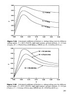
Figure
17-5.
Combustible
liquid
storage tank
in a
nonenclosed,
adequately
ventilated area.
(Reprinted
with
permission
from
API
RP
500.)
Figure
17-6.
Hydrocarbon
pressure
vessel
or
protected
fired
vessel
in a
nonenclosed,
adequately
ventilated
area.
(Reprinted
with
permission
from
API
RP
500.)
506
Design
of
GAS-HANDLING
Systems
and
Facilities
Figure
17-7.
Flammable
gas-operated
instruments
in an
adequately
ventilated
or
limited
ventilated
building
or
enclosure
with
all
devices
vented
to
the
outside.
{Reprinted
with
permission
from
API RP
500.)
Figure
17-8.
Flammable
gas-operated
instruments
in an
inadequately
ventilated
building
or
encbsure.
(Reprinted
with
permission from
API
RP
500.)
Electrical
Systems
507
Figure
17-9.
Process
equipment
vent
in a
nonencbsed,
adequately
ventilated
area
(top),
ami
instrument
or
control device vent
in a
nonenctosea,
adequately
ventilated
area
(bottom).
(Reprinted
with
permission
from
API
RP
500.)
508
Design
of
GAS-HANDLING
Systems
and
Facilities
Figure
17-10.
Relief
valve
in a
nonenclosed, adequately
ventilated
area.
(Reprinted
with
permission
from
AH
RP
500.)
Figure
17-11.
Ball
or
frig
launching
or
receiving
installation
in a
nonenclosed,
adequately
ventilated
area.
(Reprinted with
permission
from
API
RP
500.)
Electrical
Systems
509
Figure
17-12.
Compressor
or
pump
in an
adequately
ventilated,
nonendosed
area
(lop),
and
compressor
or
pump
in an
adequately
ventilated,
enclosed
area
(bottom).
(Reprinted
with
permission from
AM
KP
500.)
(text
continued
from
page 504)
determined. Specifically, most recommended practices
and
standards
consider ventilation
as
either
"adequate"
or
"inadequate."
API RP
500,
like
most recommended practices
for
area classification
in the
United
States, uses
the
basic principles
of the
definition
of
adequate ventilation
in
NFPA
No. 30,
"Flammable
and
Combustible Liquids
Code."
Adequate
ventilation
may be
defined
as
ventilation (natural
or
artificial) that
is
suf-
ficient
to
prevent
the
accumulation
of
significant quantities
of
vapor-air
mixtures
in
concentrations above
25% of
their lower
flammable
(explo-
sive)
limit
(LFL).
510
Design
of
GAS-HANDLING
Systems
and
Facilities
Figure
17-13.
Compressor
or
pump
in an
adequately
ventilated,
enclosed
area
(top),
and
compressor
or
pump
in an
inadequately
ventilated,
enclosed
area
(bottom).
(Reprinted
with
permission
from
API
KP
500.)
Although
the
above
definition
is
quite definitive,
it is
difficult
to
apply
to
actual facilities.
API RP 500
recommends several specific methods
of
achieving adequate ventilation.
All
methods require that there
be no
unventilated
areas where
flammable
vapors
or
gases might accumulate.
The
most common method
of
providing adequate ventilation
to
larger
buildings
is to
provide
at
least
1.0
cubic
foot
of air
volume
flow per
minute
per
square
foot
of floor
area,
but at
least
six (6) air
changes
per
hour,
by
either natural
or
mechanical ventilation. Some operators install
ventilation
equipment
to
obtain less than
six air
changes
per
hour under
normal circumstances
and
increase
ventilation
to six or
more
air
changes
per
hour
if gas
detectors sense
the
presence
of gas
above
20-25%
of the
lower
flammable
limit.