ARNOLD, K. (1999). Design of Gas-Handling Systems and Facilities (2nd ed.) Episode 2 Part 12 pps
Bạn đang xem bản rút gọn của tài liệu. Xem và tải ngay bản đầy đủ của tài liệu tại đây (1.31 MB, 25 trang )
Electrical Systems
511
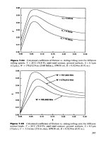
Figure
17-14.
Open
sump
in a
nonenclosed,
adequately
ventilated
area.
(Reprinted
with
permission
from
API RP
500.)
Figure
17-15.
Hazardous area location diagram
for a typical
offshore
production
platform.
512
Design
ofGAS-HANDLlNG
Systems
and
Facilities
For
buildings
of
1,000
ft
3
or
less (such
as a
typical meter house),
API
RP
500
defines
the
building
as
being adequately ventilated
if it has
sufficient
openings
to
provide twelve
air
changes
per
hour
due to
natural thermal
effects.
Assuming
the
building
has no
significant internal resistance
and
that
the
inlet
and
outlet openings
are the
same
size
and are
vertically sepa-
rated
and on
opposite walls,
the
required
free
area
of the
inlet
or
outlet
is;
where
A =
free
area
of
inlet
(or
outlet) openings (includes
a 50
percent effectiveness factor),
ft
2
Vol
=
volume
of
building
to be
ventilated,
ft
3
Tj
=
temperature
of
indoor air,
°R
T
2
=
temperature
of
outdoor
air,
°R
H' =
height
from
the
center
of the
lower opening
to
the
Neutral
Pressure Level (NPL),
ft
NPL
is the
point
on the
vertical surface
of a
building where
the
interior
and
exterior pressures
are
equal
It is
given
by:
where
H =
vertical (center-to-center) distance between
A]
and
A
2
,
ft
Aj
=
free
area
of
lower opening,
ft
2
A
2
=
free
area
of
upper opening,
ft
2
For
example, assume
a
building with inside
dimensions
of 8 ft
wide,
10
ft
long,
and 8 ft
high,
an
outside temperature
of
70°F,
inside temperature
of
80°F,
AI
=
A
2
and the
vertical (center-to-center) distance between
A
}
and
A
2
of 6 ft. The
height
from
the
center
of the
lower opening
to the
NPL
is:
*Equation
derived
from
1985
ASHRAE
Handbook
of
Fundamentals,
Chapter
22,
assum-
ing
an air
change every
five
(5)
minutes.
Refer
to the
ASHRAE Handbook, Chapter
22,
for
additional
information
on
naturally
ventilated
buildings.
Electrical
Systems
513
Therefore,
the
minimum area required
is:
A
=
(8X10X8)
1,200
[2.97(10/54Q)]
1/2
=
2.27
ft
2
for
both
the
inlet
and the
outlet
GAS
DETECTION
SYSTEMS
Combustible
gas
detection systems
are
frequently used
in
areas
of
poor
ventilation.
By the
early
detection
of
combustible
gas
releases
before
ignitible
concentration levels occur, corrective procedures such
as
shut-
ting
down equipment, deactivating
electrical
circuits
and
activating ven-
tilation
fans
can be
implemented prior
to
fire
or
explosion. Combustible
gas
detectors
are
also used
to
substantiate adequate ventilation. Most
combustible
gas
detection systems, although
responsive
to a
wide range
of
combustible gases
and
vapors,
are
normally calibrated specifically
to
indicate concentrations
of
methane since most natural
gas is
comprised
primarily
of
methane.
Gas
detectors
are
also used
to
sense
the
presence
of
toxic
gases—pri-
marily hydrogen sulfide
(H
2
S).
These
detectors
often activate warning
alarms
and
signals
at low
levels
to
ensure that personnel
are
aware
of
potential hazards before entering buildings
or are
alerted
to don
protec-
tive
breathing apparatus
if
they
are
already inside
the
buildings.
At
higher
levels, shut-downs
are
activated.
Consensus performance standards
and
guidance
for
installation
are
provided
for
combustible
gas
detectors
by ISA
SI2.13
and RP
12.13
and
for
hydrogen
sulfide
gas
detectors
by ISA
S12.15
and RP
12.15.
Required locations
of gas
detectors (sensors)
are
often
specified
by the
authority
having jurisdiction.
For
example,
API RP 14C
recommends
certain locations
for
combustible
detectors.
These
recommendations have
been legislated into requirements
in
U.S. Federal waters
by the
Minerals
Management Service.
RP 14C
should
be
referred
to for
specific details,
but,
basically, combustible
gas
detectors
are
required
offshore
in all
inad-
equately ventilated, classified, enclosed areas.
The
installation
of
sensors
in
nonenclosed
areas
is
seldom either required
or
necessary. Ignitible
or
high
toxic
levels
of gas
seldom accumulate
and
remain
for
significant
periods
of
time
in
such locations.
S14
Design
of
GAS-HANDLING
Systems
and
Facilities
When
specifying locations
for gas
detector
sensors,
consideration
should
be
given
to
whether
the
gases
being
detected
are
heavier
than
air
or
lighter than
air.
Hydrogen sulfide
is
heavier than
air and
therefore,
hydrogen
sulfide
detectors
are
normally installed near
the floor.
Since
sensors
may be
adversely
affected
(even rendered ineffective)
if
coated
with
water, they normally should
be
installed
18
to 36
inches above
the
floor
if
they
may be
subjected
to
flooding
or
washdown.
Most
combustible
gas
detector sensors
are
installed
in the
upper
por-
tions
of
buildings
for the
detection
of
natural
gas.
However,
in
many
cases
the
vapor which
flashes off oil in
storage tanks
can be
heavier than
air.
Below grade areas should
be
considered
for
sensor installations
where
heavier-than-air
vapors might collect.
Sensing heads should
be
located
in
draft-free
areas where
possible,
as
air flowing
past
the
sensors normally increases
drift
of
calibration, short-
ens
head
life,
and
decreases sensitivity.
Air
deflectors
are
available
from
sensor manufacturers
and
should
be
utilized
in any
areas
where
signifi-
cant
air flow is
anticipated (such
as air
conditioner plenum applications).
Additionally,
sensors should
be
located, whenever
possible,
in
locations
which
are
relatively
free
from
vibration
and
easily
accessed
for
calibra-
tion
and
maintenance. Obviously, this cannot always
be
accomplished.
It
usually
is
difficult,
for
example,
to
locate sensors
in the
tops
of
compres-
sor
buildings
at
locations which
are
accessible
and
which
do not
vibrate.
It
generally
is
recommended,
and
often
required, that
gas
detection
systems
be
installed
in a
fail-safe
manner. That
is, if
power
is
disconnect-
ed or
otherwise interrupted, alarm and/or process equipment shutdown
(or
other corrective action) should occur.
All
specific systems should
be
carefully
reviewed, however,
to
ensure that non-anticipated equipment
shutdowns
would
not
result
in a
more hazardous condition than
the
lack
of
shutdown
of the
equipment.
If a
more hazardous situation would occur
with shutdown, only
a
warning should
be
provided.
As an
example,
a
more hazardous situation might occur
if
blowout preventers were auto-
matically
actuated during
drilling
operations upon detection
of low
levels
of
gas
concentrations than
if
drilling personnel were only warned.
Concentration levels where alarm
and
corrective action should occur
vary.
If no
levels
are
specified
by the
authority having jurisdiction, most
recommend alarming (and/or actuating ventilation equipment)
if
com-
bustible
gas
concentrations
of 20
percent
LEL
(lower explosive
limit)
or
more
are
detected. Equipment shutdowns,
the
disconnecting
of
electrical
power,
production shut-in,
or
other corrective actions usually
are
recom-
mended
if 60
percent
LEL
concentrations
of
combustible
gas are
detect-
Electrical Systems
515
ed.
Hydrogen
sulfide
concentrations
of 5 ppm
usually require alarms
and
actuation
of
ventilation equipment
and
levels
of 15 ppm
usually
dictate
corrective action.
Special
attention should
be
given
to
grounding
the
sheathes
and
shields
of
cables interconnecting sensing heads
to
associated electronic
controllers.
To
avoid ground
loops,
care should
be
taken
to
ground
shields
only
at one
end, usually
at the
controller.
If
cables
are not
proper-
ly
grounded, they
may act as
receiving antennas
for
radio equipment
and
other
RF
generators
at the
location, transmitting
RF
energy
to the
elec-
tronic controller. This
RF
energy
can
cause
the
units
to
react
as if
com-
bustible
or
toxic
gas
were detected, causing
false
alarms
or
unwarranted
corrective action.
The use of
RF-shielded
enclosures
is
recommended
where
RF
problems
are
experienced
or
anticipated.
GROUNDING
A
ground,
as
defined
by the
National Electrical
Code,
is a
conducting
connection, whether intentional
or
accidental, between
an
electrical
cir-
cuit
or
equipment
and the
earth. Proper grounding
of
electrical
equip-
ment
and
systems
in
production facilities
is
important
for
safety
of
oper-
ating personnel
and
prevention
of
equipment damage.
The
term
"grounding" includes both electrical supply system grounding
and
equip-
ment
grounding.
The
basic reasons
for
grounding
an
electrical supply system
are to
limit
the
electrical
potential difference (voltage) between
all
uninsulated
conductive equipment
in the
area;
to
provide isolation
of
faults
in the
system;
and to
limit overvoltage
on the
system under various conditions.
In
the
case
of a
grounded system
it is
essential
to
ground
at
each sepa-
rately
derived voltage level.
Electrical
Supply
System
Grounding
The
electrical supply system neutral
can be
grounded
or
ungrounded,
but
there
is an
increasing trend
in the
industry toward grounded systems.
Ungrounded power systems
are
vulnerable
to
insulation failures
and
increased shock hazards
from
transient
and
steady state overvoltage con-
ditions. Grounding
of an
electrical
supply system
is
accomplished
by
connecting
one
point
of the
system (usually
the
neutral)
to a
grounding
electrode.
The
system
can be
solidly grounded,
or the
ground
can be
516
Design
of
GAS-HANDLING
Systems
and
Facilities
through
a
high
or low
resistance.
A
resistance
ground
is
more suited
for
certain
systems—particularly
when process continuity
is
important.
Equipment
Grounding
Equipment grounding
is the
grounding
of
non-current carrying con-
ductive
parts
of
electrical equipment
or
enclosures containing
electrical
components.
This
provides
a
means
of
carrying currents
caused
by
insu-
lation
failure
or
loose connections
safely
to
ground
to
minimize
the
dan-
ger of
shock
to
personnel.
The
following equipment (not
all
inclusive) requires adequate
equip-
ment
grounding:
1.
Housings
for
motors
and
generators
2.
Enclosures
for
switchgear
and
motor
control
centers
3.
Enclosures
for
switches, breakers, transformers, etc.
4.
Metal
frames
of
buildings
5.
Cable
and
conduit systems
6.
Conductive cable tray systems
7.
Metal storage tanks
Groundling
for
Static
Electricity
A
discharge
to
ground
of
static electricity accumulated
on an
object
can
cause
a
fire
or
explosion.
A
static charge
can
have
a
potential
of
10,000
volts,
but
because
it has a
very small current potential,
it can be
safely
dissipated
through
proper
bonding
and
grounding.
Bonding
two
objects
together (connecting them electrically) keeps them
at the
same
potential (voltage), minimizing spark discharge between them. Generally,
equipment
bonded
to
nearby conducting objects
is
adequate
for
static
grounding.
The
equipment grounding conductor carries static charges
to
ground
as
they
are
produced.
Grounding
for
Lightning
Elevated structures such
as
vent stacks, buildings, tanks,
and
overhead
lines must
be
protected against direct lightning strikes
and
induced light-
ning voltages. Lightning
arrestors
or
rods
are
installed
on
such objects
and
connected
to
ground
to
safely dissipate
the
lightning charges.
Electrical Systems
517
Grounding
Methods
Onshore, grounding
is
generally provided
by
installing
a
ground loop,
made
of
bare copper conductors, below
the finished
grade
of the
facility.
Individual
equipment grounding conductors
and
system grounding
conductors
are
then connected
to
this ground loop, usually
by a
thermow-
eld
process.
A
number
of
grounding
electrodes,
generally
%-in.
to
%-in.
diameter
and
8-10
ft
long
copper
or
copper-clad steel
rods,
are
driven
into
the
earth
and
connected
to the
ground loop.
The
number
of
ground
rods required
and the
depth
to
which they should
be
driven
are
calculated
based
on the
resistivity
of the
soil
and the
minimum
required resistance
of
the
grounding system.
Most
grounding systems
are
designed
for
less than
5
ohms resistance
to
ground.
A
continuous underground metallic water piping system
can
provide
a
satisfactory grounding electrode.
The
National Electrical Code,
Article
250, covers requirements
for
sizing ground loops
and
equipment/
system
grounding conductors.
Offshore,
the
equipment
and
system ground
conductors
are
connected
to
the
facility's metal
deck,
usually
by
welding.
The
metal deck serves
the
function
of the
ground loop
and is
connected
to
ground
by
virtue
of
solid
metal-to-metal
contact with
the
platform jacket.
D.C
POWER
SUPPLY
Generally, electrical control systems
are
designed
"Fail-Safe."
If
power
is
temporarily lost, unnecessary shutdown
of the
process
may
occur. Thus,
most
safety
systems such
as
fire
and gas
detectors,
Nav-Aids,
communi-
cations,
and
emergency lighting require standby D.C. power.
Most
D.C. power systems include rechargeable
batteries
and a
battery
charger system which automatically keeps
the
batteries
charged when
A.C. power
is
available.
In
some systems,
a
D.C to-A.C. inverter
is
pro-
vided
to
power some A.C. emergency equipment such
as
lighting. Solar
cells
can
also
be
used
for
charging batteries. Solar cells
are
frequently
used
at
unmanned installations without on-site power generation. Some-
times
non-rechargeable batteries
are
also used
at
such
locations.
518
Design
of
GAS-HANDLING
Systems
and
Facilities
Batteries
Numerous
types
of
batteries
are
available.
A
comparison
of
batteries
by
cell type
is
shown
in
Table
17-1.
Rechargeable batteries emit hydro-
gen
to the
atmosphere,
and
hence
must
be
installed
such that hydrogen
does
not
accumulate
to
create
an
explosion hazard. Ventilation should
be
provided
for
battery compartments.
Batteries should normally
be
installed
in an
unclassified area. Howev-
er,
if
installed
in
Division
2
areas,
a
suitable disconnect switch must
be
installed
to
disconnect
the
load prior
to
removing
the
battery
leads
and
thus
avoid
a
spark
if the
battery leads
are
disconnected under load condi-
tions.
Batteries should
not be
installed
in
Division
1
areas.
Battery
Chargers
Battery
chargers
are
selected
based
on
cell
type
and
design
ambient
conditions. Chargers connected
to
self-generated power should
be
capa-
ble of
tolerating
a 5%
frequency variation
and a 10%
voltage variation.
Standard
accessories
of
chargers include equalizing timers, A.C.
and
D.C.
fuses
or
circuit breakers, current-limiting features,
and
A.C.
and
D.C.
ammeters
and
voltmeters. Optional accessories such
as low
D.C.
voltage
alarms, ground
fault
indications,
and
A.C. power
failure
alarms
are
usually
available.
Chargers
are
normally installed
in
unclassified areas. However,
it is
possible
to
purchase
a
charger suitable
for
installation
in a
classified
area.
CATEGORIES
OF
DEVICES
Electrical switches, relays,
and
other devices
are
described
for
safety
reasons
by
several general
categories.
Since these
devices
are
potential
sources
of
ignition during normal operation (for example, arcing con-
tacts)
or due to
malfunction,
the
area classification limits
the
types
of
devices
which
can be
used.
High-Temperature
Devices
High-temperature devices
are
defined
as
those devices that operate
at a
temperature
exceeding
80
percent
of the
ignition temperature (expressed
in
Celsius)
of the gas or
vapor involved.
The
ignition temperature
of
nat-
ural
gas
usually
is
considered
to be
900°F
(482°C). Therefore,
a
device
is
Table
17-1
Comparison
of
Batteries
by
Cell
Type
Projected
Projected
Wet
Shelf
Useful
life
Cycb
Life
1
Life**
Type
(Years)
(Number
of
Cycles)
(Months)
Primary
1-3 1 12
SLI
(Starting,
%-2
400-500
2-3
Lighting
&
Ignition)
(Automotive
Type)
Lead
Antimony
8-15
600-800
4
Lead
Calcium
8-15
40-60
6
Comments***
Least maintenance.
Periodic
replacement.
Cannot
be
recharged.
High
hydrogen emission.
High
maintenance.
Not
recommended
for float
service
or
deep discharge.
Low
shock tolerance.
Susceptible
to
damage
from
high temperature.
High
hydrogen emission.
Periodic equalizing
is
required
for float
service
and
full
recharging.
Low
shock tolerance.
Susceptible
to
damage
from
high
temperature.
Low
hydrogen emission
if floated at
2.17
volts
per
cell.
Periodic equalizing charge
is not
required
for float
service
if
floated at
2.25
volts
per
cell.
However, equalizing
is
required
for
recharging
to
full
capacity.
When
floated
below
2.25
volts
per
cell,
equalizing
is
required.
Susceptible
to
damage
from
deep discharge
and
high
temperature.
Low
shock tolerance.
(table
continued
on
next
page)
Table
17-1
(Continued)
Comparison
of
Batteries
by
Cell
Type
Projected
Projected
Wet
Shelf
Useful
Life
Cycle
Life*
Life**
Type
(Years)
{Number
erf
Cycles)
(Months)
Comments***
Lead
Selenium
20+
600-800
6 Low
hydrogen emission
if
floated
at
2.17
volts
per
cell.
Periodic equalizing charge
is not
required
for float
service
if
floated at
2.25 volts
per
cell. However, equalizing
is
required
for
recharging
to
full
capacity. When
floated
below 2.25 volts
per
cell, equalizing
is
required.
Low
shock
tolerance.
Susceptible
to
damage
from
high
temperature.
LeadPlante
20+
600-700
4
Moderate hydrogen emission.
(Pure
Lead) Periodic equalizing
charge
is
required
for float
service
and
full
recharging.
Low
shock tolerance.
Susceptible
to
damage
from
high
temperature.
Nickel
Cadmium
25+
1000+ 120+
Low
hydrogen emission.
(Ni-Cad)
Periodic equalizing charge
is not
required
for float
service,
but is
required
for
recharging
to
full
capacity.
High
shock tolerance.
Can
be
deep cycled.
Least susceptible
to
temperature.
Can
remain discharged without damage.
C»wtt">\
of
\P1
RP 14F
*f
\
(
le
life
n
the
number,
/,
u/<n
atnhit.fi
nnu
«
•
si
hatred
ba'w-
^
"*'
't-raif
r»-l<.
%>'f
'rfi"
oriqiml
ampere-hour
capacity.
A
cycle
is
defined
as the
removal
of
15%
oj
the
lated
batten
ampei
e
hour
capacity
"~l\(t
\htflttije
ii
defined
ds
the
time
that
m
initial*
nlh
i
hatst
i
hatit'n
tan he
>/.>»«*
at
7
~"f
until
permanent
cell
damage
wcurs.
'
"*Float
ivltage^
listed
aie
tor
77
f
Electrical
Systems
521
considered
a
high-temperature
device
in a
natural
gas
environment
if the
temperature
of the
device exceeds 726°F
(385°C).
The
ignition
tempera-
ture
of
hydrogen
sulfide
is
usually considered
to be
518°F
(270°C),
In
classified
areas, high-temperature devices must
be
installed
in
explosion-
proof enclosures unless
the
devices
are
approved
for the
specific area
by
a
nationally
recognized testing laboratory (NRTL).
Weather-Tight
Enclosures
Electrical equipment
can be
mounted
in
various types
of
enclosures.
A
weather-tight
enclosure normally
has a
gasket
and
does
not
allow
air
(and
the
moisture contained
in the
air)
to
enter
the
enclosure. Offshore,
such
an
enclosure,
if
properly
closed,
will help protect
the
enclosed
electrical
equipment
from
corrosion
due to
salt water spray. These
types
of
enclo-
sures
can be
used
in
Division
2
areas provided they
do not
enclose arc-
ing,
sparking
or
high temperature devices.
Explosion-Proof
Equipment
described
as
"explosion-proof"
is
equipment
installed
in
enclosures that will withstand internal explosions
and
also prevent
the
propagation
of
flame
to the
external atmosphere.
As the
gases generated
by
the
explosion expand, they must
be
cooled before reaching
the
sur-
rounding
atmosphere.
Equipment
may be
rated explosion-proof
for
certain gases
but not
oth-
ers.
For
example,
an
enclosure
may be
rated
as
suitable
for
Group
D
gases,
but not for
Group
B
gases. Therefore,
it is not
satisfactory
to
mere-
ly
state that equipment must
be
"explosion-proof";
one
must specify
"Explosion-proof
for
Class
I,
Group
D," as an
example. Because explo-
sion-proof
enclosures must have
a
path
to
vent
the
expanding gases cre-
ated
by the
explosion, explosion-proof enclosures
"breathe"
when
the
temperature
inside
the
enclosure
is
different
from
that outside. That
is,
they
cannot
be
weather tight.
As a
result, moisture frequently
is
intro-
duced
into explosion-proof enclosures. Unless suitable drains
are
provid-
ed
in low
spots, water
can
accumulate inside
the
enclosure
and
damage
enclosed electrical equipment.
The
surface temperature
of
explosion-proof enclosures cannot
exceed
that
of
high-temperature devices. Equipment
can be
tested
by
nationally
recognized testing laboratories
and
given
one of 14
"T"
ratings,
as
indi-
cated
in
Table 17-2. This equipment
may
exceed
the "80
percent rule,"
522
Design
of
GAS-HANDLING
Systems
and
Facilities
but
the
"T"
rating must
be
below
the
ignition
temperature
of the
specific
gas
or
vapor involved.
As an
example, equipment rated
Tl has
been veri-
fied
not to
exceed 842°F and, therefore,
is
suitable
for
most natural
gas
applications.
Hermetically
Sealed
Devices
Hermetically
sealed devices
are
devices sealed
to
prevent flammable
gases
from
reaching enclosed sources
of
ignition. These devices
are
suit-
able
for use in
Division
2 and
unclassified areas.
Hermetically
sealed electrical devices must
be
verified
by a
testing
laboratory
to
meet mechanical abuse
and to
withstand aging
and
expo-
sure
to
expected chemicals. Devices
"potted"
with common silicones
and
similar
materials
by an end
user
or
even
a
manufacturer, without
testing,
and
devices merely provided with
O-rings
seldom meet acceptable
crite-
ria.
Normally, hermetically
sealed
devices
must
be
sealed
through metal-
to-metal
or
glass-to-metal
fusion.
Many electrical relays, switches,
and
sensors
are
available
as
hermetically sealed devices
for
common
oil and
gas
producing facility applications. Hermetically sealed devices
are
often
desirable
to
protect electrical contacts
from
exposure
to
salt
air and
other
contaminants.
Table
17-2
Temperature
Ratings
of
Explosion-Proof
Enclosures
Maximum
Temperature
Identification
°C
°F
Number
450 842 Tl
300
572 T2
280
536 T2A
260
500 T2B
230
446 T2C
215
419 T2D
200 392 T3
180
356
T3A
165
329 T3B
160
320
T3C
135
275 T4
120
248
T4A
100
212 T5
J*5
J85
T6
Electrical Systems
523
Purged
Enclosures
Purged
enclosures
are
those enclosures provided
with
a
purge (static
or
dynamic)
of air or
other inert
gas to
prevent enclosed
electrical
equip-
ment
from
coming
in
contact with surrounding atmospheres which might
be
flammable.
NFPA Publication
No. 496
provides
detailed
requirements
for
the
design
of
purged enclosures. Requirements
are
different
for
dif-
ferent
size enclosures. Enclosures
can be as
small
as a box for a
single
electrical
switch
or as
large
as a
control room. Requirements
vary
for
three
recognized types
of
purging: Type
X, the
reduction
from
Division
1
to
unclassified;
Type
Y, the
reduction
from
Division
1 to
Division
2; and
Type
Z, the
reduction
from
Division
2 to
unclassified.
If
purging
is
uti-
lized
in
areas
of
high humidity
or in
areas where
the
atmosphere
may
contain
flammable gases
or
contaminants, clean dehydrated
air or an
inert
gas
should
be
used
as a
purge
to
prevent explosions
or
damage
to
enclosed electrical equipment. Properly designed purged enclosures
can
eliminate
the
need
for
explosion-proof enclosures.
Nonincendive
Devices
A
nonincendive device
is one
which will
not
release
sufficient
energy
under normal operating conditions
to
ignite
a
specific substance. Under
abnormal conditions, such
as a
malfunction
of the
device,
it may
release
enough
energy
to
cause ignition. Because
of
this, such devices
are
suit-
able
for
use
only
in
Division
2 and
unclassified areas.
Intrinsically
Safe
Systems
Intrinsically
safe
systems
are
electrical systems which
are
incapable
of
releasing
sufficient
electrical
or
thermal energy under normal
or
abnor-
mal
equipment operating conditions
to
cause ignition
of a
specific
flam-
mable mixture
in its
most easily ignitible state.
For
example, intrinsically
safe
equipment suitable
for a
Class
I,
Group
D
application cannot ignite
a
mixture
of
methane
and air in its
most easily ignitible state (approximate-
ly
10
percent methane
by
volume), even,
for
example,
if
adjacent
wiring
terminals
are
accidentally shorted with
a
screwdriver.
The
design
of
intrinsically
safe
equipment
is
governed
by the
rules
of
NFPA
Publication
No.
493,
"Standard
for
Intrinsically Safe Apparatus
and
Associated Apparatus
for Use in
Class
I, II, and
III,
Division
1,
Haz-
ardous
Locations."
It is
cautioned, however, that
the
design
of
intrinsical-
524
Design
of
GAS-HANDLING
Systems
and
Facilities
ly
safe equipment
is a
highly specialized skill
and
normally best
left
to
those
specifically trained
in
that
art.
The
installation
of
equipment which
has
been
rated
by a
testing organization
as
intrinsically safe should
fol-
low
the
guidelines
of ISA RP
12.6,
"Recommended Practice
for
Installa-
tion
of
Intrinsically Safe Systems
for
Hazardous (Classified) Locations."
It
must
be
realized that there
is no
such thing
as an
intrinsically
safe
tem-
perature
transmitter, pressure switch,
or
other such sensor; these devices
must
be
properly
installed
in
intrinsically
safe
systems
to
ensure
safety
from
ignition
of
flammable
gas or
vapor.
The
mere
fact
that voltage, current,
or
even both,
are at low
levels does
not
guarantee
a
circuit
to be
intrinsically safe, even though intrinsically
safe
circuits
do
utilize
relatively
low
voltage
and
current levels. Intrinsi-
cally
safe systems employ electrical barriers
to
assure that
the
system
remains intrinsically safe.
The
barriers
limit
the
voltage
and
current
com-
binations
so as not to
present
an
ignition hazard should
a
malfunction
develop.
Typically, devices "upstream"
of
barriers
are not
intrinsically
safe
and are
installed
in
control rooms
or
other unclassified locations.
All
devices
and
wiring
on the
"downstream" side
of the
barriers
are
intrinsi-
cally
safe
and can be
installed
in
classified areas.
An
additional benefit
of
intrinsically safe systems
is the
reduction
of
electrical shock hazards.
It is
cautioned,
however, that intrinsically safe
systems
are not
necessarily tested specifically
for
personnel shock hazards.
Circuit
capacitance
and
inductance, including
the
values
of
these
para-
meters
for
interconnecting wiring,
are
integral parts
of the
overall
analy-
sis.
It is not
always possible
to
assure that
the
system will
be
maintained
as
designed with only approved intrinsically safe components
and
with
circuits
of the
capacitance
and
inductance
as
originally installed.
For
this
reason, intrinsically safe systems
are
used primarily
at
locations where
there
are
sufficiently trained personnel
to
assure that
the
intrinsic
safety
of
the
system
is
always maintained.
LIMITATIONS
ON
INSTALLATION
OF
ELECTRICAL
DEVICES
IN
HAZARDOUS
AREAS
Transformers
In
Division
1
areas,
transformers must
be
installed
in
approved vaults
if
they contain
a
flammable liquid.
If
they
do not
contain
a
flammable
liquid,
they must either
be
installed
in
vaults
or be
approved explosion-
proof.
In
Division
2
areas, "standard" transformers
are
acceptable,
but
Electrical
Systems
525
they
must
not
contain circuit breakers
or
other arcing devices. Thus,
common self-contained transformer/distribution
panel
packages
which
contain
circuit breakers
are not
suitable
for
Division
2
areas. Standard
practice
is to
provide separate
units—installing
the
breakers
in
explo-
sion-proof
enclosures
or in
unclassified areas.
Meters/
Instruments/
and
Relays
In
Division
1
areas, meters, instruments, relays,
and
similar equipment
containing
high-temperature
or
arcing devices must
be
installed
in
approved explosion-proof
or
purged enclosures. Unless such devices
are
specifically labeled
as
suitable
for
Class
I,
Division
1
areas,
it is
best
to
assume they
are not
suitable.
Arcing
contacts
in
Division
2
areas must
be
installed
in
explosion-
proof enclosures,
be
immersed
in
oil,
be
hermetically
sealed,
or be
non-
incendive.
High-temperature devices must
be
installed
in
explosion-proof
enclosures.
Fuses must
be
enclosed
in
explosion-proof enclosures unless
the
fuses
are
preceded
by an
explosion-proof, hermetically sealed,
or
oil-
immersed
switch
and the
fuses
are
used
for
overcurrent
protection
of
instrument
circuits
not
subject
to
overloading
in
normal use.
Figure
17-16
depicts typical devices containing arcing contacts
enclosed
in
explosion-proof enclosures. Figure
17-17
shows typical
explosion-proof alarm devices.
A
telephone instrument suitable
for
Class
I,
Divisions
1 and 2,
Group
D
classified areas
is
shown
by
Figure 17-18.
Motors
and
Generators
In
Division
1
areas, motors
and
generators must
be
either explosion-
proof
or
approved
for the
classification
by
meeting specific requirements
for
a
special ventilation system, inert gas-filled construction,
or a
special
submerged
unit.
Although explosion-proof motors
are
expensive, they
normally
are
available. Explosion-proof generators normally
are not
available.
Standard
Open
or
Totally-Enclosed Fan-Cooled (TEFC) generators
and
motors
are
acceptable
in
Division
2
areas
if
they
do not
contain
brushes
or
other arcing contacts
or
high-temperature
devices. Three-
phase TEFC motors
are
acceptable
in
Division
2
locations,
but
single-
phase
motors usually contain arcing devices
and are not
acceptable
(text
continued
on
page 529)
17-16.
Typical
devices
containing arcing
contacts
in
explosion-proof
enclosures,
{Courtesy
of
Crouse-Hinds
Electrical
Construction
Materials,
a
division
of
Cooper
Industries,
Inc.]
528
Design
of
GAS-HANDLING
Systems
and
Facilities
Figure
17-17.
Standard explosion-proof
alarm
devices.
(Courtesy
of
Crouse-Hinds
Electrical
Construction
Materials,
a
division
of
Cooper Industries, Inc.)
Figure
17-18.
Typical telephone instrument suitable
for
Class
I,
Divisions
1 and 2,
Group
D
areas.
(Courtesy
of
Crouse-Hinds
Electrical Construction
Materials,
a
division
of
Cooper
Industries,
Inc.]
Electrical
Systems
529
(text
continued
from
page
525)
unless
the
arcing
devices
are
installed
in
explosion-proof
enclosures.
D.C. motors contain brushes
and are not
acceptable
for
classified areas
unless
they
are
provided
with
approved purged enclosures.
If
motor
space heaters
are
provided, their surface temperature must
not
exceed
80
percent
of the
ignition temperature, expressed
in
degrees Celsius,
of the
potential
gas or
vapor which could
be
present.
Lighting
Fixtures
Lighting
fixtures installed
in
Division
1
areas must
be
explosion-proof
and
marked
to
indicate
the
maximum wattage
of
allowable lamps. Also,
they
must
be
protected against physical damage
by a
suitable guard
or by
location.
In
both Division
1 and
Division
2
areas pendant fixtures must
be
sus-
pended
by
conduit stems
and
provided with
set
screws
to
prevent loosen-
ing.
Stems over
12
inches
in
length
must
be
laterally braced
within
12
inches
of
fixtures.
All
portable lamps
in
Division
1
areas must
be
explosion-proof. Figures
17-19,
17-20,
and
17-21 show typical explosion-proof lighting fixtures.
Lighting
fixtures
for
Division
2
locations
must
be
either explosion-
proof
or
labeled
as
suitable
for
Division
2 for the
particular Class
and
Group
involved.
Figure 17-22 shows typical Division
2
lighting
fixtures.
WIRING
METHODS
Documents specified
by
local authorities having
jurisdiction
provide
very
explicit rules
for the
specific types
of
electrical equipment that
are
permitted
in the
various hazardous (classified)
areas
and the
methods
by
which
the
equipment must
be
installed.
Since
it is
rare
to
encounter Class
II
and
Class
III
hazardous (classified) areas
in oil and gas
producing
operations,
only
Class
I
requirements
will
be
addressed
further.
In the
United
States,
the
National
Electrical
Code
is
referenced
by
most enforc-
ing
agencies.
For
fixed platforms
in the
Outer Continental Shelf (OCS),
API RP 14F is
referenced
as the
primary design
and
installation docu-
ment
by the
Minerals Management Service (MMS),
the
enforcing
agency.
RP 14F
deviates somewhat
from
the
National
Electrical
Code
in
wiring
methods required, relying
heavily
on
U.S. Coast Guard
philoso-
530
Design
of
GAS-HANDLING
Systems
and
Facilities
Figure
17-19.
Typical
Class
I,
Division
1
lighting
fixures.
(Courtesy
of
Grouse-Minds
Electrical
Construction
Materials,
a
division
of
Cooper
Industries,
Inc.]
Figure
17-20.
Typical
explosion-proof
fluorescent
lighting
fixtures.
(Courtesy
of
Crouse-Hinds
Electrical
Construction
Materials,
a
division
of
Cooper Industries,
Inc.]
Electrical
Systems
531
figure
17-21.
Standard explosion-proof portable lamp suitable
for
Class
I,
Divisions
1 and 2,
Group
D
areas,
(Courtesy
of
Crouse-Hinds
Electrical
Construction
Materials,
a
division
of
Cooper
Industries,
Inc.]
phy.
Except
for
these specific wiring deviations, however,
RP 14F
refer-
ences
the
National Electrical Code.
Division
1
Areas
In
Division
1
areas,
the
National Electrical Code
(NEC)
allows
only
the
following
wiring methods:
1.
Threaded rigid metal conduit
2.
IMC
(Intermediate Metal Conduit)
3.
MI
cable (Mineral Insulted Cable)
4.
Explosion-proof
(XP) flexible connections
Threaded rigid metal conduit must
be
threaded with
an NPT
standard
conduit
cutting
die
that provides
%-in.
taper
per
foot, must
be
made
up
532
Design
of
GAS-HANDLING
Systems
and
Facilities
Figure
!
7-22.
Standard
lighting
fixtures
suitable
for
Class
I,
Division
2,
Group
D
areas.
(Courtesy
of
Crouse-Hinds
Electrical
Construction
Materials,
a
division
of
Cooper
Industries,
Inc.)
wrench tight
or
provided with bonding jumpers
at
joints,
and
must have
at
least
five
full
threads engaged. These precautions
are
necessary
to
min-
imize
sparking across threads when
a
fault
current
flows
through
the
con-
duit
system
and to
provide proper distance
for
escaping gases
to
cool
if
an
explosion occurs
in the
conduit. Pipe designed
for
fluids,
and not
approved
as
electrical equipment, must
not be
used—regardless
of
wall
thickness.
For
offshore
locations where ignitible gas-air concentrations
are
nei-
ther
continuously
present
nor
present
for
long
periods,
API RP 14F
also
allows type
MC
cable with
a
continuous aluminum sheath
and an
outer
impervious
jacket (such
as
PVC)
and
armored cables
satisfying
ANSI/
Institute
of
Electrical
and
Electronic Engineers (IEEE) Standard
No.
45.
API
RP 14F
does
not
recommend
IMC for
offshore installations
and
cau-
tions
users that installations
of MI
cable require special precautions.
The
insulation
of MI
cable
is
hygroscopic (able
to
absorb moisture
from
the
atmosphere).
The use of
certain non-armored cables
is
acceptable
to API RP 14F in
Division
1
areas
on
drilling
and
workover
rigs
where ignitible concentra-
tions
of
gases
and
vapors
do not
occur
for
appreciable lengths
of
time.
Electrical
Systems
533
However,
the
non-armored cables must
satisfy
IEEE
383 or
IEEE
45
flarn-
mability
requirements
and
other requirements specified
in API RP
14F.
NEC
allows
the use of
portable cord connecting
portable
lighting
equipment
and
other portable utilization equipment
with
the
fixed
por-
tion
of its
supply circuit
in
Class
I,
Division
1 and 2
areas, provided:
1.
The
cord
is
rated
for
extra-hard
service
(frequently referred
to as
"Heavy-Duty
SO
Cord"),
and
2.
An
approved grounding connector
is
provided inside
the
cord's
outer
jacket,
For all
other applications (temporary
or
permanent)
in
Division
1
areas,
portable cord (whether rated
for
extra-hard service
or
not)
is
specifically
disallowed.
Division
2
Areas
In
Division
2
areas,
the NEC
allows
the
wiring methods that follow:
1.
Threaded rigid metal conduit,
2.
IMC,
3.
Enclosed gasketed busway,
4.
Enclosed gasketed wireway,
5.
PLTC cable (Power Limited Tray
Cable),
6. MI, MC, MV, TC, or SNM
cable
with
approved
termination fit-
tings,
and
7.
Flexible cord approved
for
extra-hard service, flexible metal con-
duit,
and
liquidtight flexible conduit
for
limited flexibility.
A
suit-
able grounding conductor must
be
provided inside
the
flexible
cord's outer
jacket.
Flexible conduit must
be
bonded with
an
exter-
nal
jumper
or an
approved
internal system jumper; external bonding
jumpers
are
disallowed
for flexible
conduit exceeding
six
feet. Typi-
cal
liquidtight
and flexible
cord connectors
and an
explosion-proof
flexible
connection
are
shown
in
Figure
17-23.
Wiring
System
Selection
The
designer must decide
at
inception whether
to
provide
a
cable sys-
tem
or a
conduit system. Although
both
systems have specific advan-
tages,
the
present trend
is
toward
the
installation
of
cable systems rather
than
conduit systems. Offshore,
the
vast majority
of new
systems
are
534
Design
of
GAS-HANDLING
Systems
and
Facilities
Figure
17-23.
Liquidtight
and
flexible
cord connectors.
(Courtesy
of
Crouse-Hinds
Electrical
Construction
Materials,
a
division
of
Cooper
Industries,
Inc.]
cable—particularly
a
cable
with
a
gas/vapor-tight continuous corrugated
aluminum
sheath,
rated
Type
MC, and
with
an
overall
jacket
(usually
PVC)—and
normally installed
in
cable
tray.
This cable/cable tray system
is
usually less expensive
to
install than
a
conduit system (even though
the
materials
may be
more expensive)
and
offers
the
advantage
of not
requir-
ing
sealing
fittings
at
area classification boundaries. Additionally,
the
cable
tray system normally lends itself
to
easier
and
less
expensive
expansions than
the
conduit system.
Cable
trays
are
generally made
of
fiberglass,
aluminum, stainless steel,
or
galvanized steel materials.
Conduit systems have
the
advantage
of
offering
greater
mechanical
protection
to
enclosed conductors,
but
they
can
easily lose this advantage
through
corrosion
if not
properly maintained.
A
conduit system which
corrodes
on the
inside
can
provide
false
security; although
the
outside
appears completely sound,
the
system
may not
contain
an
internal explo-
sion.
Extremely rapid corrosion
will
occur
in
salt-air environments
for
most
conduit systems
of
ferrous materials.
In
offshore
environments.
Electrical
Systems
535
conduit
of
copper-free aluminum (normally defined
as
0.4%
or
less cop-
per)
is
normally preferred.
If
aluminum conduit
is
supported
by
ferrous
supports,
the
aluminum must
be
carefully isolated
from
the
ferrous mate-
rial, or
rapid corrosion will occur
due to
galvanic action. Ferrous con-
duits,
normally satisfactory
in
heated areas (such
as
buildings containing
operating
engines) and,
of
course,
in
areas
not
subjected
to
corrosive ele-
ments,
offer
the
advantage
of
magnetic
sheilding—-particularly
desirable
for
communications
and
instrumentation circuits.
Conduits coated with
PVC and
other materials, preferably coated
on
the
inside
as
well
as on the
outside, should
be
considered
for
corrosive
environments.
It
should
be
noted, however, that coated conduit
is
signifi-
cantly
more expensive than non-coated conduit,
and
serves
no
real over-
all
deterrent
to
corrosion
unless coated fittings
are
also
provided
and
extreme care
is
taken during installation
to
avoid damaging
the
coating.
The
threaded ends
of the
conduit, which cannot
be
coated without elimi-
nating electrical continuity,
are
probably
the
weakest link
of
most coated
conduit
systems, even though some manufacturers provide couplings
designed
to
prevent moisture intrusion.
Junction
Boxes
and
Conduit
Fittings
A
box or
fitting must
be
installed
at
each conductor
splice
connection
point,
receptacle, switch, junction point,
or
pull point
for the
connection
of
conduit system.
In
Division
1
areas only explosion-proof
boxes
or
fit-
tings
are
allowed. General purpose
gasketed
cover type fittings
are
allowed
in
Division
2
areas.
Boxes
and
fittings made
of
copper-free aluminum
are
generally used
in
offshore
application
as
they provide better corrosion resistance. Galva-
nized
steel
or
metal
fittings
with
a PVC
coating
are
also
used
in
offshore
applications.
It
should
be
noted that, although PVC-coated fittings pro-
vide
resistance
to
exterior corrosion, they
do not
stop interior corrosion.
Also,
the
cost
of
PVC-coated fittings
is
appreciably higher,
and
they
require
careful
handling
and
installation
to
assure that
the PVC
coating
is
not
damaged. Typical explosion-proof junction boxes
and
conduit
fittings
are
shown
in
Figure 17-24.
Sealing
Fittings
Conduit
and
cable sealing fittings
as
shown
in
Figures 17-25
and
17-
26 are
provided
for the
following purposes: