ARNOLD, K. (1999). Design of Gas-Handling Systems and Facilities (2nd ed.) Episode 2 Part 13 docx
Bạn đang xem bản rút gọn của tài liệu. Xem và tải ngay bản đầy đủ của tài liệu tại đây (1.35 MB, 25 trang )
536
Design
of
GAS-HANDLING
Systems
and
Facilities
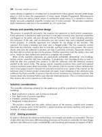
Figure
17*24.
Standard
explosion-proof
junction
boxes
and
conduit
fittings.
(Courtesy
of
Crouse-H/nc/s
Electrical
Construction
Materials,
a
division
of
Cooper
Industries,
Inc.)
1.
Confine internal
explosions
to
explosion-proof
enclosures
and
con-
duit
systems.
2.
Minimize
the
passage
of
gases,
and
prevent
the
passage
of flame,
through conduit
or
cable.
3.
Prevent process
gas or
liquid
in
process piping from entering
con-
duit
or
cable systems.
4.
Prevent "pressure piling."
Pressure piling
is a
phenomenon caused
by the
fact that ignition
in an
enclosure
can first
pre-compress gases
in a
conduit
or
other
enclosure
to
Electrical
Systems
537
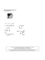
Figure
17-25. Standard
sealing
fittings.
(Courtesy
of
Crouse-Hinds
Electrical
Construction
Materials,
a
division
of
Cooper
Industries,
Inc.]
Figure
17-26.
Cutaway
drawing
of a
property
installed
sealing
fitting.
(Courtesy
of
Crouse-Hinds
Electrical
Construction
Materials,
a
division
of
Cooper
Industries,
Inc.]
S38
Design
of
GAS-HANDLING
Systems
and
Facilities
which
It is
connected. When
pre-compressed
gases
are
then
ignited
in the
second enclosure, pressures exceeding those
for
which
it has
been
tested
can
be
reached.
Receptacles
and
Attachment
Plugs
Receptacles
and
attachment plugs
for
Class
I,
Division
1 and 2
areas
must
be
approved
for the
area. They must provide
a
means
of
connection
to the
grounding conductor
of a
flexible cord. Typical Class
I
receptacles
and
attachment plugs
are
shown
by
Figure
17-27.
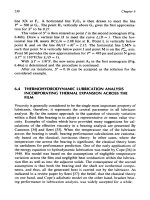
Figure
17-27.
Typical Class
I,
Division
1 and 2
receptacles
and
attachment plugs.
(Fop,
courtesy
of
Crouse-Hinds
Electrkal
Construction
Atoteria/s,
a
division
of
Cooper
Industries,
Inc.;
bottom,
courtesy
ofAppleton
Electric
Co.,
a
division
of
Emerson
Electric
Co.)
Electrical Systems
539
Seal
Locations
Seals
must
be
installed
in the
following locations:
1.
Seals
are
required
at
entries
by
conduit
or
cable
to
explosion-proof
enclosures
containing arcing
or
high-temperature devices
in
Divi-
sion
1 and
Division
2
locations.
It is not
required
to
seal
\
1
A
in. or
smaller conduits into explosion-proof enclosures
in
Division
1
areas
housing
switches, circuit breakers,
fuses,
relays,
etc.,
if
their
cur-
rent-interrupting
contacts
are
hermetically sealed
or
under
oil
(hav-
ing
a
2-in.
minimum immersion
for
power contacts
and
1-in.
for
control
contacts).
2.
Seals
are
required where
2 in. or
larger conduits enter explosion-
proof
enclosures containing taps, splices,
or
terminals
in
Division
1
areas
(but
not
Division
2
areas).
3.
Seals
are
required
in
conduits leaving Division
1
areas
or
traversing
from
Division
2
areas into unclassified areas,
on
either side
of the
boundary.
No
union, coupling, junction
box,
or
fitting
is
allowed
between
the
seal
and the
boundary. Metal conduits that pass
com-
pletely
through
a
Division
1 or a
Division
2
location without
a
union,
coupling, junction
box,
or
fitting
within
12
in. of the
Division
1-Division
2 or
Division
2-unclassified
boundary
do not
require
a
sealing fitting
at the
boundary.
4.
Except
for
conduit
or
cable entries into explosion-proof enclosures
containing arcing
or
high-temperature devices
(as
described
in
Item
1
above), cables that will leak
gas
through
the
core
at a
rate
of
less
than
0.007
ft
3
/hr
at 6 in. of
water pressure need
not be
sealed
if
they
are
provided
with
a
continuous gas/vapor-tight sheath. Cables with
such
a
sheath that will transmit
gas at or
above this rate
must
be
sealed
if
connected
to
process
equipment
that
may
cause
a
pressure
of
6 in. of
water
at the
cable
end.
5.
Cables without
a
continuous gas/vapor-tight sheath must
be
sealed
at
classified-unclassified area boundaries.
6.
All
cable terminations
in
Division
1
areas
must
be
sealed.
This
requirement
is
imposed
by API RP
14F,
when specific cables
are
allowed
in
Division
1
areas.
7.
Special sealing
fittings
(not
yet
commercially
available)
are
required
for
cables
and
conduits connected
to
process connections that
depend
on a
single seal, diaphragm,
or
tube
to
prevent process
fluid
540
Design
of
GAS-HANDLING
Systems
and
Facilities
from
entering
the
conduit
or
cable system. Single barrier devices
probably
are
best avoided
if
multiple barrier devices
are
available.
Sealing fittings must
be
installed
as
close
as
practicable
to
explosion-
proof enclosures,
but in no
case more than
18
inches
from
the
enclosures,
Although
junction boxes
and
other devices which materially increase
the
cross-sectional area
of the
conduit system connecting
the
enclosure
and
the
seal
may not be
installed between
an
enclosure
and a
seal, explosion-
proof unions, couplings, elbows, capped elbows,
and
conduit
bodies
such
as
an
"L,"
"T,"
or
"cross"
are
allowed
if the
conduit bodies
are not
larger
than
the
trade
size
of the
connecting conduit,
A
single seal
may
suffice
for
two
enclosures
if it is
installed
no
more than
18 in.
from
either enclosure.
Certain
devices
may be
obtained which
are
"factory-sealed*
9
—that
is,
interconnecting
wiring
is
sealed
by the
manufacturer where
it
enters/exits
enclosures. These devices
do not
require
an
additional (external) seal,
and
often
can be
utilized
to
advantage
in
lessening installation
time
and
reducing space requirements (for
an
external seal).
These devices
are
tested only
for
internal explosions
and not for
exter-
nal
explosions pressurizing
the
devices
from
the
outside.
As an
example,
a
factory-sealed push-button start/stop station connected
to an
explosion-
proof
motor starter cannot
suffice
as a
seal
for the
motor starter
conduit
entry.
A
separate seal must
be
installed
at the
point
of
conduit entry.
Cable termination fittings
are
available which also
are
approved
as
sealing fittings,
and
often incorporate
a
union
in
their
design.
Particularly
for
space-limited installations,
the
difference
in
length requirements
for
such
dual-purpose devices,
as
compared
to
standard sealing fitting/cable
terminator/union
combinations,
can be
consequential.
Seal
Fittings
Installation
When
seal fittings
are
installed, certain mechanical practices
must
be
followed. The
following requirements
are
often overlooked
by
both
installers
and
inspectors:
1.
Accessibility. Sealing fittings should
not be
installed behind walls
or
in
other inaccessible locations.
2.
Orientation. Certain
fittings
are
designed specifically
for
either hori-
zontal
or
vertical mounting; others
may be
installed either horizon-
tally
or
vertically,
or
even
at
oblique angles.
Electrical Systems
541
3,
Approved compound.
Only
approved compound
and
damming
fiber
may
be
used. Rags
or
putty
materials
may not be
used
to
construct
dams.
Some cable seals
use a
self-hardening putty-like material
and
do not
require damming
fiber.
4,
Splices. Splices
and
taps
may not be
made
in
sealing fittings. Most
sealing
compounds
are
poor insulators,
and
electrical
shorts could
occur.
5.
Drains. Drains
or
drain seals must
be
provided
in
locations neces-
sary
to
prevent water accumulation.
6.
Thickness. Completed conduit seals
must
have
a
seal which
is at
least
as
thick
as the
trade size
of the
conduit.
In no
case
can the
seal
be
less
than
%-in.
thick.
Specific
Equipment Considerations
Transformers
Although
transformers suitable
for
other industrial installations
are
generally suitable
for
producing applications, certain options
may be
desirable—primarily
due to
environmental considerations.
At
locations
subject
to
harsh environmental conditions,
and
particularly
at
locations
subject
to
washdown with high-pressure hoses, non-ventilated enclosures
are
desirable,
if not
necessary. Likewise,
at
locations subjected
to
salt
water
and
salt-laden
air,
it
often
is
desirable
to
specify copper windings
and
lead wires. Most manufacturers provide standard units with
alu-
minum
windings
and
lead wires. Even
if
aluminum
coils
are
used,
it is
almosl always desirable
to
require stranded copper lead wires.
This
will
lessen corrosion
and
loose
terminal problems when transformers
are
interconnected
to the
facility electrical system with copper conductors.
If
the
transformers
are to be
installed outdoors
in
corrosive environments,
cases should
be of
corrosion-resistant material (e.g., stainless steel)
or be
provided
with
an
exterior coating suitable
for the
location.
Many
producing facilities
are
located offshore
or in
other environmen-
tally
sensitive areas.
In
these areas,
the use of dry
(versus liquid-filled)
transformers
will
eliminate
the
necessity
of
providing curbing
and
other
containment
systems
to
prevent pollution.
Dry
transformers
are
normally
preferred
for
most production
facility
applications. Liquid-filled
trans-
formers
should
be
considered, however,
for
high voltage
and
large
units
(particularly
over several hundred
kVA).
542
Design
of
GAS-HANDLING
Systems
and
Facilities
Electric
Motors
Apart
from
considerations given
to
corrosion resistance
and
suitability
for
hazardous (classified) areas,
the
selection
of
electric
motors
for oil
field
applications
is the
same
as the
selection
of
electric
motors
for
other
industrial
applications.
One
exception
may be the
selection
of
motors
for
areas where electric power
is
self-generated. Frequency
and
voltage
vari-
ations
may
occasionally occur
at
such locations.
For
such locations,
con-
sideration should
be
given
to
specifying motors
which
are
tolerant
to at
least
10%
voltage variations
and 5%
frequency variations.
It
is
cautioned that NEMA Design
B
motors (normal starting torque)
may
not be
suitable
for
applications requiring high starting torque
such
as
positive displacement pumps. NEMA Design
C
motors should
be
used
in
this service.
Most
standard motors
are
manufactured
using non-hygroscopic NEMA
Class
B
insulation.
For
added protection
in an
offshore
environment,
open
drip-proof
or
weather protected motors should
be
specified
with
a
sealed
insulation
system. NEMA Class
F
insulation
is
also available
in
most
motor sizes
and is
advisable
to
provide
an
improved service factor.
A
motor used
in
standby operation mode should
be
equipped
with
a
space heater
to
keep
the
motor windings dry.
In
classified
areas
these
space heaters must meet
the
surface
temperature requirement
of the
spe-
cific
hazardous area.
Lighting
Systems
Lighting systems
are
installed both
to
provide
safety
to
operating per-
sonnel
and to
allow efficient operations where natural light
is
insufficient.
The
lighting required
for
safety
to
personnel depends
on the
degree
of the
hazard
requiring visual detection
and the
normal activity level.
It
typically
varies
from
0.5 to 5.0
footcandles.
Lighting levels required
for
efficient
operations vary
from as low as 5
footcandles
to
as
high
as 100
footcan-
dles,
or
more. Table 17-4 contains some general lighting guidelines.
The
first
step
in the
design
of a
lighting system
is the
determination
of
the
various lighting levels required
for the
specific areas
of the
facility.
Typically,
the
majority
of the
fixtures
are
high intensity discharge (HID)
fixtures
and
fluorescent fixtures. Certain applications
may
require
incan-
descent
fixtures
as
well.
HID
fixtures
include those using mercury vapor
and
sodium vapor
lamps.
Mercury vapor
fixtures
are
usually
less expensive than sodium
Electrical
Systems
543
Table
17-4A
Minimum
Recommended
Levels
of
Illumination
for
Efficient
Visual
Tasks
Minimum
Lighting
Level
Area
(Footcandles)
Offices,
General
50
Offices,
Desk Area
70
Recreation
Rooms
30
Bedrooms, General
20
Bedrooms, Individual Bunk Lights
70
Hallways,
Stairways, Interior
10
Walkwavs,
Stairways, Exterior
2
Baths,
General
10
Baths,
Mirror
50
Mess
Halls
30
Galleys, General
50
Galleys, Sink
&
Counter Areas
100
Electrical Control Rooms
30
Storerooms, Utility Closets
5
Walk-in Freezers, Refrigerators
5
TV
Rooms (lights equipped with dimmers)
Off to 30
Work
Shops, General
70
Work
Shops,
Difficult
Seeing Task Areas
100
Compressor, Pump
and
Generator Buildings, General
30
Entrance Door Stoops
5
Open Deck Areas
5
Panel Fronts
10
Wellhead Areas
5
fixtures
initially,
and are
readily available
in
most styles. However,
sodi-
um
vapor fixtures
are
more efficient
in the use of
electricity.
Because
of
quite poor
color
rendition
and
difficulty
in
safe disposal
of
expended lamps,
low
pressure sodium fixtures
are
less desirable than
high pressure sodium fixtures
and are
seldom recommended
for
produc-
tion facilities. High pressure sodium fixtures
are
particularly attractive
for
illuminating large open areas.
At
locations where power cost
is low
and
where many fixtures
are
required
due to
equipment shadowing, mer-
cury
vapor
fixtures
often
are
preferred because
of
their lower initial cost,
lower replacement lamp cost,
and
better color rendition.
The low
profile
of
fluorescent fixtures often dictates their
use in
areas
with
low
headroom, such
as in
wellbays
on
offshore platforms
and in
544
Design
of
GAS-HANDLING
Systems
and
Facilities
Table
17-4B
Minimum
Recommended
Levels
of
Illumination
for
Safety
Minimum
Lighting
Level
Area
(Footcandles)
Stairways
2.0
Offices
1.0
Exterior
Entrance
1.0
Compressor
and
Generator
Rooms
5.0
Electrical
Control
Rooms
5.0
Open
Deck
Areas
0.5
Lower
Catwalks
2.0
buildings
with
conventional ceiling heights.
The
relatively short
life,
low
efficiency,
and
susceptibility
to
vibration exclude incandescent lamps
from
serious consideration
for
many applications, particularly
for
general
area lighting.
In
areas
free
from
vibration
and
easily accessible
for
main-
tenance, however, incandescent fixtures
may be
quite acceptable.
When
designing lighting systems, particular attention should
be
given
to
locating
fixtures
where
relamping
can be
performed
safely
and
effi-
ciently.
Poles which
can be
laid down,
as
opposed
to
climbed,
are
often
preferred—particularly
at
offshore
locations. This
feature
offers
less
advantage,
of
course,
at
land locations where bucket trucks
or the
like
can be
used
for
relamping.
In
locations
subject
to
vibration,
it
normally
is
prudent
to
install lighting fixtures with
flexible
cushion hangers
or
flexi-
ble
fixture
supports (hanger couplings)
to
increase lamp
life.
Remotely
mounted
ballasts
for HID
fixtures
are
frequently
desirable, particularly
when
the
fixtures themselves must
be
installed
in
locations
of
high tem-
perature
and
locations
difficult
to
access
for
maintenance.
The
ceilings
of
large
compressor
and
pump buildings
are
examples
of
locations where
remote ballasts
often
are
attractive.
Motor
Control
Center
The
engineer providing
the
initial design
of
major facilities
is
faced
with
the
decision
of
providing
a
motor control center building
or
individ-
ual
(usually
rack-mounted) motor starters
and
corresponding branch cir-
cuit
protection devices.
For
installations using only several motors
it
fre-
Electrical
Systems
545
quently
is
more economical
to
provide individual (usually explosion-
proof)
motor starters
and
circuit protection devices.
For
facilities that include large numbers
of
motors
and
other electrical
equipment,
it
normally
is
both more economical
and
more convenient
to
furnish
a
building
to
enclose
the
required motor starters
and
distribution
panels. This building
is
normally referred
to as a
motor control center
(MCC).
In
addition
to
typically allowing less expensive non-explosion-
proof
equipment, these buildings
are
frequently environmentally
con-
trolled (air conditioned,
and
possibly heated
in
colder climates)
to
reduce
equipment
corrosion
and
enhance reliability. Maintenance
is
more easily
performed
indoors than
if the
equipment were installed outside
and
main-
tenance
personnel were subject
to
extreme cold, rain, snow,
or
other
adverse weather conditions.
If
air
conditioning systems
are
designed
for
buildings housing electri-
cal
equipment,
the
heat generated
by the
electrical equipment must
be
considered when sizing
the air
conditioning equipment. Artificial heat
is
seldom required
in all but the
coldest
of
climates.
Enclosures
The
selection
of
equipment enclosures involves consideration
of
envi-
ronmental conditions
as
well
as the
possibility
of
exposure
to flammable
gases
and
vapors.
The
National Electrical Manufacturers Association
(NEMA)
provides
a
list
of
designations
for
enclosures that
is
adequate
to
specify
many enclosure requirements.
As an
example, enclosures desig-
nated
as
NEMA
7 are
explosion-proof, suitable
for
Class
I
areas
for the
gas
groups labeled. NEMA
7
enclosures
may be
labeled
for
only
one
group (such
as
Group
D) or for
several groups (such
as
Groups
B, C, and
D).
NEMA
1
enclosures
are
designed
to
perform little other purpose than
to
prevent accidental personnel contact with enclosed energized compo-
nents,
but are
suitable
for
most unclassified areas. NEMA
4X
enclosures,
watertight,
and
constructed
of
corrosion-resistant material,
are
often
pre-
ferred
for
outdoor non-explosion-proof applications
in
areas subjected
to
harsh
environmental
conditions
or
high pressure hose washdown.
CORROSION
CONSIDERATIONS
Even
though
the
electrical design details
of a
system
may be
well
specified,
the
system will
not
endure
or
continue
to
provide
safety
to
per-
sonnel
unless
proper
materials
are
selected
and
certain
installation
proce-
546
Design
of
GAS-HANDLING
Systems
and
Facilities
dures
followed.
Most land-based facilities
are not
subjected
to the
same
harsh
environmental conditions
as
offshore
and
marshland locations,
but
even
they must
be
given
careful
consideration
in
material selection
and
installation
procedures.
At
locations where salt-laden
air is
present, aluminum should
be
speci-
fied
as
containing
0.4%
or
less copper. Such aluminum
is
often
referred
to
as
"copper-free"
or
"marine
grade."
Also, galvanic action will occur
if
aluminum
and
steel
(or
other dissimilar metals)
are in
direct contact.
Gal-
vanic
action
is
accelerated
in the
presence
of
salt
and
moisture. Rapid
corrosion
of
uncoated aluminum
will
occur
if it is
exposed
to
materials
of
high
or low pH
(less than
4.5 or
greater than
8.5).
Drilling
fluids
may
fall
into
the
class
of
high
pH
materials. Additionally,
if
aluminum
is
allowed
to
contact common
fireproof
ing
materials containing magnesium oxy-
chloride, rapid corrosion will occur
in the
presence
of
moisture.
To
prevent
the
accumulation
of
moisture
in
conduits
and
enclosures,
drains
should
be
installed
at all low
points.
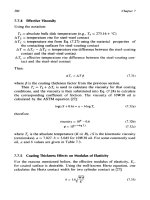
In
classified areas, breathers
and
drains must
be
explosion-proof. Figure
17-28
shows
typical
explo-
sion-proof
breathers
and
drains.
Space
heaters,
particularly
in
electrical
motors
and
generators
which
may
be
idle
for
significant
periods
of
time,
can
also help prevent
the
accumulation
of
moisture. Space heaters installed
in
classified areas
must
operate
at
temperatures below "high temperature" devices.
To
retard corrosion
and to
facilitate
future
maintenance (e.g., allow
the
non-destructive
removal
of
threaded junction
box
covers),
all
threaded
connections should
be
lubricated with
an
antiseize compound which will
not
dry out in the
environment.
If
lubricant
is
applied
to the
threaded
(or
flanged)
portion
of
covers
of
explosion-proof enclosures,
the
lubricant
must
have been tested
and
approved
as
suitable
for flame
path
use.
It is
cautioned
that some lubricants contain silicone, which
will
poison most
catalytic
gas
detector sensors
and
should
not be
used near
gas
detectors.
Figure
17-28.
Standard
explosion-proof
drains
and
breathers.
(Courtesy
of
Crouse-
Hinds
Electrical Construction
Materials,
a
division
of
Cooper
Industries,
Inc.]
Electrical
Systems
547
Many
materials
are
subject
to
deterioration
by
ultraviolet light (UV),
particularly many
of the
"plastics"
and
fiberglass materials. Fiberglass
materials
for
outside
use
should
be
specified
as
UV-stabilized,
and
most
plastics installed outdoors should
be
carbon-impregnated
(black
in
color).
It is
particularly
recommended that
plastic
cable
ties,
which
secure cables
in
cable trays,
be
carbon-impregnated
if
installed outdoors.
In
areas where
electrical
equipment
is
exposed
to
contaminants,
the
selection
of
equipment whose contacts
are
oil-immersed
or
hermetically
sealed
can
increase
reliability
and
equipment
life. Similarly, providing
environmentally-controlled equipment rooms
can
greatly increase equip-
ment
life
at
locations where contaminants
are
prevalent.
In
offshore
and
other
areas exposed
to
salt, type
316
stainless steel
is
often
preferred over
types
303 and
304, which will
pit
with time. Likewise,
in
similar
loca-
tions,
equipment;
fabricated
from galvanized
steel
will
corrode
much
more
rapidly than equipment hot-dip
galvanized
after
fabrication.
ELECTRICAL
STANDARDS
AND
CODES
American National Standards Institute
(ANSI)
1430 Broadway
New
York,
NY
10018
C84.1
Voltage Ratings
for
Electrical Power Systems
and
Equipment
(60 Hz)
Y
14.15
Electrical
and
Electronics Diagrams
American
Petroleum
Institute
(API)
2101
L
Street,
NW
Washington,
DC
20037
RP 14F
Recommended Practice
for
Design
and
Installation
of
Elec-
trical Systems
for
Offshore Production Platforms
RP
500
Recommended Practice
for
Classification
of
Locations
for
Electrical
Installations
at
Petroleum Facilities Classified
As
Class
I,
Division
1 and
Division
2,
American Society
of
Heating,
Refrigerating
and Air
Conditioning Engi-
neers, Inc.
(ASHRAE)
1791
Tullie Circle,
NE
Atlanta,
GA
30329
ASHRAE
Fundamentals Handbook
548
Design
of
GAS-HANDLING
Systems
and
Facilities
British
Standards
Institute
(BSI)
Newton
House
101
Pentionville Road
London,
Nl
9ND
or,
c/o
American National Standards Institute,
1430 Broadway
New
York,
NY
10018
BS5501
Part
1,
General Requirements
Part
2, Oil
Immersion
"o"
Part
3,
Pressurized Apparatus
"p"
Part
4,
Power Filling
"q"
Part
5,
Flameproof Enclosure
"d"
Part
6,
Increased
Safety
"e"
Part
7,
Intrinsic
Safety
"i"
BS5345
Code
of
Practice
in the
Selection,
Installation,
and
Mainte-
nance
of
Electrical Apparatus
for Use in
Potentially Explo-
sive
Atmospheres (Other than Mining Applications
or
Explo-
sive
Processing
and
Manufacture)
Canadian
Standards
Association (CSA)
178
Rexdale Boulevard
Rexdale,
Ontario
M9W
1R3
Canada
C22.1,
Part
I
Canadian Electrical Code
C22.2,
No. 30
Explosion-proof Enclosures
for Use in
Class
I
Haz-
ardous
Locations
C22.2,
No. 14
Motors
and
Generators
for Use in
Hazardous Loca-
tions
C22.2,
No. 157
Intrinsically Safe
and
Nonincendive Equipment
for
Use
in
Hazardous Locations
C22.2,
No. 174
Cables
and
Cable Glands
for Use in
Hazardous Loca-
tions
C22.2,
No. 213
Equipment
for Use in
Class
I,
Division
2
Hazardous
Locations,
A
Guide
for the
Design, Construction
and
Installation
of
Electrical Equipment; John
Bossert
and
Randolph
Hurst
Electrical
Systems
549
European
Committee
for
Electrotechnical Standardization
(CENELEC)
Rue
Brederode
2
Boite
No. 5
8-1000Bruxelles
Beligique
EN50014
General Requirements
EN50015
Oil
Immersion
"o"
EN50016
Pressurized Apparatus
"p"
EN50017
Power Filling
"q"
EN50018
Flameproof Enclosure
"d"
EN50019
Increased
Safety
"e"
EN50020 Intrinsic Safety
"i"
EN50039
Intrinsically
Safe
Electrical
Systems
"i"
Factory>
Mutual
Research Corporation
(FM)
1151
Boston-Providence Turnpike
Norwood,
MA
02062
Std.
3615 Explosion-proof Electrical Equipment
Std. 3610 Electrical Intrinsically Safe Apparatus
and
Associated
Apparatus
for Use in
Class
I, II, and
III, Division
1,
Haz-
ardous Locations
Illuminating
Engineering
Society
(IBS)
345
East 47th Street
New
York,
NY
10017
RP-7
American National Standard Practice
for
Industrial Lighting
IBS
Lighting Handbook
Institute
of
Electrical
and
Electronic Engineers
(IEEE)
345
East 47th Street
New
York,
NY
10017
Std.
45
Recommended Practice
for
Electrical Installation
on
Ship-
board
Std.
142
Recommended
Practice
for
Grounding
of
Industrial
and
Commercial
Power Systems
Std.
141
Recommended Practice
for
Electric Power Distribution
for
Industrial
Plants
550
Design
of
GAS-HANDLING
Systems
and
Facilities
Std.
303
Recommended
Practice
for
Auxiliary Devices
for
Motors
in
Class
I,
Groups
A, B, C, and D,
Division
2
Locations
RP
446
Recommended
Practice
for
Emergency
and
Standby Power
Systems
for
Industrial
and
Commercial Applications
Instrument
Society
of
America
(ISA)
P,
O.
Box
12277
Research Triangle Park,
NC
27709
S5.1
Instrumentation Symbols
and
Identification
RP12.1
Recommended
Practice
for
Electrical
Instruments
in
Haz-
ardous
(Classified) Atmospheres
S12.1
Intrinsic
Safety
S12.4
Instrument Purging
for
Reduction
of
Hazardous Area Classi-
fication
RP12.6
Installation
of
Intrinsically
Safe
Instrument Systems
for
Haz-
ardous (Classified) Locations
5.2,12
Electrical Equipment
for Use in
Class
I,
Division
2
Haz-
ardous
(Classified) Locations
512.13
Part
I,
Performance Requirements, Combustible
Gas
Detec-
tors
RP12.13
Part
II,
Installation, Operation,
and
Maintenance
of
Com-
bustible
Gas
Detection Instruments
SI2,15
Part
I,
Performance Requirements, Hydrogen Sulfide
Gas
Detectors
(Draft
Standard)
RP12.15
Part
II,
Installation,
Operation,
and
Maintenance
of
Hydro-
gen
Sulfide
Gas
Detection Instruments
(Draft
Standard)
S51.1
Process Instrumentation Terminology
S71.01
Environmental Condition
for
Process
Measurement
and
Con-
trol Systems: Temperature
and
Humidity
Electrical Instruments
in
Hazardous
Locations,
Ernest
C.
Magison, 1978
Electrical
Safety Abstracts. Edited
by
Alfred
H.
McKinney
and
Harry
G.
Conner
National
Electrical
Manufacturers
Association
(NEMA)
2101
L
Street,
NW
Washington,
DC
20037
ICS
2
Standards
for
Industrial Control Devices, Controllers
and
Assemblies
Electrical
Systems
551
ICS
6
Enclosures
for
Industrial Controls
and
Systems
MG 1
Motors
and
Generators
MG 2
Safety
Standard
for
Construction
and
Guide
for
Selection,
Installation,
and Use of
Electric Motors
and
Generators
MG
10
Energy Guide
for
Selection
and Use of
Polyphase Motors
VE 1
Cable Tray Systems
National
Fire
Protection
Association
(NFPA)
Batterymarch
Park
Quincy,
MA
02269
No.
30
Flammable
and
Combustible Liquids Code
No. 37
Standard
for the
Installation
and Use of
Stationary Com-
bustion Engines
and
Turbines
No.
70
National
Electrical
Code
No.
77
Recommended Practice
on
Static
Electricity
No.
78
Lightning Protection Code
No.
321
Basic Classification
of
Flammable
and
Combustible Liquids
No.
325M Fire Hazard Properties
of
Flammable Liquids, Gases,
and
Volatile
Solids
No.
493
Standard
for
Intrinsically
Safe
Apparatus
and
Associated
Apparatus
for Use in
Class
I, II, and
III, Division
1
Haz-
ardous
Locations
No. 496
Standard
for
Purged
and
Pressurized Enclosures
for
Elec-
trical
Equipment
in
Hazardous (Classified)
Locations
No.
497
Recommended Practice
for
Classification
of
Class
I
Haz-
ardous
Locations
for
Electrical Installations
in
Chemical
Plants
No.
497M Classification
of
Gases, Vapors
and
Dusts
for
Electrical
Equipment
in
Hazardous
(Classified)
Locations
Underwriters
Laboratories, Inc.
(UL)
33
Pfingsten
Road
Northbrook,
IL
60062
UL
58 An
Investigation
of
Fifteen Flammable Gases
or
Vapors
with
Respect
to
Explosion-proof
Electrical
Equipment
UL
58A An
Investigation
of
Additional Flammable Gases
or
Vapors
with
Respect
to
Explosion-proof Electrical Equipment
UL
58B An
Investigation
of
Additional
Flammable
Gases
or
Vapors
with
Respect
to
Explosion-proof Electrical Equipment
552
Design
of
GAS-HANDLING
Systems
and
Facilities
UL
595
Standard
for
Marine-type Electric Lighting Fixtures
UL674
Electric Motors
and
Generators
for Use in
Hazardous
Loca-
tions, Class
I,
Groups
C and D, and
Class
II,
Groups
E, F,
andG
UL
698
Safety
Standard
for
Electric Industrial Controls
Equipment
for Use in
Hazardous
(Classified)
Locations
UL 844
Standard
for
Electric
Lighting
Fixtures
for Use in
Haz-
ardous
Locations
UL
877
Circuit-Breakers
and
Circuit-Breaker
Enclosures
for Use in
Hazardous
Locations, Class
I,
Groups
A, B, C, and
D,
and
Class
II,
Groups
E, F, and G
UL
886
Outlet Boxes
and
Fittings
for Use in
Hazardous Locations
in
Class
I, II, and
III,
Division
1,
Hazardous
Locations
UL
1010
Receptacle—Plug
Combinations
for Use in
Hazardous
(Classified) Locations
UL
1203
Explosion-proof
and
Dust-ignition-proof Electrical
Equip-
ment
for Use in
Hazardous
Locations
UL
1604
Electrical Equipment
for Use in
Hazardous Locations, Class
I and II,
Division
2,
and
Class
III,
Divisions
1 and 2
United
States
Code
of
Federal
Regulations
c/o
U.S.
Government Printing
Office
Washington,
D.C.
20402
Title
29,
Occupational
Safety
and
Health Standards,
Subpart
S,
Part
1910 Electrical
Title
30, Oil and Gas and
Sulfur
Operations
in the
Outer
Part
250
Continental Shelf
Title
33,
Subchapter
C,
Aids
to
Navigation Part
67
Title
46,
Shipping Subchapter
J,
Electrical Engineering, Parts
110-113
(United States
Coast
Guard, CG259)
Index
Absorbers,
gas
processing plants,
244
exchangers,
rich/lean,
189
Absorption process, glycol,
196-204
flash
drums,
187
Absorption/lean
oil
plants,
244—246,
processes,
162-166
249-250
reboilers,
162, 187-188
Acetylene,
504
solution
purification,
189-190
Acid
compounds, limitations,
153
strippers,
188
Acid
gas
strippers, overhead condensers,
188-189
correction factor,
198-199
systems, corrosion
control,
190
nature
of,
151
systems, design procedures,
185-190
treating
process selection,
179-180
systems, materials,
190
treating,
151-194
units,
91
Adiabatic expansion,
113
Ammonium thiosulfate,
174
Adsorption,
228
Annunciation systems,
405-406
After-coolers,
257
API,
See
American
Petroleum
Institute.
Air
compressors, turbines,
479-486
Arctic Region,
487
Air
deflectors,
514
Areas, classified.
See
Classified areas,
Air
pollution,
487-492
Arsenic activators,
169
Alarms,
513,514
ASME.
See
American Society
of
Alcohol,
103
Mechanical Engineers.
Alkanolamine
activators,
169
Asphyxiation,
393
Allied
Chemical Company,
172
ASTM,
138,
448
Aluminas,
236
American
National Standard Institute Backflow protection,
366
(ANSI),
118,
119,
248,
396,448,
449,
Backflow,
465
532,
547,
548
Back-pressure,
111
American
Petroleum Institute,
10,
Balanced-bellows relief valves,
363
118-119,
320-321,
356, 357, 387,
Bath heaters.
See
Indirect
fired
heaters.
392,
401
-405,
430,448,
451,
500,
Batteries
504,
509, 510, 513, 532, 533,
547
charger system,
517
American Society
of
Heating, rechargeable,
517
Refrigerating,
and Air
Conditioning types,
517-520
Engineers,
Inc.
(ASHRAE),
547
Battery chargers,
517,518
American
Society
of
Mechanical Bearings, compressor,
296-298
Engineers
(ASME),
52,
327, 328,
Bernoulli's
Law,
255
331.
333.
356,
396
Blanket
gas
systems, inert,
165
Amine
Block valves,
375-376, 462,
465
absorbers,
185-186
Blowby.
See Gas
blowby.
circulation
rates,
186-187
Slowdown
valve,
279,
284
coolers,
189
Blowout preventers,
514
553
Booster compressors, 254,
286
Cathrates,
92
Borate activators,
169
CFR.
See
U.S. Code
of
Federal
Bottoms
Regulations.
liquids,
138,
247
Channel valves, 300,
301
temperature,
141,247
Check valves,
366,465
Brake
horsepower,
268,475
Chemical solvent process,
161-172.
See
Brayton
air
cycle,
479
also Amines; Amine process;
Hot
Breathers,
546
potassium carbonate process;
Breathing
apparatus,
513
Carbonate systems, proprietary.
British
Gas
Corporation,
175
Chemical solvent process, LOCAT use,
British
Standards Institute (BP1),
548 175
Bubble
caps, 142,
200
Chiller, refrigeration
process,
247
Bums,
393
Chokes,
2,
92-93,114,440,461,462
Busway,
gasketed,
533
Choking,
100-103
Butane,
5,
94,
241,
246,
250-251
Circuit
Butanes-plus,
250
capacitance,
524
inductance,
524
Cable
systems, 494,
533-534
Classified
areas,
461,
500-513.
See
also
Cable, power limited tray,
533
Hazardous areas.
Canadian Standards Assn. (CSA),
548
devices,
518
Capacity
control devices, hydraulic lines,
461
compressor,
302
motors,
461,
525,
542
Carbon
dioxide piping,
451
acid
formation,
195
welding,
461
amine
strippers,
188
wireline
units,
461
atmospheric
release,
166-172
wiring,
529-541
chemical
solvents and,
161-172
Claus
process,
173
iron sponge process,
157
Co-current
flows, gas
line,
200
limitations,
153
COj.
See
Carbon dioxide.
LOCAT process,
174
Coils, indirect heaters
molecular
sieves and,
160-161
diameters,
117-118
natural
gas
impurities,
4
length,
119-120
permeable membranes and,
178-179
sizing,
116-120
physical solvent processes,
169
temperatures,
116-117
pseudo
critical
pressures
and
wall thickness,
118-119
temperatures,
41
Cold
Bed
Absorption (CBA)
removal
from
natural gas,
91,151
process,
174
Carbon
disulfide,
163-166,
170,
171
Combustion
Carbon monoxide, engines,
487—490
gas
turbine,
479,482
Carbonate systems, proprietary,
168
internal, 469.
See
also Engines.
Carbonic acid,
4,151
Combustors,
479
Carbonyl
sulfide
(COS),
163-166,
170, Communications, power supply,
517
171
Components
Carburetion,
475-477
compressors,
286-307
Casing vapor recovery
heavy,
137
compressors,
254
intermediate,
111,
130-131,135,137,149
Casinghead
gas
compressors,
254
light,
111,
131-132,
135,
137
554
Compression kinetic,
255
engine,
470
lubrication
immersion
heaters,
316
gas,
2
lubrication,
299,
313-317
Compressor
natural
gas,
461
buildings,
514
offshore
installations,
320
horsepower,
determining,
272-276
packing lubrication system,
316
ratio,
overall,
253
packing,
298-300
specifying,
270-272
pipe sizing,
317-319
stages, determining,
272-276
pipeline booster
use,
262
use,
oil and gas
fields,
254
piston displacement,
308
Compressors piston wear bands,
296
acoustical
pulsations,
317-319
pistons
and
piston
rods,
296
balanced
opposed
frames, 286
positive-displacement,
255
bearings,
296-298
reciprocating,
3,
255-264,286-326
booster,
254, 276,
286
high-speed,
258-259
capacity
control devices,
302
low-speed,
259-264
casinghead
gas,
254
process considerations,
276-280
centrifugal,
3,
267-270,
286
rod, 294,
310-311
centr
i
fugal
proces
s
considerations,
rotary
,3,255
281-285
screw,
255,
266-267
centrifugal,
stonewalling,
280-281
separable units defined,
258
centrifugal,
surge control,
280-281
single-acting cylinders,
289,
307
components,
286-307
types,
255-270
crankshafts,
294
valve
unloader types,
303
crossheads.
294
valve velocity,
301-302
cylinder
capacity,
307
valves,
300-302
cylinder
clearance,
305-307
vane,
3,
255,
264-266
cylinder
cooling,
312-313
vapor
recovery,
204,
276
cylinder
liners,
291
vibration,
317-319
cylinder
lubrication system,
316
volumetric efficiency,
308
cylinder
MAWP,
290
Condensate,
3,
111
cylinder piston displacement,
308
Condensate stabilization,
3,
130-150
cylinder
sizing,
307-310
Condensate stabilizers
cylinders,
268
cold feed,
111,
134,
136-137,
distance
pieces,
293-294 149,
249
double-acting
cylinders,
289,
307
definition,
134
engine-driven,
393
design,
137
flash
gas,
253,
276
gas-producing plant,
as, 149
flexibility,
310
LTX
unit
as, 149
foundation
design,
319
reflux with,
149
frames,
287-289
system,
133
gas
lift,
254, 262, 276,
278
units,
247
general,
253-285
Condensers
heads,
461
amine
stripper overhead,
188
Helical-Lobe,
266-267
glycol
reflux,
202
industry
specifications,
320-321
Conditions,
future
operating,
447
integral
units,
258, 259,
288
Conduction,
8-10,
14, 82
555
Conductivity,
thermal
amine
solutions,
162
hydrocarbon
liquids,
20
contactors,
198
natural
gas,
20
trayed/packed
towers,
185
proportionality
constant,
9,
10
Crankshaft, compressor,
294
Conduit
Crossheads,
compressor,
294
fittings,
535
Cru.de
oil
supports,
535
fire
tubes,
393
systems,
531-535
high-viscosity,
446
Contact
towers
gas
processing stabilizers,
245
plants,
244 oil
streams,
130
Contactor pressure, glycol process,
195
stabilization,
130
Contactors treating,
109
glycol process,
198
Cryogenic
sizing,
213-217
distillation,
178
tray
numbers,
206-207
gas
plants,
5,
196,
229,
231-232,
Containment,
389
248-249
Contaminants,
522
CS
2
.
See
Carbon disulfide.
Contaminants,
gas
turbines
and,
486-487
CVR
units.
See
Casing vapor recovery
Control
rooms,
524
compressors.
Control stations,
465-466
Cylinder
Convection,
8,9-10,14,
28, 82
capacity, defined,
307
Coolers, aerial,
74
clearance,
305-307
Cooling
cooling systems,
compressors,
312-313
distillation tower with
reflux,
136
lubrication systems, compressors,
lubricating systems,
compressor,
313-317
312-317
s
izi
ng,
compressors,
307-31.0
Cord,
flexible
electrical,
533
throughput capacity,
309
Corrosion Cylinders
allowance, pressure
vessels,
333
compressors.
See
Compressors,
amine
systems,
190
cylinders.
condensed water,
195
engine,
470,
475
conduits,
534
electrical
systems,
545-547
De-butanizers,
250
gas
sales
and,
151
De-ethanizers,
247,250
gels,
236
De-methanizers,
247-250
heat
exchangers,
72
De-propanizers,
250-251
inhibitors,
446
DBA.
See
Diethanolamine.
onshore
facilities,
546
Dehydration
piping,
448
cooling and,
2
protection.
See
Acid gases. definition,
195
resistance,
542
general,
195,
240
rupture
discs
and 367
glycol,
91
stressed steel
and,
164-165
hydrate formation, preventing,
92-93
COS.
Sec
Carbonyl
sulfide.
inhibitors, kinetic
and
anti-
Counter-currenl
flow
agglomerators,
107-108
absorbers,
167,
169
thermodynamic,
103-107
556
specifications,
4
Drains,
liquid
seals,
465
systems,
solid
bed,
195,228-240.
See
Drains,
open,
465
also
Solid
bed
process.
Drip pans,
389
water
vapor removal,
100
Dust,
combustible,
500
See
also Hydrates; Hydrate formation.
Delta-connected
electrical
systems,
496
Electrical devices, types,
518-529
Demister
pads,
487
Electrical equipment, contaminants
and,
Desiccant
tower.
See
Solid
bed
process,
547
two-tower
unit.
Electrical shock,
393
Desiccants
Electrical shorts,
392
definition,
228
Electrical systems
selection,
235-236
corrosion
and, 545-547
Detectors,
fire
and
gas,
517
deltas,
496
Devices design,
493
hermetically
sealed,
522,
547
four-wire,
496
high-temperature,
518,
539 gas
facilities,
493-552
nonincendive,
523
three-phase,
496
types
of
electrical,
518-529
three-wire,
496
Dew
point,
4,
92,98,
101, 195,
246
wyes,
496
Diethanolamine
(DEA),
163,
166
Emergency shut-down stations,
405
Diethanoiamine
(DEA) systems,
165-166,
Emulsion heating,
121
185,
186,
190
Enclosures
Diethylene
glycot
(DEG),
103,
204
equipment,
545
Diglycolamine
(DGA),
166
explosion-proof,
521-522
Diglycolamine systems,
166
hermetically
sealed,
525
Diisopropanolamine
(DIPA),
166,171
purged,
523-524
Diisopropanolamine
systems,
166
weather-tight,
521
Dikes, retaining,
389
Energy, radiant,
10
DIPA.
See
Diisopropanolamine. Engine manifolds,
393
Direct
fired heaters,
133,481
Engines
Discharge aspirated,
475
blocked,
356
compression,
470,472
check valves,
284
cylinder,
470,
475
coolers,
280,
285
diesel,
477
shut-down
valves, discharge check,
279,
environment
and,
487-492
284
four-cycle,
468-^70,
473-475
Distillation
gas
turbine,
477-487
process, acid
gas,
178
high-speed,
474
towers,
247
intermediate-speed,
474
cold feed,
134-136
noise pollution,
492
design,
251-252
piston-ported,
472
reboiler use,
121
pistons,
468-473
reflux
with,
136-137
reciprocating,
468,
487
Double-pipe heat exchangers,
65
safety
devices,
477
Downcomers,
134,
185
shut-down system,
477
Drains,
464-465
slow-speed,
474
557
Engines
(continued)
Film
coefficient
spark-ignition,
477
external,
14-15
speed,
474
inside,
15-28
supercharged,
475
internal,
14—15
two-cycle,
470-475
outside,
28-33
Enthalpy,
100,113
shell-and-tube,
37
Equipment
rooms,
547
overall,
line
heaters,
120
Escape,
394
Filter separators,
201
ESD.
See
Emergency shutdown stations. Filters
Ethane,
5,
111,
130,
135,241,
247-251
charcoal,
201
Ethylene,
503
sock,
201
Ethylene
glycol
(EG),
103,204,
247
Filtration, inlet
air,
487
European
Committee
for
Electrotechnical
Fire detectors,
395-396,
517
Standardization,
548-549
Fire tubes
Exhaust
area,
44-46
engine,
393,470
glycol reboilers,
201
turbine,
393,475
hazard,
362,
395
Exhaust
manifolds,
461
heat transfer,
44-46
Expansion
minimum diameter,
45
bottles,
461
size, indirect heaters,
115
valves,
248
Fire water pumps,
classified
Explosion-proof
areas,
461
breathers,
546
Fire, pressure relief
and,
357
conduit
fittings,
535.539
Fire/explosion,
389,
392,394-396
connections,
531
Firefighting equipment,
393
defined,
521-522
Fittings
drains,
546
classification,
330,441
enclosures,
521,
524-525,536-540
conduit sealing,
539
junction
boxes,
535
couplings,
451
lighting,
529
pressure
classes,
441-445
Explosions,
See
Fire/Explosion.
seal installation,
540-541
Explosions, conduit,
532,
534
sealing,
534
tables,
449
Facilities,
gas.
See Gas
facilities. target tees,
461
Factory
Mutual Research Corporation tees,
451
(FM),
549
Flame
arrestors,
395
Fail-safe
Flange protectors,
462-463
electrical,
517
Flare system,
279,375
gas
detection,
513-515
Flare valves,
276-278,
282
Failure
Mode
Effect
Analysis (FMEA), Flares,
10
396-401
Flash
gas
compressor,
253
Feed Stream,
137
Flash
separator,
132
Ferric oxide chips,
180-181,
184
Flash tanks,
165
Ferric oxide,
157
Flashing,
514
Fiberglass piping, reinforced,
451
Flow
Fibers,
ignitible,
500
co-current.
See
Co-current
flow.
558
counter-current.
See
Counter-current
flow
rate, relief valves,
370
flow.
gravity,
97
criteria,
erosional,
117-118
heating value,
4
high-pressure,
445
leaks, 392, 393,
395
laminar,
446
lift
compressors,
254
low-pressure,
445
permeation
process,
178-179
rates,
gas
turbine,
482
processing plant,
149
tube,
laminar,
15
processing processes, choice
of,
tube, turbulent,
15
249-252
two-phase
rates,
445
processing, definition,
241
Flow
lines,
445,
451
processing, methods,
244—249
Fluid composition,
446
processing, objectives,
244
Fluid
density,
oil and gas
stream,
117
processing, refrigeration method,
Fluid
Met
temperature,
17
246-248
Fluid, production,
446
production
facilities,
7,47,
65, 522
Fluor
Econamine
process,
166,185
reservoirs,
2
Fluor
Solvent
process,
170-171
sales,
3,111,151,195
FMEA.
See
Failure
Mode
Effect
Analysis. scrubbers, integral,
185
Forced-air heat exchangers,
74-79
stream,
111
Fouling, effects,
15
stream, heating,
109
Fractionation systems,
250
stream,
liquids,
130
Fractionation,
249
sweetening process, methods,
156—179.
Frames,
compressors,
287-289
See
also
the
various individual
Free water,
93
methods.
Freon,
246, 247,
248
sweetening process,
selection,
179—180
Fuel
flow,
carburetion,
476
sweetening unit,
LOCAT
as,
174-175
Fuel
injection,
475—477
transmission companies,
3
Fuel
injection valves,
473
turbines,
477-487
Furnace, reaction,
174
ambience and,
482
Furnaces,
82,
109
environment and,
487,488,491
multi-shaft,
483-486
Galvanic
action,
546
single shaft,
483-486
Galvanized steel,
547
velocity head,
255
Gas
well pressure,
131-132
blankets,
392
well
streams,
48
blowby,
356-357,464
Gas
Processors
Suppliers
Assn.,
33,41
compression,
3,
131.
See
also
Gas/glycol
heat exchangers,
201
Compressors. Gases
condensate,
130 flammable,
500,
523
dehydration.
See
Dehydration.
toxic,
513-515
detectors,
395-396,461,
513-515,
517, Gasoline,
250
546
Generating stations,
495-496
expansion,
temperature
drop,
100-103
Generators
facilities,
3
classified areas,
461
fields,
130,
253
continuous duty,
496
fields,
compressor use, 254,
262
engine-driven,
493
559
Generators
(continued)
See
also Classified
areas,
hazardous
areas,
461,
525
Headers,
360, 366,
375
sizing,
495
Heat
standby,
494,496
capacity,
40
TEFC,
525
duty,
phase changes,
43
turbine,
494
exchangers,
2,47-91.
See
also
Shell-
units,
493
and-tube
exchangers; Double-pipe
German
Lurgi
Company,
172
exchangers;
Plate-and-frame
Giycoi
exchangers; Bath-type exchangers;
circulation
rate,
211-212
Forced-air exchangers;
and
Direct
concentration,
208-209
fired
exchangers.
'
dehydration process, description, exchangers, bath type,
47. See
also
198-204
Direct fired
and
Indirect
fired,
dehydration,
91,196-228
exchangers, cryogenic plants,
248
/glycol
heat exchanger,
202
exchangers, glycol
process,
204,
206
reboilers,
heat duty,
217-218
exchangers, glycol
reboilers,
217-218
reboilers,
pressure,
210-211
exchangers, hairpin style,
65
reboilers,
temperatures,
209-210
exchangers,
indirect
bath,
48
reconcentration
systems,
201
exchangers,
shell-and-tube,
48-64.
See
reconcentration,
definition,
198
also Shell-and-tube
exchangers,
regeneration,
2,198
exchangers, U-type,
65
stripping stills, temperatures,
212-213
exhaust, waste,
47,
113
systems,
sizing,
213-218
flow
rate,
9
Glycois,
103
loss, atmospheric,
43-44
Governors,
476
medium exchangers,
133
Ground
loops,
515,517
medium
fluids,
47
Grounding
medium
fluids,
furnaces,
82
discussion,
515-517
medium
fluids,
specific heat,
23
equipment,
516
medium
fluids,
thermal conductivity,
24
lightning,
516
medium
fluids,
viscosity,
24
methods,
517
mediums,
water-glycol,
141
offshore
,517
recovery,
481
static
electricity,
516
transfer
coeficient,
overall,
14—15,
supply
system,
515-516
33-34
transfer mechanisms, 7-35
H
2
S,
See
Hydrogen sulfide. transfer
processes,
11
Hammering, hazard,
392
transfer rate.
See
Heat
flow
rate.
Hammerschmidt
equation,
105
transfer theory,
7-46
Hazard
transfer,
overall
temperature difference,
analysis,
401
11-14
tree,
387-394,
395
Heat-stable
salts,
164
Hazardous area classification Heater treaters,
393
European,
503—504
Horsepower.
See
Brake horsepower;
U.S.
and
Canada,
500-513
Friction
horsepower; Indicated
Hazardous
areas horsepower.
device installation,
524-529
Hot
potassium carbonate process,
167-168
motors,
461,
525-529,
542 Hot
surface hazards,
461
560