Electric Machinery Fundamentals (Solutions Manual) Part 1 pdf
Bạn đang xem bản rút gọn của tài liệu. Xem và tải ngay bản đầy đủ của tài liệu tại đây (120.02 KB, 10 trang )
Chapter 5: Synchronous Generators
5-1.
At
a location
in
Europe, it
is
necessary
to
supply 300
kW
of 60-Hz power. The only power sources
available
operate at
50
Hz.
It
is
decided to
generate the power by means
of a
motor-generator set
consisting of a synchronous motor
driving a synchronous generator. How
many
poles
should
each
of
the
two machines have in
order to convert
50-Hz power
to 60-Hz power?
S
OLUTION
The speed of a synchronous machine is
related
to its frequency by
the
equation
m
n
=
120
f
e
P
To make a
50
Hz
and
a 60 Hz machine have the same mechanical speed so that they can be coupled
together, we see that
120
(
)
50 Hz
120
(
)
60 Hz
=
=
s
n
ync
P
P
1 2
2
P
6
12
=
=
P
1
5
10
Therefore, a 10-pole synchronous
motor
must
be
coupled to a 12-pole
synchronous generator
to accomplish
this frequency
conversion.
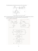
5-2.
A
2300-V
1000-kVA
0.8-PF-lagging
60-Hz
two-pole
Y-connected
synchronous
generator
has
a
synchronous reactance of 1.1
&
and an
armature resistance
of 0.15
&
. At 60 Hz, its friction and windage
losses are 24 kW, and its core losses are 18 kW. The field circuit has
a
dc
voltage
of
200
V,
and
the
maximum
I
F
is 10 A. The resistance of the field circuit is adjustable
over
the
range
from
20
to
200
&
.
The OCC of this generator is shown
in Figure P5-1.
(a)
How much field current is required to make
V
T
equal to 2300 V when the generator is running at no
load?
(b)
What
is the internal generated voltage
of
this machine at
rated conditions?
(c)
How much
field current
is required to make
V
T
equal
to 2300
V when the generator is running at
rated
conditions?
(d)
How much power and
torque must the generator’s prime mover be
capable
of
supplying?
(e)
Construct a capability
curve for this generator.
Note:
An electronic version of this open circuit
characteristic can
be
found
in
fil
p51_occ.dat
,
which
can
be
used
with
MATLAB
programs.
Column
1
contains
field
current
in
amps, and column 2 contains
open-circuit termina
voltage in
volts.
109
S
OLUTION
(a)
If the
no-load
terminal
voltage is 2300 V, the required field current can be read directly from the
open-circuit characteristic. It is 4.25
A.
(b)
This generator is
Y-connected, so
generator is
I
L
=
I
A
. At rated conditions,
the line and phase current in
this
P
I
I
=
=
1000
k
=
VA
251
=
A
at an angle
of
–36.87
°
3
3
(
)
2300
V
A L
L
V
=
=
. The internal generated voltage
of
the
machineThe phase voltage of this
machine
is
⎞
T
/
V
V
3
1328 V
is
=
+
E
V
+
I
I
A
A
⎞
A
S
A
R
jX
1328
0
(
0.15
)(
)
251
36.87
A
(
1.1
)(
)
251
36.87
A
E
A
=
°
+
&
°
j
+
&
°
E
A
1537
7.4
V
=
°
(c)
The
equivalent open-circuit
terminal
voltage corresponding to an
E
A
of 1537 volts is
(
)
T
V
,oc
3
1527 V
2662 V
=
=
From the OCC, the required field current is 5.9
A.
(d)
The input power
to this generator is equal to
the
output power plus losses.
The
rated output
power is
(
)(
)
OUT
P
1000 kVA
0.8
800 kW
=
=
2
(
=
=
)
2
(
)
&
=
CU
3
A
A
P
I
3
R
251 A
0.15
28.4 kW
F&
P
=
W
24 kW
110
co
P
re
=
18 kW
st
P
ray
=
(assumed 0)
=
+
+
+
+
=
IN
OUT
P
P
CU
P
F&W
P
core
P
stray
P
870.4 kW
Therefore the prime mover
must
be capable of supplying 175 kW.
Since the generator is a two-pole
60 Hz
machine, to must be turning
at 3600
r/min.
The required torque
is
⎮
=
IN
P
=
175
2.
kW
=
465
N
⊕
m
⎤
(
)
3600
r/min
⎧
1
min
⎟⎧
2
rad
⎟
APP
m
⎣
⎞⎣
⎞
⎨
60
s
⎠⎨
1
r
⎠
(e)
The rotor current limit of the capability curve would be
drawn from an origin
of
3
V
2
3
(
)
1328 V
2
Q
=
⎞
=
=
4810 kVAR
S
X
1.1
&
The radius of the rotor current
limit is
3
3
(
)
1328 V
(
1537 V
)
D
⎞
A
V
E
5567 kVA
=
=
=
S
X
E
1.1
&
The stator
current limit is a circle at
the
origin of
radius
3
3
(
1328
V
=
=
⎞
A
S
V
I
)(
251
A
)
1000 k
=
VA
A MATLAB program that plots this capability diagram is shown below:
% M-file: prob5_2.m
% M-file
to
display a
capability curve for a
% synchronous generator.
% Calculate
the waveforms for times from 0 to 1/30 s
Q = -4810;
DE =
5567;
S = 1000;
% Get
points for stator current limit
theta
= -95:1:95;
% Angle in degrees
rad =
theta
* pi /
180;
% Angle in radians
s_curve = S
.*
( cos(rad) +
j*sin(rad) );
% Get
points for rotor current
limit
orig = j*Q;
theta
= 75:1:105;
% Angle in degrees
rad =
theta
* pi /
180;
% Angle in radians
r_curve = orig
+ DE .* (
cos(rad)
+ j*sin(rad)
);
% Plot the capability
diagram
figure(1);
plot(real(s_curve),imag(s_curve),'b','LineWidth',2.0);
hold on;
plot(real(r_curve),imag(r_curve),'r ','LineWidth',2.0);
% Add
x and
y axes
111
plot( [-1500
1500],[0 0],'k');
plot( [0,0],[-1500 1500],'k');
% Set
titles and axes
title
('\bfSynchronous Generator Capability
Diagram');
xlabel('\bfPower (kW)');
ylabel('\bfReactive Power (kVAR)');
axis( [
-1500
1500 -1500 1500] );
axis square;
hold off;
The resulting
capability diagram
is shown below:
5-3.
Assume that the
field current
of
the
generator
in Problem 5-2
has been
adjusted to a value
of
4.5 A.
(a)
What
will
the
terminal
voltage
of this generator be
if it is connected to a
-connected load with an
impedance of
20
30
°
&
?
(b)
Sketch the phasor diagram
of this generator.
(c)
What
is the efficiency of the generator at these conditions?
(d)
Now assume that another identical
-connected load is to
be paralleled with the first
one.
What
happens to the phasor diagram for the
generator?
(e)
What
is the new terminal
voltage after the load has been added?
(f)
What must be done to
restore the
terminal
voltage to its
original
value?
S
OLUTION
(a)
If the field current is 4.5 A, the open-circuit terminal voltage will
be about 2385
V,
and
the
phase
voltage in the generator will
be
2385
/
3
=
1377 V
.
The load is
-connected with three impedances
of
20
30
°
&
.
From the
Y-
transform, this load
is equivalent
to
a
Y-connected
load
with
three
impedances
of
6.667
30
°
&
.
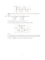
The
resulting
per-
phase equivalent circuit is
shown below:
112
0.15
&
j
1.1
&
I
A
+
+
A
E
-
⎞
V
Z
6.667
3
0°
-
The magnitude of the phase current
flowing
in this generator is
I
E
A
1377 V
=
=
1377 V
186 A
=
=
A
+
+
0.15
1.1
+
6.667
+
30
1.82
°
A S
R
jX
Z
j
9
&
Therefore, the magnitude of the
phase
voltage
is
(
)
186 A
=
=
⎞
A
V
I
Z
and the terminal voltage is
(
6.667
)
12
&
40
=
V
3
3
(
)
1240 V
2148 V
T
V
V
⎞
=
=
=
(b)
Armature current is
I
A
186
30
=
A
°
, and the
phase voltage is
⎞
V
1240
0
V
=
°
.
Therefore, the
internal generated voltage
is
=
+
E
V
+
I
I
A
A
⎞
A
S
A
R
jX
1240
0
(
0.1
)(
5
186
30
A
)
(
1.1
)(
186
30
A
)
E
A
=
°
+
&
°
j
+
&
°
E
A
1377
6.8
V
=
°
The
resulting phasor diagram
is shown
below (not to scale):
E
= 1377
6.8° V
A
⎝
I
A
=
186
-30°
V
=
⎞
1240
0° V
(c)
The efficiency of the generator under
these conditions
3can
be found as follows:
(
)(
=
=
)(
)
=
OUT
3
⎞
A
cos
P
V
I
⎝
2
(
)
=
=
3
1240 V
186 A
0.8
554 kW
2
(
)
&
=
CU
3
A
A
P
I
3
18
R
6 A
0.15
15.6
kW
F&
P
=
W
24 kW
co
P
re
=
18 kW
st
P
ray
=
(assumed 0)
=
+
+
+
+
=
IN OUT
P
P
CU
P
F&W
P
core
P
stray
P
612 kW
113
⎜
OUT
P
100%
=
⋅
554
kW
=
100%
⋅
90.5%
=
IN
P
612 kW
(d)
When
the
new
load is
added, the
total
current
flow increases at the same phase angle. Therefore,
jX
S
I
S
increases
in
length at the same angle,
while the magnitude of
E
A
must remain constant.
Therefore,
E
A
E
A
.
“swings”
out
along
the arc of constant magnitude
until the
new
jX
S
I
S
fits exactly between
⎞
V
and
E
2
A
E
= 1377
6.8° V
A
⎝
I
=
186
-30°
A
I
2
A
V
2
⎞
V
⎞
= 1240
0° V
(e)
The
new
impedance
per
phase
will
be half of the old value, so
Z
=
3.333
3
0
°
Ω
.
The magnitude
of
the
phase current flowing in
this generator is
E
A
1377 V
1377 V
335 A
A
I
=
=
=
=
0.15
1.1
3.333
30
1.829
A S
R
jX
Z
+
+
j
+
+
°
Ω
Therefore, the magnitude of the
phase
voltage
is
(
)
335 A
=
=
⎞
A
V
I
Z
and the terminal voltage is
(
3.333
)
11
&
17
=
V
3
3
(
)
1117 V
1934 V
T
V
V
⎞
=
=
=
(f)
To
restore
the
terminal voltage to
its original value, increase the field current
I
F
.
5-4.
Assume that the field
current of the generator in Problem
5-2 is
adjusted
to
achieve
rated
voltage (2300
V)
at full
load conditions in
each of the questions below.
(a)
What
is the efficiency of the generator at rated load?
(b)
What
is the
voltage
regulation
of the generator if it is loaded to rated kilovoltamperes with 0.8-PF-
lagging loads?
(c)
What
is the
voltage
regulation
of the generator if it is loaded to rated kilovoltamperes with 0.8-PF-
leading loads?
(d)
What
is the voltage regulation of the generator
if
it
is loaded
to
rated
kilovoltamperes
with unity-power-
factor loads?
(e)
Use MATLAB to plot the terminal voltage of the generator as a
function
of
load
for
all three
power
factors.
S
OLUTION
114