Electric Machinery Fundamentals (Solutions Manual) Part 3 docx
Bạn đang xem bản rút gọn của tài liệu. Xem và tải ngay bản đầy đủ của tài liệu tại đây (78.55 KB, 10 trang )
121
(
)
3570 r/min
(
2
)
f
m
n
P
=
=
=
fl1
120
120
59.5 Hz
The
no-load
frequency
of generator 2 corresponds to
a
frequency of
(
)
1800 r/min
(
4
)
f
m
n
P
=
=
=
nl2
120
120
60.00 Hz
The full-load frequency of generator
2 corresponds
to a frequency of
(
)
1785 r/min
(
4
)
f
m
n
P
=
=
=
fl2
120
120
59.50 Hz
(a)
The
speed droop of generator
1 is
given by
n
n
SD
1
nl
fl
100%
=
⋅
3630 r/m
=
in
3570 r/min
100%
1.
⋅
68%
=
n
fl
3570 r/min
The speed droop of generator 2 is given by
n
n
DS
2
nl
fl
100%
18
=
⋅
00 r/m
=
in
1785
r/min
100%
0.
⋅
84%
=
n
fl
1785 r/min
(b)
The power supplied by generator 1
is given
by
(
)
=
1 1P
P
s
nl1
f
sys
f
and the power
supplied by generator
1 is given by
(
)
=
2 P 2
P
s
nl2
f
sys
f
The power curve’s
slope for generator 1 is
s
P
0.1
M
=
=
W
0.1 MW/
=
Hz
1
P
nl
fl
6
f
f
0.5 Hz
59.5
Hz
The power curve’s
slope for generator 1 is
s
P
2
P
0.07
=
=
5 MW
0.150 M
=
W/Hz
nl
fl
60
f
f
.00 Hz
59.50 Hz
The
no-load frequency of generator 1 is 60.5 Hz and the no-load frequency of generator 2 is 60 Hz.
The
total
power that
they must supply is
100
kW,
so the system frequency
can be
found
from the equations
=
+
LOAD 1 2
P
P
P
(
)
=
(
+
)
LOAD 1 nl1
P
s
sy
f
s
f
2 nl2
s
sy
f
sP P
f
(
)
(
)
(
)
(
)
=
+
100 kW
0.1 MW/Hz
60.5
Hz
sys
0.15 MW/Hz
60.0 Hz
sys
f
f
(
)
(
)
100 kW
6050 kW
0.10 MW
=
/Hz
(
)
sys
9000 kW
+
0.15 MW
/Hz
sys
f
f
0.25 MW/Hz
f
sys
6050 kW
9000 kW
=
+
100
kW
f
sys
14,
950 kW
59.8 Hz
=
=
0.25 MW/Hz
(c)
The power supplied by generator 1
is
122
(
)
(
)
=
=
(
)
=
1 1P
P
s
nl1
f
sys
f
0.1 MW/Hz
60.5 Hz
59.8
Hz
70 kW
The power supplied
by generator 2 is
(
)
(
)
=
=
(
)
=
2 2P
P
s
nl2
f
sys
f
0.15 MW/Hz
60.0 Hz
59.8
Hz
30 kW
(d)
If
the
terminal
voltage is
460
V, the operators of the generators must increase the field currents on
both generators simultaneously. That
action
will increase the
terminal
voltages
of
the
system
without
changing the power sharing between
the
generators.
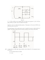
5-9.
Three physically identical synchronous
generators are operating in parallel. They are all
rated
for
a
full
load
of 3 MW
at
0.8
PF
lagging.
The
no-load
frequency of generator A is 61 Hz, and
its speed
droop
is 3.4
percent. The no-load frequency of generator B
is 61.5 Hz, and
its speed droop is
3
percent.
The no-load
frequency of generator C is 60.5
Hz, and
its speed droop is 2.6
percent.
(a)
If
a total load consisting of
7 MW
is
being supplied by this power system, what will
the
system
frequency be
and how will the power
be shared
among
the
three
generators?
(b)
Create a plot showing
the
power supplied by each generator as a
function
of
the
total
power
supplied to
all
loads
(you
may
use
MATLAB to create this plot).
At what load does one of the generators exceed
its ratings?
Which generator exceeds its ratings
first?
(c)
Is this
power sharing
in
(a)
acceptable? Why or why not?
(d)
What
actions could
an operator
take to
improve the real power
sharing among these generators?
S
OLUTION
(a)
Speed droop is
defined as
n
n
f
f
SD
nl
fl
100%
=
⋅
nl
fl
=
100%
⋅
fl
fl
n
f
so
f
=
f
nl
fl
SD
+
1
100
Thus,
the full-load frequencies of generators A, B, and
C are
f
fl,A
f
fl,B
f
nl,A
61 Hz
59.0 Hz
=
=
=
SD
A
3.4
1
1
+
+
100
100
f
nl,B
61.5 Hz
59.71 Hz
=
=
=
SD
B
3.0
1
1
+
+
f
fl,C
100
100
f
nl,C
60.5 Hz
58.97 Hz
=
=
=
SD
C
2.6
1
1
+
+
100
100
and the slopes
of
the power-frequency
curves are:
3 MW
1.5 MW
=
=
/Hz
S
PA
S
PB
S
PC
2
H
z
3
MW
1.676 MW
=
=
1.79 Hz
3 MW
1.961 MW
=
=
1.53 Hz
/Hz
/Hz
123
(a)
The total load
is 7 MW, so the system frequency is
(
)
=
(
)
+
(
)
+
LOAD
P
PA nl
s
A sys PB nl
f
f
s
B
f
sys
f
PC n
s
lC
f
sys
f
(
)
(
)
(
=
)
(
)
+
(
)
(
)
+
7 MW
1.5
61.0
sys
1.676
61.5
sys
1.961
60.5
f
f
sys
f
+
+
7
MW
91.5
1.
=
5.137
f
sys
=
306.2
f
sys
=
59.61 Hz
5
sys
103.07
1.676
sys
118.64
1.961
sys
f
f
f
The power supplied
by each generator
will
be
(
)
(
)
=
=
(
)
=
P
s
nl
A
P
A
A
f
sys
f
1.5 MW/Hz
61.0 Hz
59.61
Hz
2.09
MW
(
)
(
)
=
=
(
)
=
P
s
nlB
P BB
f
sys
f
1.676 MW/Hz
61.5 Hz
59.61 Hz
3.17
MW
(
)
(
)
=
=
(
)
=
P
s
nlC
P CC
f
sys
f
1.961 MW/Hz
60.5 Hz
59.61
Hz
1.74
MW
(b)
The
equation in part
(a)
can be re-written
slightly to express system frequency
as
a
function of load.
(
)
(
)
(
)
=
(
)
+
(
)
(
)
+
LOAD
1.5
61.0
sys
1.676
61.5
P
f
sys
1.961
60.5
f
sys
f
=
+
+
LOAD
91.5
1.5
sys
103.07
1.6
P
f
76
sys
118.64
1.96
f
=
5.137
sys
313.2
f
P
LOAD
1
sys
f
f
sys
=
313.2
L
P
OAD
5.137
A
MATLAB
program
that
uses this equation to determine the power sharing among the generators as a
function of load
is shown
below:
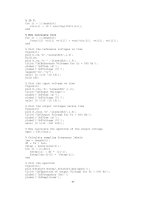
% M-file: prob5_9b.m
%
M-file to calculate and
plot the
power sharing
among
% three generators
as
a function of load.
% Define
values for this
generator
fnlA = 61.0;
% No-load freq of Gen
A
fnlB = 61.5;
% No-load freq of Gen
B
fnlC = 60.5;
% No-load freq of Gen
C
spA =
1.5;
% Slope of Gen A (MW/Hz)
spB =
1.676;
% Slope of Gen B (MW/Hz)
spC =
1.961;
% Slope of Gen C (MW/Hz)
Pload
= 0:0.05:10;
% Load in MW
% Calculate
the system frequency
fsys = (313.2 -
Pload) ./ 5.137;
% Calculate
the power
of
each generator
PA =
spA .* (
fnlA -
fsys);
PB =
spB .* (
fnlB -
fsys);
PC =
spC .* (
fnlC -
fsys);
% Plot the power sharing
versus load
plot(Pload,PA,'b-','LineWidth',2.0);
124
hold on;
plot(Pload,PB,'k ','LineWidth',2.0);
plot(Pload,PC,'r ','LineWidth',2.0);
plot([0 10],[3
3],'k','LineWidth',1.0);
plot([0 10],[0
0],'k:');
title
('\bfPower Sharing
Versus Total Load');
xlabel ('\bfTotal Load (MW)');
ylabel ('\bfGenerator
Power
(MW)');
legend('Generator A','Generator B','Generator C','Power
Limit');
grid on;
hold off;
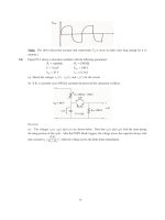
The
resulting plot is
shown below:
This plot reveals
that there
are power sharing problems both for high loads and
for
low loads.
Generator
B is
the
first
to exceed its ratings as load
increases. Its rated power is reached
at a total load of 6.45 MW. On
the other hand, Generator
C gets into trouble as the total
load
is
reduced.
When the total
load
drops to
2.4
MW, the direction of power flow reverses in
Generator C.
(c)
The power sharing in
(a)
is not acceptable, because
Generator 2 has
exceeded its power limits.
(d)
To improve the
power
sharing among the three generators in
(a)
without affecting the operating
frequency
of
the
system,
the
operator
should
decrease
the
governor
setpoints
on
Generator
B
while
simultaneously
increasing them in Generators
A and C.
5-10.
A paper mill has
installed three steam generators (boilers)
to
provide
process
steam
and also to use
some
its
waste
products as an
energy source. Since there is extra
capacity,
the mill has installed
three 5-MW
turbine
generators to
take
advantage of
the
situation.
Each generator is a 4160-V 6250-kVA 0.85-PF-
lagging two-pole
Y-connected
synchronous
generator with a
synchronous reactance of 0.75
&
and
an
armature resistance of 0.04
&
. Generators 1 and 2 have a characteristic power-frequency
slope
s
P
of 2.5
MW/Hz,
and generators 2 and
3
have
a
slope of 3 MW/Hz.
(a)
If the no-load frequency of each of the three generators is adjusted to 61 Hz, how
much
power will
the
three machines
be supplying when
actual system frequency
is 60
Hz?
125
(b)
What
is
the
maximum
power
the
three generators can supply in
this condition without the ratings of one
of them
being
exceeded? At what
frequency
does this limit occur?
How much
power
does
each
generator
supply at that
point?
(c)
What
would have to
be done to get all three generators to supply their rated real and reactive powers
at an
overall operating frequency
of
60 Hz?
(d)
What would
the
internal
generated
voltages of the
three generators be under this
condition?
S
OLUTION
(a)
If the system frequency is 60 Hz and the no-load
frequencies
of
the
generators
are
61
Hz,
then
the
power supplied by the generators will be
(
)
(
)
=
=
(
)
=
1 1P
P
s
nl1
f
sys
f
2.5 MW/Hz
61 Hz
60 Hz
2.5 MW
(
)
(
=
=
)(
)
=
2
P
2
P
s
nl2
f
sys
f
2.5 MW/Hz
61
Hz
60 Hz
2.5 MW
(
)
(
=
=
)(
)
=
3
P
3
P
s
nl3
f
sys
f
3.0 MW/Hz
61 Hz
60
Hz
3.0 MW
Therefore the total power supplied
by the generators is
8
MW.
(b)
The maximum
power supplied by any
one generator is (6250 kVA)(0.85)
=
5.31
MW.
Generator
3
will be
the
first
machine to reach that
limit. Generator 3
will supply this power at a frequency
of
(
)
(
)
=
5.31 MW
3.0
MW/Hz
61
Hz
f
sys
f
sys
=
.5 9
Hz23
At this
point the power supplied by
Generators 1 and 2 is
=
=
(
)
(
)
=
(
)
=
1 2
P
P
1P
s
nl1
f
sys
f
2.5 MW/Hz
61 Hz
59.23 Hz
4.425 MW
The total power
supplied by
the
generators
at this condition is 14.16 MW.
(c)
To get each of the generators to supply 5.31 MW at
60
Hz,
the
no-load
frequencies
of
Generator
1
and
Generator
2
would have to be adjusted to 62.12 Hz, and the no-load frequency of Generator 3 would
have
to
be
adjusted
to
61.77
Hz.
The field currents of the three generators must then be adjusted to get
them
supplying
a power
factor
of
0.85 lagging. At that point, each generator will be supplying its rated
real and reactive power.
(d)
Under
the
conditions
of
part
(c)
, which
are
the rated conditions
of the
generators, the
internal
generated
voltage would
be given by
=
+
+
A
A
E
V
⎞
A
I
S
A
R
jX
I
The phase
voltage of the
generators is 4160 V /
3
=
2402 V, and since the generators are Y-connected,
their rated current is
S
I
I
=
=
62
=
50 kVA
867
=
A
3
3
(
)
4160
V
A
L
T
V
The power factor is
0.85 lagging,
so
I
A
867
31.
=
8
A
°
.
Therefore,
=
+
+
A
A
E
V
⎞
A
I
S A
R
jX
I
2402
0
(
0.04
)(
)
867
31.8
A
(
0.
)(
)
75
867
31.8
A
E
A
=
°
+
&
°
j
+
&
°
126