Electric Machinery Fundamentals (Solutions Manual) Part 9 ppt
Bạn đang xem bản rút gọn của tài liệu. Xem và tải ngay bản đầy đủ của tài liệu tại đây (88.8 KB, 10 trang )
3
3
(
)
277 V
(
)
429 V
⎞
P
A
V
E
=
=
=
max
X
S
1.5
&
238 kW
(d)
Since
E
A
must
be
decreased linearly with frequency,
the maximum value
at 300 r/min
would be
15 Hz
(
)
429
V
129 V
=
=
E
A
,300
50 Hz
(e)
If the applied voltage
⎞
V
is derated by the same amount as
E
A
, then
V
⎞
= (15/50)(277) = 83.1 V.
Also, note
that
be
P
X
S
= (15/50)(1.5
&
) = 0.45
&
.
The
maximum
power that the motor could supply would
3
3
(
)
83.1 V
(
129
V
)
⎞
A
V
E
=
=
=
max
X
S
0.45
&
71.5 kW
(f)
As
we
can
see
by
comparing
the
results
of
(c)
and
(e)
,
the
power-handling
capability
of
the
synchronous motor varies
linearly
with
the
speed
of the motor.
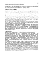
6-7.
A
208-V Y-connected
synchronous
motor
is drawing 40
A at unity power factor from a 208-V power
system.
The
field
current
flowing
under these
conditions is 2.7 A. Its synchronous reactance is 0.8
&
.
Assume a linear
open-circuit characteristic.
(a)
Find
the torque angle
™
.
(b)
How much field current would be required
to
make the motor operate at
0.8 PF
leading?
(c)
What
is the new torque
angle in part
(b)
?
S
OLUTION
(a)
The
phase
voltage
of
this
motor
is
V
⎞
=
120
V,
and
the
armature
current
is
Therefore, the internal generated voltage
is
I
A
40
0
A
=
°
.
=
E
V
I
I
A
A
⎞
A S A
R
jX
120
0
V
(
)
0.8
(
40
0
A
)
E
A
=
°
j
&
°
E
A
124
14.9
=
V
°
The torque angle
™
of
this machine is –14.9
°
.
(b)
A
phasor
diagram of the motor operating at a power factor of 0.78 leading is shown
below.
P
I
A
2
I
A
1
⎞
V
jX
I
S
A
}
P
EE
A
1
A
2
Since the power supplied
by
the
motor is
constant, the quantity
I
A
cos
⎝
,
which is directly proportional
to
power,
must
be constant. Therefore,
(
)
(
)(
)
I
A2
0.8
=
40 A
1.00
159
I
A2
50
36.
=
87
A
°
The internal generated
voltage required
to
produce this
current would be
=
E
V
I
I
2
2A
A
⎞
2A S A
R
jX
(
)(
)
E
A
2
120
0
V
=
°
j
0.8
50
&
36.8
7
A
°
E
A2
147.5
12.5
=
V
°
The internal generated voltage
E
A
is directly proportional to the field flux,
and we have assumed in this
problem that the flux is
directly
proportional
to
the field current. Therefore, the required
field current
is
E
A
2
147
V
(
)
2
=
=
.7 A
3.20 A
=
2
1
F
F
I
I
E
1
A
124 V
(c)
The new torque
angle
™
of this
machine is –12.5
°
.
6-8.
A synchronous machine
has a synchronous
reactance of 2.0
&
per phase and an armature resistance of 0.4
&
per phase. If
E
A
=460
-8
°
V and
⎞
V
= 480
0
°
V, is this machine a motor
or
a
generator?
How
much power
P
is
this
machine
consuming
from
or
supplying
to the electrical system? How much reactive
power
Q
is this machine
consuming from or supplying to the electrical
system?
S
OLUTION
This machine is a motor,
consuming
power
from
the power system, because
E
A
is lagging
⎞
V
.
It is also
consuming
reactive power, because
A
cos
E
V
™
<
⎞
. The current flowing in this
machine is
⎞
A
V
E
I
480
0
V
°
4
60
8
V
°
33.6
9.6
A
=
=
=
°
A
0.4
2.0
+
+
&
A S
R
jX
j
Therefore the real
power consumed
by this
motor is
3
cos
3
(
)
480 V
(
3
=
=
3.6 A
)
cos
(
9.6
)
47.7 kW
°
=
⎞
A
P
V
I
⎝
and the reactive power consumed by
this motor
is
3
sin
3
(
)
480 V
(
3
=
=
3.6 A
)
sin
(
9.6
)
8.07
kVA
°
R
=
⎞
⎝
A
Q
V
I
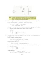
6-9.
Figure P6-2 shows a synchronous motor phasor diagram for a motor operating at a leading power factor
with no
R
A
. For this motor, the torque angle is given by
tan
=
™
X
I
co
S A
s
⎝
V
X
⎞
+
si
S A
I
n
⎝
™
=tan
-1
X
I
co
S
A
s
⎝
V
X
⎞
+
si
S
A
I
n
⎝
Derive an
equation
for the torque
angle of the synchronous
motor
if the
armature
resistance is included
.
160
S
OLUTION
The phasor diagram with the armature resistance considered
is shown
below.
I
A
X
I
⎞
V
S
A
⎝
™
sin
⎝
}
cos
⎝
I
X
jX
I
S
A
S
A
⎝
⎝
R
I
A
A
E
A
cos
⎝
R
I
Therefore,
™
A
A
⎝
⎝
tan
=
X
I
co
S A
s
+
A
R
I
si
A
n
⎝
⎝
+
V
X
⎞
si
S A
n
I
A
c
A
R
o
I
s
™
⎝
⎝
=
tan
1
X
I
co
S
A
s
+
A
R
I
sin
A
⎝
⎝
+
V
X
⎞
sin
S
A
I
A
R
c
A
o
I
s
6-10.
A 480-V 375-kVA 0.8-PF-lagging Y-connected synchronous generator has a
synchronous
reactance
of
0.4
&
and a
negligible armature resistance.
This
generator
is supplying power to a 480-V 80-kW 0.8-PF-
leading
Y-connected synchronous motor with a synchronous reactance of 1.1
&
and a negligible armature
resistance.
The synchronous generator is adjusted to have a terminal voltage of 480 V when the motor is
drawing the rated power
at unity
power factor.
(a)
Calculate the magnitudes and
angles of
E
A
for
both machines.
(b)
If the
flux of the motor is increased by 10 percent, what happens to the terminal voltage of the power
system? What
is its new
value?
(c)
What
is the power factor
of
the motor
after the increase in
motor flux?
S
OLUTION
(a)
The motor is operating at rated power
and unity
power factor, so the current flowing in the motor is
P
I
I
=
=
=
80 kW
96.2 A
=
,m ,mA L
(
)
3
PF
3
(
)
480 V
1.0
T
V
so
I
A,m
96.2
0
A
=
°
.
This machine
is Y-connected, so the phase
voltage
is
V
⎞
= 480 /
3
=
277 V.
The
internal
generated
voltage of the motor is
161
=
E
V
I
,m
⎞
,m
jX
,mA S A
(
)(
)
E
,m
A
E
,mA
277
0
V
=
°
j
1.1
297
20.
=
9
V
°
96
&
.2
0
A
°
This same current comes from the generator, so the internal generated voltage
of
the generator is
=
+
E
V
I
,g
⎞
,g
jX
,g
A
S
A
(
)(
)
E
,gA
277
0
V
=
°
j
0.4
+
96
&
.2
0
A
°
E
A
,g
280
7.9
V
=
°
j
0.4
&
I
A,g
I
A,m
j
1.1
&
+
+
+
E
A,g
-
V
⎞
,g
V
⎞
,m
+
E
A,m
-
-
-
E
A,g
A
jX
I
I
A
I
V
⎞
S,g A
⎞
V
jX
I
S,m A
E
A,m
Generator
Motor
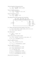
(b)
The power supplied by the generator to the motor will be
constant
as the field
current of the motor
is
varied.
The
10%
increase
in
flux
will
raise
the internal generated voltage of the motor to (1.1)(297 V) =
327 V.
To make finding the new conditions easier,
we
will
make the
angle of the phasor
E
,
A
g
the reference during
the following calculations
.
The resulting phasor
diagram is
shown below.
E
I
A,g
A
g
™
jX
I
m
™
S,g
A
⎞
V
jX
I
Then by Kirchhoff’s
Voltage
Law,
E
A,m
S,m
A
=
+
E
E
, ,A g
A m
+
I
j
X
X
,S g ,
(
)
S m A
162
or
A
I
=
, ,A g A m
E
E
+
j
X
X
, ,
(
)
S g S m
Note that this combined phasor diagram looks
just
like
the diagram of a
synchronous
motor,
so
we
can
apply the power
equation
for
synchronous motors to this
system.
, ,A g A m
E
E
P
=
3
sin
©
+
, ,S g S m
X
X
™
™
=
+
.
From this equation,
where
©
g m
(
)
X
X
+
P
(
)
&
(
)
,
,
1
1
S
g
S
m
sin
1.5
80
kW
25.9
sin
©
(
)(
=
=
)
=
°
Therefore,
3
,
,
A
g
A
m
E
E
E
E
3
280V
327 V
°
°
,
,
A
g
A
m
280
0
V
327
=
=
25.9
V
95.7
5.7
A
=
°
A
I
+
&
,
,
(
)
S
g
j
X
S
X
m
1.
j
5
The phase voltage of the system would be
=
V
E
I
=
°
(
)(
&
)
°
=
°
⎞
,
,
A
g
jX
S
g
A
280
0
V
j
0.4
95.7
5.7
A
286
7.6
V
If we make
⎞
V
the reference (as we usually
do),
these voltages
and currents
become:
E
,
A
g
280
7.6
V
=
°
V
⎞
286
0
V
=
°
E
,
A
m
327
18.
=
3
V
°
I
A
95.7
13.3
=
A
°
The new
terminal voltage is
(
)
3
286 V
495
V
T
V
=
=
, so the system
voltage has
increased
.
(c)
The power factor of the motor is
now
-18.3
°
implies
an impedance angle
of
18.3
°
.
Note:
The reactive
power in
the
motor is now
(
)(
=
=
PF
cos
(
)
13.3
=
0.9
°
73
=
leading
,
since a current angle of
)
(
)
°
=
motor
3
⎞
A
sin
Q
V
I
⎝
3
286 V
95.7 A
sin
13.3
18.9 kVAR
The motor is now supplying 18.9
kVAR to the
system. Note that
an increase in machine flux
has
increased
the
reactive
power
supplied by the
motor and also
raised the
terminal voltage of the system
.
This is
consistent with
what
we learned about reactive power sharing in Chapter 5.
6-11.
A
480-V,
100-kW,
50-Hz,
four-pole, Y-connected synchronous motor has a rated power factor of 0.85
leading.
At
full load, the efficiency is 91 percent.
The
armature resistance
is
0.08
&
, and the synchronous
reactance is
1.0
&
.
Find the following quantities for this machine
when it is
operating
at full load:
(a)
Output
torque
(b)
Input
power
(c)
m
n
(d)
E
A
163