Flash CS3 For Dummies PHẦN 3 potx
Bạn đang xem bản rút gọn của tài liệu. Xem và tải ngay bản đầy đủ của tài liệu tại đây (1.08 MB, 40 trang )
ߜ Close Path: Select this check box to include a fill as well as an outline
around the entire shape. (The Close Path check box is selected by
default.) Deselect the Close Path check box to omit the fill and draw an
outline only. If you used the Start Angle and End Angle controls to create
part of an oval or a circle, you get an unclosed shape when you deselect
the Close Path check box, as shown in Figure 3-10.
When you deselect the Close Path check box to create an open oval, you
draw only the outline. What happens if you defined the oval without a fill?
The entire object disappears! To get it back, choose Edit➪Undo and add an
outline. For detailed instructions, see the discussion of the Rectangle tool
earlier in this chapter.
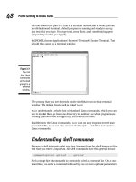
Figure 3-10 shows oval primitives with the following parameters from left to
right: an inner radius; no inner radius, but start and end angles; a closed path
with an inner radius and start and end angles; and finally, an open path with
an inner radius and start and end angles. You can see that opening the path
removes the fill.
When you select an Oval Primitive, you see two markers, one at the inner
radius (or center, if the inner radius is 0) and one at the outer radius. You can
drag the inner radius to change it.
Creating Curves with the Pen
The Pen tool lets you draw Bezier curves, also called splines. Bezier curves
are named after the French mathematician Pierre Bézier, who first described
them. By using the Pen tool, you can create smooth curves that flow into
each other. You can also create straight lines.
Figure 3-10:
I had a
donut. A
little crea-
ture came
and ate a
bite. Then it
went on to
eat the rest,
leaving only
the outline!
60
Part II: 1,000 Pictures and 1,000 Words
08_121009 ch03.qxp 4/10/07 6:17 PM Page 60
You can set preferences for the Pen tool by choosing Edit➪Preferences
(Windows) or Flash➪Preferences (Mac) and clicking the Drawing category.
We suggest enabling the Show Pen Preview option to display a preview of the
line or curve while you draw. This setting helps you get a better idea of what
the result will be. Click OK when you finish setting your preferences.
To create a line or curve, choose the Pen tool in the Tools panel. What you do
next depends on whether you want to draw a straight line or a curve. The fol-
lowing sections show you how to draw both.
Drawing straight lines
To draw a straight line with the Pen tool, follow these steps:
1. To create a line segment, click the start point and then click the
end point.
2. Continue to add line segments by clicking additional points.
3. Double-click to complete the process.
You can also Ctrl+click (Windows) or Ô+click (Mac) anywhere off the
line. Flash previews segments in a color that depends on the layer you’re
working on — see the color of the square next to the current layer as
shown on the Timeline. (Chapter 6 explains layers in full.) When you
choose another tool, Flash displays Beziers in the current stroke color.
Close a figure by pointing near the start point. You see a small circle. Click
the start point, and Flash closes the figure.
Drawing curves
Drawing curves with the Pen tool involves a couple of steps, depending on
the complexity of the curve that you want to create. The main principle to
understand is that you define the curve by specifying the location of anchor
points. Each anchor point controls a bend in the curve. To draw a curve with
the Pen tool, follow these steps:
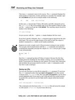
1. Click where you want to start and drag the mouse in the desired
direction. About one-half of the way to the next anchor point (the end
of the curve), release the mouse button, as shown in Figure 3-11(a).
You see tangent lines that define both the direction and length of each
part of the curve, as shown in Figure 3-11(b).
61
Chapter 3: Getting Graphic
08_121009 ch03.qxp 4/10/07 6:17 PM Page 61
2. To create one curve, move the mouse cursor to the desired end of the
curve; then double-click to end the curve, as shown in Figure 3-11(c).
If you set preferences to show a preview of the curve (as we explain
earlier in the section “Creating Curves with the Pen”), you also see a
stretchy line attached to your mouse cursor that previews the shape.
3. To continue to draw curves, again click and drag in the desired direc-
tion, release the mouse button, and move the mouse cursor to wherever
you want the end of the next curve to be. Double-click to end the curve.
If you drag in an opposing direction to the first curve, you create a simple
curve, sometimes called a C curve. If you drag in a similar direction to the first
curve, the curve doubles back on itself, which is sometimes called an S curve.
For both lines and curves, you can press and hold Shift to constrain the lines
or curves (the tangent lines) to 45-degree angles.
Drawing curves with the Pen tool takes practice, but you’ll soon get the
hang of it.
Getting Artistic with the Brush
The Brush tool lets you create artistic effects that look like painting. You can
adjust the size and shape of the brush, and if you have a pressure-sensitive
pen and tablet, you can adjust the width of the stroke by changing the pres-
sure on the pen.
To paint with the Brush tool, select it on the Tools panel and then click and
drag anywhere on the Stage. Press and hold Shift while you brush to keep
your strokes either horizontal or vertical. The brush doesn’t have a stroke
(line) color. The brush creates only fills. Use the Fill Color drop-down list in
the Property inspector or in the Colors section of the Tools panel to select a
fill color.
(a) (b) (c)
Figure 3-11:
Drawing a
curve with
the Pen tool:
1, 2, 3, and
you have a
big nose!
62
Part II: 1,000 Pictures and 1,000 Words
08_121009 ch03.qxp 4/10/07 6:17 PM Page 62
When you choose the Brush tool, the Brush modifiers appear in the Options
section of the Tools panel, as shown in Figure 3-12.
Brush mode modifier
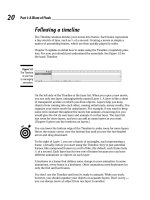
The Brush mode modifier determines how the brush relates to existing
objects on the Stage. Here are your choices for Brush mode. (Figure 3-13
shows some examples.)
ߜ Paint Normal: You just paint away, oblivious to anything else. Use this
setting when you don’t need to worry about other objects.
ߜ Paint Fills: You paint fills and empty areas of the Stage. The paint doesn’t
cover lines. Note that your lines seem to be covered while you paint, but
they reappear when you release the mouse button.
ߜ Paint Behind: You paint behind existing objects, but only in blank areas
of the Stage. While you paint, the brush seems to cover everything, but
your existing objects reappear when you release the mouse button. You
can messily paint over your objects, knowing that they won’t be affected.
ߜ Paint Selection: You paint only a filled-in area that you previously
selected. While you paint, your existing objects are covered, but they
reappear when you release the mouse button. You don’t need to worry
about painting within the lines because Flash fills only the selected area.
ߜ Paint Inside: You paint inside lines. Only the fill where you start brushing
is painted. Paint Inside also paints an empty area on the Stage if that’s
where you start brushing. Again, at first the paint seems to cover up every-
thing, but when you release the mouse button, Flash keeps your paint nice
and neat, inside the lines — like every little kid discovers in kindergarten.
Lock Fill
Brush Shape
Use Tilt
Brush Mode
Brush Size
Use Pressure
Figure 3-12:
The Brush
modifiers
control the
size and
shape of the
brush as
well as how
the brush
relates to
existing
images.
63
Chapter 3: Getting Graphic
08_121009 ch03.qxp 4/10/07 6:17 PM Page 63
Brush Size drop-down list
Click the Brush Size drop-down list and select a size in the list of circles. This
list defines the width of the brush. If you use a Brush mode that helps you
draw neatly, such as Paint Selection, you don’t need to be too concerned with
the size of the brush. On the other hand, if you’re creating an artistic effect
by using Paint Normal mode, the width of the brush is important.
Brush Shape drop-down list
Flash offers several brush shapes you can choose from. Click the Brush
Shape drop-down list and select one of the shapes. Each shape produces a
different effect, especially when you paint at an angle — you just need to try
Original corn Corn with worms
— Paint Normal
Corn with bad kernels
— Paint Fills
Corn with background
— Paint Behind
Sheath with gray gradient
— Paint Selection
Corn with bad kernels
— Paint Inside
Figure 3-13:
Set the
Brush mode
when using
the Brush
tool to get
the effect
you want.
64
Part II: 1,000 Pictures and 1,000 Words
08_121009 ch03.qxp 4/10/07 6:17 PM Page 64
them out to see what works best. Figure 3-14 shows a honey jar drawn with
various brush shapes.
Pressure and Tilt modifiers
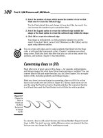
If you have a pressure-sensitive pen and tablet, Flash also displays a Pressure
modifier so that you can vary the width of your strokes according to the pres-
sure you put on your pen while you draw. Click the Use Pressure tool (refer to
Figure 3-12) to turn on this feature.
Flash fully supports pressure-sensitive pens and adds the ability to use the
opposite end of the pen to erase — just like a real pencil. Figure 3-15 shows
this type of pen and tablet.
A pressure-sensitive pen works together with a tablet to help you draw in
Flash. The tablet tracks the movement and pressure of the pen while you
draw. You can also use the pen as a mouse to choose menu and dialog box
items. In other words, if you want, you can use the pen for all your Flash
work. Alternatively, you can use the pen and tablet just for drawing and use
the mouse when you want to work with menus and dialog boxes.
The Tilt modifier varies the angle of your brush stroke when you vary the
angle of the stylus on the tablet. For example, holding the stylus straight up
and down produces a different shape of brush stroke than the one you get if
you hold the stylus at a 45-degree angle to the tablet.
Use the Tilt modifier for fine control over your brush strokes. Click the Use
Tilt tool in the Options section of the Tools panel to turn on this feature. You
see the effect most clearly with a large brush size and one of the narrow
brush shapes. When you start to draw, change the angle of the stylus to the
tablet. Watch the cursor shape turn, giving you a hint as to the shape of the
brush stroke. Try brushing at a few angles to see how this works.
Figure 3-14:
Each brush
shape
creates a
different
effect —
especially at
the ends of
the stroke.
65
Chapter 3: Getting Graphic
08_121009 ch03.qxp 4/10/07 6:17 PM Page 65
Photo courtesy of Douglas Little of Wacom
See the “A Rainbow of Colors” section, later in this chapter, for an explana-
tion of the Lock Fill modifier, one of the brush tool’s modifiers.
Brush smoothing
Smoothing brush strokes is similar to smoothing pencil strokes. You can
finely adjust how much your brush strokes are smoothed after you finish
drawing them. You can set smoothing anywhere from 0 to 100.
To set brush smoothing, follow these steps:
1. Click the Brush tool.
2. Open the Property inspector if it’s not open (choose Window➪
Properties➪Properties). Or if the inspector is open, expand it to its
full size if necessary.
3. Use the Smoothing text box or slider to set a new value.
The lower values change your strokes less. Therefore, if you set Smoothing
to 0, the brush stroke is closest to what you actually drew. Lower values
create more vectors, resulting in a larger file size for your movie. The
higher values smooth and simplify your strokes more.
Figure 3-15:
This Wacom
pen and
tablet set is
easier to
draw with
than a
mouse and
enables you
to easily
vary the
brush width
as you
draw.
66
Part II: 1,000 Pictures and 1,000 Words
08_121009 ch03.qxp 4/10/07 6:17 PM Page 66
Pouring on the Paint
The Paint Bucket creates fills that fill shapes with color. You might want to fill
an enclosed area that you created with the Line or Pencil tool. You can also
fill enclosed shapes created with the Pen or Brush tool, as we explain earlier
in this chapter.
The Paint Bucket is also handy for changing existing fills. You can change the
color as well as fiddle around with gradient and bitmap fills. (See Chapter 4
for more on editing fills.)
To use the Paint Bucket, choose it in the Tools panel. Set the color by clicking
the Fill Color tool and selecting a color. Alternatively, you can use the Fill
Color drop-down list in the Property inspector.
Flash can fill areas that aren’t completely closed. The Gap Size modifier (in
the Options section of the Tools panel) determines how large of a gap Flash
will overlook to fill in an almost enclosed area. Choices range from Don’t
Close Gaps to Close Large Gaps. Because small and large are relative terms,
you might have to experiment to get the result you want. After you choose an
option from the Gap Size modifier, click any enclosed or almost enclosed area
to fill it, as shown in Figure 3-16.
After you use the Paint Bucket to fill a shape created with another tool, you
can delete the outline of the shape and keep just the fill.
Strokes, Ink
You use the Ink Bottle tool to create an outline on an existing shape. You can
use the Ink Bottle tool also to change an existing line, or stroke.
Figure 3-16:
Fill areas
that aren’t
completely
closed by
using the
Gap Size
modifier.
67
Chapter 3: Getting Graphic
08_121009 ch03.qxp 4/10/07 6:17 PM Page 67
To use the Ink Bottle tool, click it on the Tools panel. Click the Stroke Color
tool to select a color. Use the Property inspector, as we explain earlier in this
chapter (in the discussion of the Pencil tool) to select a line thickness and
line style. Then click anywhere on the shape. If the shape has no existing line,
Flash adds the line. If the shape has a line, Flash changes its color, width, or
style to the settings you specified in the Property inspector.
A Rainbow of Colors
Flash offers you lots of color options. By default, Flash uses a palette of 216
colors that are Web safe, which means they look good on all Web browsers
and monitors. Or, in these days when most computers can displays millions
of colors, you can create your own colors.
Solid citizens
When you choose either the Stroke Color or Fill Color tool, Flash opens the
current color palette, which is the active set of colors that Flash uses.
Creating new colors or editing existing colors
Flash provides two ways for you to specify your own colors:
ߜ Choose the Stroke Color or Fill Color tool in the Tools panel and click
the Colors Window button in the upper-right corner of the palette to
open the Color dialog box.
ߜ Choose Window➪Color to open the Color panel.
These two methods duplicate each other; here, we explain how to use the
Color panel, which is shown in Figure 3-17.
Swap Colors
Options menu
Fill style
Color space
Brightness
Hex value
Current/
previous
color
Stroke Color
Fill Color
Black and White
No Color
Color specifications
Transparency value
Figure 3-17:
Use the
Color panel
to create
your own
colors.
68
Part II: 1,000 Pictures and 1,000 Words
08_121009 ch03.qxp 4/10/07 6:17 PM Page 68
If you select an object before you use the Color panel, the object’s color
changes immediately when you change the color in the panel.
To create a new color or edit an existing color, follow these steps:
1. Click the Options menu icon in the upper-right corner of the Color
panel to open the pop-up menu, and then choose the color mode.
RGB specifies a color according to red, green, and blue components; HSB
specifies a color by hue, saturation, and brightness. You can also define
a color by using hexadecimal notation, which is the color system used on
the Web: Just type the hexadecimal code in the Hex box of the Color panel.
2. Click the Stroke Color or Fill Color icon to specify which color you
want to change — stroke or fill.
Click the icon to the left of the Stroke Color or Fill Color box — not the
box itself. (If you click the box, you open the color palette.)
3. Type the color specs in the text boxes, use the sliders (click the down
arrow) to drag to the desired color, or find a color in the color space
that’s close to the one that you want. Then click that color.
4. Set the level of opacity/transparency (also called alpha) by using the
Alpha slider or by typing a number in the Alpha box.
A setting of 0% is completely transparent and 100% is opaque.
5. If you want to create a new color swatch, click the Options menu icon
and choose Add Swatch.
Flash adds the new color to the color palette so that you can access it
from the Stroke Color or Fill Color boxes on the Tools panel, the
Property inspector, and the Swatches panel.
Managing colors
If you’ve added or changed colors, you can save this new palette. (A palette is
a set of colors.) You can then save the palette for use in other Flash movies
or import a color palette from another Flash movie (so that you don’t have to
bother creating the colors again). Color palettes are saved as .clr files and
are called Flash color set files. To save a color palette, choose Save Colors in
the Swatches option menu. (Choose Window➪Swatches to open the Swatches
panel and click the Options menu icon in the upper-right corner of the panel
to display the menu.) In the Export Swatch dialog box, choose a location for
the file, name it, and click Save.
Adobe Fireworks and Photoshop use Color Table files (.act files), and Flash
can save and import these as well. To save your color palette as an .act file,
choose Color Table (*.act) in the Save as Type drop-down list in the Export
Swatch dialog box.
69
Chapter 3: Getting Graphic
08_121009 ch03.qxp 4/10/07 6:17 PM Page 69
To import a color palette that you’ve saved, use the Options menu of the
Swatches panel. Choose Add Colors if you want to append this imported palette
to an existing palette. Choose Replace Colors if you want the imported palette
to replace an existing palette. You can use the same Swatches panel Options
menu to manage your color palettes. Choose from the following options:
ߜ Duplicate Swatch: Creates a duplicate of a swatch. Do this when you
want to create your own color and use an existing color as a basis.
ߜ Delete Swatch: Deletes a color.
ߜ Load Default Colors: Replaces the active color palette with the Flash
default palette.
ߜ Save as Default: Saves the active color palette as the default palette for
any new Flash movies that you create.
ߜ Clear Colors: Clears all colors except black and white — for when you
really want to start from scratch.
ߜ Web 216: Loads the Web-safe, 216-color palette.
ߜ Sort by Color: Sorts the display of colors by luminosity.
Gradient colors
So you’re bored with solid colors and want something more interesting.
Gradients are combinations of two or more colors that gradually blend from
one to another. Flash can create gradients of as many as 16 colors — quite a
feat. Gradients are always used as fills. The gradient can be linear or radial
(concentric), as shown in Figure 3-18. Because the figure isn’t in color, it can’t
begin to show you the glory of gradients.
Linear gradient Radial gradient
Figure 3-18:
Linear and
radial
gradients
make your
graphics
more
interesting
than plain
solid colors.
70
Part II: 1,000 Pictures and 1,000 Words
08_121009 ch03.qxp 4/10/07 6:17 PM Page 70
Flash offers a few standard gradients that you can find at the bottom of the
color palette. But you often need a more customized look, and Flash has the
tools to create just about any gradient you want.
Radial gradients look best on curved objects. A circle can suddenly look like
a sphere when you fill it with a radial gradient. If you put white at the center
of a radial gradient, it gives the impression of light highlights. Linear gradi-
ents look best on straight objects.
To create your own gradient, follow these steps:
1. Choose Window➪Color to open the Color panel (refer to Figure 3-17).
Then choose Linear or Radial in the Fill Style drop-down list.
You see a gradient bar with color pointers that specify the colors of the
gradient and where the gradient changes from one color to the next.
If you select a fill before you use the Color panel, the object’s fill color
changes immediately when you change the gradient in the Color panel.
2. To use an existing gradient as a starting point, click the Fill Color box
on the Tools panel and choose a gradient from the bottom of the color
palette.
You can also choose Window➪Swatches to open the Swatches panel and
choose a gradient from the bottom of the color palette there.
3. To specify the color for each color pointer, click and hold the pointer
and then release the mouse button (this is like a long mouse click).
When the color swatches appear, select a color.
You can click the Fill Color box and select an existing color from the
color palette or specify a new color by using the methods we describe in
the earlier section, “Creating new colors or editing existing colors.”
Note that when you click a pointer, its point turns black to indicate that
it’s the active pointer. The square beneath the point displays the color
pointer’s current color.
4. To change the number of colors in the gradient, add or delete color
pointers.
To add a color pointer, click where you want the pointer to appear,
just below the gradient bar. To delete a color pointer, drag it off the gra-
dient bar.
5. To adjust where the color changes, drag a color pointer to the left or
right.
71
Chapter 3: Getting Graphic
08_121009 ch03.qxp 4/10/07 6:17 PM Page 71
6. To add control over how colors are applied to a selected shape
beyond the gradient, select one of the following overflow modes in
the Overflow drop-down list:
ߜ Extend: Extends the last or outermost gradient color past the end
of the gradient
ߜ Reflect: Fills the shape by mirroring the gradient pattern
ߜ Repeat: Repeats the gradient from beginning to end
To use these effects, fill a shape with a gradient and then use the
Gradient Transform tool to reduce the size of the gradient so that it no
longer completely fills the shape. (We discuss the Gradient Transform
tool in Chapter 4.) Then try out the three overflow modes to see the
results.
Select the Linear RGB check box to create a gradient that complies with
Scalable Vector Graphics (SVG) standards. SVG is an XML language for
describing 2-D graphics.
7. To save the gradient, click the menu icon in the upper-right corner of
the Color panel and choose Add Swatch.
The new gradient now appears in the color palette of the Fill Color box on the
Tools panel and in the Swatches panel. Go ahead and fill something with it!
You can also move a gradient’s center and focal points, change its width and
height, rotate it, scale it, skew it, and tile it. See Chapter 4 for more on editing
gradients.
Bitmap fills
You can create the coolest, weirdest fills by importing a bitmap graphic and
using the bitmap to fill any shape. For a hypothetical Web site protesting
genetically engineered foods, for example, we could find a bitmap of a bug
(representing the Bt bacteria genetically engineered into corn) and use it to
fill a graphic of corn. Figure 3-19 shows the result.
To use a bitmap graphic to fill a shape, follow these steps:
1. Create the object or shape that you want to fill.
2. Select the object.
3. If you haven’t already imported the bitmap, choose File➪Import➪
Import to Library, choose the bitmap you want, and then click
Open/Import.
72
Part II: 1,000 Pictures and 1,000 Words
08_121009 ch03.qxp 4/10/07 6:17 PM Page 72
We explain more about importing graphics in the section “The Import
Business — Using Outside Graphics,” at the end of this chapter.
4. In the Color palette, chose Bitmap from the Type drop-down list and
choose your bitmap from the swatches.
Flash applies the bitmap as a fill for the selected object. You may need
to scale the bitmap. See the section on transforming fills in Chapter 4 for
details.
For either method of choosing a bitmap, you can choose the Brush tool
(instead of using the Paint Bucket tool) and then brush with the bitmap. Use
a brush size that’s thick enough to clearly show the bitmap.
Locking a fill
Flash has another trick up its sleeve for gradient or bitmap fills. A locked fill
looks as though the fill is behind your objects and the objects are just uncov-
ering the fill. As a result, if you use the same fill for several objects, Flash
locks the position of the fill across the entire drawing surface instead of fixing
the fill individually for each object. Figure 3-20 shows an example of a locked
fill. In this figure, you see some windows and portholes filled with a locked
bitmap of the sky. Doesn’t it look as though the sky is really outside the
windows?
Figure 3-19:
You can fill
any shape
with a
bitmap,
repeated
over and
over and
over.
73
Chapter 3: Getting Graphic
08_121009 ch03.qxp 4/10/07 6:17 PM Page 73
To lock a fill, choose the Brush tool or the Paint Bucket tool with a gradient
or bitmap fill, as we explain in the two preceding sections. Then click the
Lock Fill modifier in the Options section of the Tools panel. Start painting
where you want to place the center of the fill and continue to other areas.
Drawing Precisely
If drawing in Flash seems too loosey-goosey to you, you need to know about a
few features that can help you draw more precisely. Other programs do offer
more precise tools, but Flash might have the tools you need.
The ruler rules
To help you get your bearings, you can choose View➪Rulers to display the
Flash ruler along the top and left side of the Stage, as shown in Figure 3-21.
To give yourself more room to work while you create drawing objects on the
Stage, you can hide the Timeline by choosing Window➪Timeline. Do the
same to display the Timeline again when you need to work with layers or
start animating your work.
By default, the ruler is measured in pixels. Computer screens are measured
by how many pixels they display horizontally and vertically. Pixels are useful
for Web site work because Web browsers work with only this unit. A pixel,
however, is not a fixed physical size because it depends on the resolution
capacity and settings of your screen. You might find it easier to think in
inches or millimeters.
Figure 3-20:
When you
lock a fill,
the fill’s
pattern
continues
across the
Stage but
appears
only where
you use it.
74
Part II: 1,000 Pictures and 1,000 Words
08_121009 ch03.qxp 4/10/07 6:17 PM Page 74
You can set the ruler to the unit of measurement that is most helpful to you.
Choose Modify➪Document to open the Document Properties dialog box. In
the Ruler Units drop-down list, choose one of the units (pixels, inches, points,
centimeters, or millimeters) and then click OK.
When the ruler is displayed, lines appear on the top and side rulers when-
ever you drag an object — either while creating it or editing it. For example,
when you drag to create a rectangle, you see a line on each ruler telling you
where you started and where you ended up. If you’re moving the rectangle,
Flash displays two lines on each ruler indicating the outside dimensions of
the rectangle. You can easily move the rectangle 1 inch — or 50 pixels — to
the left by looking at the lines on the top ruler.
Using guides
Guides help you lay out the Stage more precisely. Guides (refer to Figure 3-21)
are horizontal and vertical lines that you can use as drawing aids while you
work. Don’t worry — guides never appear in the published Flash Player file.
To use the guides, you must display the rulers, as we describe in the preced-
ing section. To display guides, choose View➪Guides➪Show Guides. But that
action simply turns on the Guides feature; you still don’t see anything!
To display the guides, you need to drag them from the rulers. Drag from the
left ruler to create a vertical guide, and drag from the top ruler to create a
horizontal guide.
To customize the guides, choose View➪Guides➪Edit Guides to open the
Guides dialog box, where you can choose the guide color or clear all the
Figure 3-21:
Display the
ruler to help
you draw
more
precisely;
for more
control,
drag guides
onto the
Stage.
75
Chapter 3: Getting Graphic
08_121009 ch03.qxp 4/10/07 6:17 PM Page 75
guides. To force objects to snap (attach) to the guides, select the Snap to
Guides check box in the Guides dialog box. You can use the Snap Accuracy
drop-down list in the Guides dialog box to choose how precisely Flash snaps
to the guides. To lock the guides so that they don’t move while you work,
choose View➪Guides➪Lock Guides. To remove an individual guide, drag it
back to its vertical or horizontal ruler.
Working with the grid
You can display a grid on the Stage to help you draw more accurately and
gauge distances. The grid exists only to guide you — it never appears when
the movie is printed or published on a Web site. Simply displaying the grid
doesn’t constrain your objects to points on the grid. Use the grid by itself
when you want a visual guide for drawing, sizing, moving, and laying out
the Stage.
To display the grid, choose View➪Grid➪Show Grid. Use the same command
to hide the grid again. You can set the size of the grid squares and change the
color of the grid lines in the Grid dialog box. To open the dialog box, choose
View➪Grid➪Edit Grid.
You can change the units of measurement used for the grid by choosing
Modify➪Document. In the Modify Document dialog box, select the unit that
you want in the Ruler Units drop-down list and click OK.
Snapping turtle
When you want even more precision, you can turn on snapping. Snapping
tells Flash to snap objects to the intersections on the grid or to other objects.
Usually, you want the grid on when you use snapping so that you can see the
snap points.
To turn on snapping, choose the Selection tool and click the Snap modifier in
the Options section of the Tools panel or Choose View➪Snapping➪Snap to
Objects. To snap to the grid, choose View➪Snapping➪Snap to Grid. Use the
same method to turn snapping off again.
Snapping pulls your cursor to the grid points and to existing objects while
you work. You can take advantage of snapping both while drawing new objects
and editing existing objects. When you have snapping on and select an object,
Flash displays a small, black circle and snaps the circle to the grid points.
76
Part II: 1,000 Pictures and 1,000 Words
08_121009 ch03.qxp 4/10/07 6:17 PM Page 76
Setting snap-to-grid preferences
You can get downright picky about how Flash snaps to grid points. Do you
want the end of a line (for example) to always snap, or should it snap only
if it’s close to a grid point or an existing object? To set your preferences,
choose View➪Grid➪Edit Grid. In the Snap Accuracy drop-down list, select
one of the options, which range from Must Be Close to Always Snap.
Setting snap-to-objects preferences
Because snapping applies to objects as well as grid points, you can sepa-
rately set how Flash snaps to objects. Choose Edit➪Preferences (Windows)
or Flash➪Preferences (Mac) and then click the Drawing category. In the
Connect Lines drop-down list, select Must Be Close, Normal, or Can Be
Distant. Although Flash calls this the Connect Lines setting, it affects rectan-
gles and ovals as well as the lines you draw with the Line and Pencil tools.
This setting also affects how Flash recognizes horizontal and vertical lines
and makes them perfectly horizontal or vertical. For example, the Can Be
Distant setting adjusts a more angled line than the Must Be Close setting.
Pixel, pixel on the wall
If the grid isn’t precise enough, you can snap to pixels. Choose View➪
Snapping➪Snap to Pixels to toggle snapping to pixels on and off. If Snap to
Pixels is on, Flash automatically displays the pixel grid when you zoom in to
400 percent or higher. With Snap to Pixels on, you can snap all objects that
you create or move to the pixel grid.
When Snap to Pixels is on, you can press the C key to temporarily turn off
pixel snapping. In the same situation, you can hold down the X key to tem-
porarily hide the pixel grid (but not while you’re in the process of drawing).
You can also precisely align existing objects. For more information, see
Chapter 4.
The Import Business — Using
Outside Graphics
So maybe you’re the lazy type — or totally without artistic talent — and you
really need help. Flash hasn’t given up on you completely. Rather than create
77
Chapter 3: Getting Graphic
08_121009 ch03.qxp 4/10/07 6:17 PM Page 77
your own graphics, you can use the work of others. Although Flash creates
vector-based graphics, it can import both bitmap and vector graphic files.
When using others’ artwork, be careful about copyright issues. For example,
some graphics available on the Web can be used for personal, but not com-
mercial, purposes. Most Web sites that offer graphics for downloading have a
written statement explaining how you can use their graphics.
Importing graphics
To import a graphic file, follow these steps:
1. Choose File➪Import➪Import to Stage.
The Import dialog box opens.
2. In the dialog box, locate and choose the file that you want.
3. Click Open/Import to open the file.
The file appears on the Stage. If the file is a bitmap, it also goes into the
Library. To import a graphic file directly into the Library without dis-
playing it on the Stage, choose File➪Import➪Import to Library.
A cool feature of Flash is its capability to recognize and import sequences of
images. If the image file that you choose in the Import dialog box ends with a
number and other files in the same folder have the same name but end with
consecutive numbers (for example, an1, an2, and so on), Flash asks whether
you want to import the entire sequence of files. Click Yes to import the
sequence. Flash imports the images as successive frames on the active layer
so that you can use them as the basis for animation. (Chapter 9 explains
more about frames and animation.) Table 3-1 provides a list of the types of
files you can import into Flash.
Table 3-1 Files That Flash Can Import
File Type Windows Mac
Adobe Illustrator (.ai) X X
through version 10
All PostScript, including Acrobat PDF X X
(.eps, .pdf, .ai)
AutoCAD DXF (.dxf); 2-D only X X
78
Part II: 1,000 Pictures and 1,000 Words
08_121009 ch03.qxp 4/10/07 6:17 PM Page 78
File Type Windows Mac
Bitmap (.bmp)XX*
Enhanced Metafile (.emf)X
Flash Player 6/7 (.swf)XX
FreeHand (.fh*); versions 7 to 11 X X
FutureSplash Player (.spl)XX
GIF/animated GIF (.gif)XX
JPEG (.jpg)XX
MacPaint (.pntg)* X X
Photoshop (.psd)* X X
PICT (.pct, .pic)X
PNG (.png)XX
QuickTime image (.qtif)* X X
Silicon Graphics Image (.sgi)* X X
Targa (.tga)* X X
TIFF (.tif)* X X
Windows Metafile (.wmf)X
*Only if QuickTime 4 or later is installed
You can also simply copy and paste graphics. From the other application,
copy the graphic to the Clipboard; then return to Flash and choose Edit➪
Paste. However, in some cases, you might lose transparency when using this
method. See Chapter 13 for details on exporting objects.
Flash CS3 offers new controls for importing Photoshop and Illustrator files.
For Photoshop files, you can import the layers intact. When you import the
file, a dialog box opens where you can specify which layers you want to keep.
You can convert layers to Flash layers or to keyframes. For each layer, you
decide whether to import the layer with editable layer styles or as a flattened
(simple) image. For Illustrator files, you can maintain the ability to edit text
and paths in Flash. These and other controls give you a huge amount of
power over the result of the import. Choose Edit➪ Preferences and choose
PSD File Importer or AI File Importer to set default settings when you import
these files. You can change these settings whenever you import a file.
79
Chapter 3: Getting Graphic
08_121009 ch03.qxp 4/10/07 6:17 PM Page 79
Using imported graphics
Vector graphics from any drawing program become a grouped object that you
can use like any other Flash object. The .wmf format, which is a Windows
vector graphics format, also imports in this way. These formats work espe-
cially well when imported into Flash. You can sometimes find .wmf graphics
in clip art collections and on the Web.
You can import text from a text editor, and Flash turns it into a Flash text object
so that you can edit and format it within Flash. See Chapter 5 for more on text.
When you import a bitmap graphic, you often need to take some steps before
you can use the graphic in your Flash file. You can manipulate your graphics
in several ways to make them more Flash friendly:
ߜ Delete the background: Some files may include a rectangular back-
ground you don’t want. To get rid of that background, deselect the
imported object, select just the rectangular background, and press
Delete. If that doesn’t work, read on.
ߜ Ungroup the graphic: Ungrouping separates grouped elements into indi-
vidual elements. Ungrouping retains most of the features of your graphic.
Select the graphic and choose Modify➪Ungroup. If you find that you still
can’t work with your graphic properly, read the next item.
ߜ Break apart the graphic: Break imported graphics to separate them into
ungrouped, editable elements. Breaking apart is useful for reducing the
file size of graphics that you import. Breaking apart converts bitmaps to
fills, converts text to letters and outlines, and breaks the link between an
OLE (Object Linking and Embedding) embedded object and its source
application. In other words, the Break Apart command is a powerful
tool. Select the graphic and choose Modify➪Break Apart. You may have
to repeat the process to break the graphic completely apart.
ߜ Trace the bitmap: Flash can work magic. If you want total control within
Flash, convert a bitmap to a vector graphic.
To trace a bitmap, follow these steps:
1. Import the bitmap — don’t deselect it or perform any other action on it.
2. Choose Modify➪Bitmap➪Trace Bitmap.
The Trace Bitmap dialog box opens.
3. In the Color Threshold text box, type a number to represent the
threshold.
The higher the number, the fewer the colors you get in the final vector
graphic. For close results, try a value of 10.
80
Part II: 1,000 Pictures and 1,000 Words
08_121009 ch03.qxp 4/10/07 6:17 PM Page 80
4. In the Minimum Area box, type a number to represent the number of
nearby pixels that Flash considers when assigning a color to a pixel.
For greatest fidelity, try a value of 1.
5. In the Curve Fit drop-down list, select an option to represent how
smoothly Flash draws the outlines.
For the most exact results, select Pixels.
6. In the Corner Threshold drop-down list, select an option to represent
how Flash reproduces sharp edges.
For sharpest results, choose Many Corners.
7. Click OK to close the Trace Bitmap dialog box, and then deselect the
graphic to see the result.
When you import a bitmap graphic, Flash places it in the current movie’s
Library. For best results, don’t delete the original graphic from the Library,
even if you have modified it. Flash continues to refer to the graphic after you
have converted it to a symbol. (Chapter 2 explains all about the Library. See
Chapter 7 for our total wisdom on symbols.)
Whether you created your graphics in Flash or imported them, you probably
need to edit them in many ways. Chapter 4 explains the details of editing
objects.
81
Chapter 3: Getting Graphic
08_121009 ch03.qxp 4/10/07 6:17 PM Page 81
82
Part II: 1,000 Pictures and 1,000 Words
08_121009 ch03.qxp 4/10/07 6:17 PM Page 82
Chapter 4
You Are the Object Editor
In This Chapter
ᮣ Selecting objects
ᮣ Manipulating objects (moving, copying, and deleting)
ᮣ Reshaping shapes
ᮣ Working with fills
ᮣ Transferring properties to other objects
ᮣ Using the Transform command (scaling, rotating, skewing, and flipping)
ᮣ Combining objects
ᮣ Grouping and ungrouping
ᮣ Breaking apart objects
ᮣ Changing object order
ᮣ Undoing, redoing, and reusing actions
T
his chapter tells you all you need to know about editing objects. You can
manipulate objects in a zillion ways to suit your artistic fancy. The Flash
editing tools can give you precisely the results that you want. Sometimes you
need to edit because you made a mistake (rarely, of course), but often editing
is just part of the creation process. You might also find that you have to alter
imported graphics so that they fit into the scheme of things.
Selecting Objects
Before you can edit any object on the Stage, you need to select it. Flash offers
many ways to select objects. After you get the hang of using the Flash selec-
tion tools, you’ll find them efficient and easy to use.
09_121009 ch04.qxp 4/10/07 6:18 PM Page 83
Selecting with the Selection tool
To select an object, click the black Selection tool and click the object. That
sounds pretty basic. But just when you thought it was safe to skip the rest of
this section, we add some ifs and buts, so read on.
What is an object? If you draw a shape that includes an outline (also called a
line or a stroke) and a fill, such as a filled-in circle, you have two objects —
the outline and the fill.
Most of these selection pointers don’t work when you use the object-drawing
model for creating objects. When you use the object-drawing model to draw
an object, such as a rectangle, both the stroke and the fill are considered one
object, so you can’t select the stroke or the fill individually. (We explain the
object-drawing model in Chapter 3.)
Here are some pointers for selecting objects:
ߜ If the object doesn’t have an outline and is just a fill, you’re home free.
Click the object with the Selection tool, and it’s selected.
ߜ If the object has an outline and a fill, clicking the fill selects only the
fill. The outline remains deselected. To select both the fill and the out-
line, double-click the object.
ߜ To select the entire object, you can use the Selection tool to create a
selection box. Click at one corner and drag to an opposite corner,
making sure that the bounding box completely encloses the object or
objects that you want to select, as shown in Figure 4-1.
ߜ To select just an outline, click the outline with the Selection tool. Still,
you never know when an outline is really several objects, like the one in
Figure 4-1:
You can
create a
bounding
box by using
the
Selection
tool to
select one
or more
objects.
84
Part II: 1,000 Pictures and 1,000 Words
09_121009 ch04.qxp 4/10/07 6:18 PM Page 84