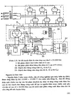
Basic Geotechnical Earthquake Phần 4 docx
Bạn đang xem bản rút gọn của tài liệu. Xem và tải ngay bản đầy đủ của tài liệu tại đây (397.84 KB, 16 trang )
38 Basic Geotechnical Earthquake Engineering
38
DYNAMIC SOIL PROPERTIES
4
CHAPTER
4.1 INTRODUCTION
This book is concerned with geotechnical problems associated with dynamic loads. It
also deals with earthquake related ground motion as well as soil response induced by earthquake
loads. The dynamic response of foundations and structures depends on the magnitude, frequency,
direction, and location of the dynamic loads. Furthermore, it also deals with the geometry of
the soil-foundation contact system, as well as the dynamic properties of the supporting soils
and structures.
Elements in a seismic response analysis are: input motions, site profile, static soil
properties, dynamic soil properties, constitutive models of soil response to loading and methods
of analysis using computer programs. The contents include: earthquake response spectra; site
seismicity; soil response to seismic motion, design earthquake, seismic loads on structures,
liquefaction potential, lateral spread from liquefaction, and foundation base isolation.
Some special problems in geotechnical engineering dealing with soil dynamics and
earthquake aspects are discussed in the later chapters. Its contents include: liquefaction
potential of soil, foundation settlement, dynamic bearing capacity of foundations, stone columns
and displacement piles, dynamic slope stability and dynamic earth pressure in the context of
earthquake loading.
4.2 SOIL PROPERTIES FOR DYNAMIC LOADING
The properties that are most important for dynamic analyses are the stiffness, material
damping, and unit weight. These properties enter directly into the computations of dynamic
response. In addition, the location of the water table, degree of saturation, and grain size
distribution may be important, especially when liquefaction is a potential problem. Since
earthquake induces dynamic kind of loading into the soil, these dynamic soil properties are
quite significant.
Dynamic Soil Properties 39
One method of direct determination of dynamic soil properties in the field is to measure
the velocity of shear waves in the soil. The waves are generated by impacts produced by a
hammer or by detonating charges of explosives. Then the Travel times are recorded. This is
usually done in or between bore holes. A rough correlation between the number of blows per
foot in standard penetration tests and the velocity of shear waves is shown in Fig. 4.1.
Standard penetration test is well known test in foundation engineering.
Fig. 4.1 Relation between number of blows per foot in standard penetration test and velocity of shear waves
(Courtesy: <>)
4.3 TYPES OF SOILS
As in other areas of soil mechanics, the type of the soil affects its response under
dynamic loading conditions. Furthermore, it also determines the type of dynamic problems
that must be analyzed. The most significant factors separating different types of soils is the
grain size distribution. The presence or absence of clay fraction in soil system, as well as the
degree of saturation of soil system also plays key role in this connection. It is also important
to know whether the dynamic loading is a transient phenomenon, such as a blast loading or
earthquake, or is a long term phenomenon, like a vibratory loading from rotating machinery.
The distinction is important because a transient dynamic phenomenon occurs so rapidly that
excess pore pressure does not have time to dissipate. Dissipation of pore water is possible
only in the case of very coarse, clean gravels if dynamic loading is a transient dynamic
phenomenon. In this context the length of the drainage path is also important. Even a clean,
40 Basic Geotechnical Earthquake Engineering
granular material may retain large excess pore pressure if the drainage path is so long that
the pressures cannot dissipate during the dynamic loading. Consequently, it is necessary to
categorize the soil by asking the following questions:
(a) Is the material saturated? If it is saturated, a transient dynamic loading will usually
last for very short duration. The duration is so short that the soil’s response is
essentially undrained. If it is not saturated, the response to dynamic loadings will
probably include some volumetric component as well.
(b) Are there fines present in the soil? The presence of fines, especially clays inhibits the
dissipation of excess pore pressure. It also decreases the tendency for liquefaction.
(c) How dense is the soil? Dense soils are not likely to collapse under dynamic loads.
On the other hand, Loose soils may collapse under dynamic loads. Furthermore,
Loose soils may densify under vibratory loading and cause permanent settlements.
(d) How are the grain sizes distributed? Well graded materials are less susceptible to
losing strength under dynamic loading. On the other hand Uniform soils are more
susceptible to losing strength under dynamic loading. Loose, Uniform soils are especially
subject to collapse and failure under dynamic loading.
4.3.1 Dry and Partially Saturated Cohesionless Soils
There are three types of dry or partially saturated Cohesionless Soils The first type
comprises soils that consist essentially of small-sized to medium-sized grains of sufficient
strength or under sufficiently small stress condition. The grain breakage does not play a
significant role in their behavior. The second type includes those soils made up essentially
of large-sized grains, such as rockfills. Large-sized grains may break under large stresses.
Overall volume changes are significantly conditioned by grain breakage. The third type
includes fine-grained materials, such as silt. The behavior of the first type of dry cohesionless
soils can be described in terms of the critical void ratio. The behavior of the second type
depends on the normal stresses and grain size. If the water or air cannot escape at a
sufficiently fast rate when the third type of soil is contracting due to vibration under
dynamic loading, significant pore pressures may develop. Consequently liquefaction of the
material is likely.
4.3.2 Saturated Cohesionless Soils
If pore water can flow in and out of the material at a sufficiently high rate, pore
pressures do not develop. Consequently, behavior of these soils does not differ qualitatively
from that of partially saturated cohesionless soils. If the pore water cannot flow in or out of
the material, cyclic loads under dynamic load will usually generate increased pore pressure.
If the soil is loose or contractive, the soil may liquefy.
4.3.3 Saturated Cohesive Soils
Alternating loads decrease the strength and stiffness of cohesive soils. The decrease
depends on the number of repetitions. It also depends on the relative values of sustained
and cycling stresses as well as on the sensitivity of the soil. Very sensitive clays may lose so
Dynamic Soil Properties 41
much of their strength that there may be a sudden failure. The phenomenon is associated
with a reduction in effective pressure as was the case with cohesionless soils.
4.3.4 Partially Saturated Cohesive Soils
The discussion in connection with saturated Cohesive soils, are applied to insensitive
soils as well, when they are partially saturated, except that the possibility of liquefaction
seems remote in the later kind of soil.
4.4 MEASURING DYNAMIC SOIL PROPERTIES
Soil properties to be used in dynamic analyses can be measured in the field. These
properties can also be measured in the laboratory. In many important applications, a combination
of field and laboratory measurements are used.
4.4.1 Field Measurements of Dynamic Modulus
Direct measurement for soil or rock stiffness in the field has the advantage of minimal
material disturbance. The modulus is measured where the soil exists. Furthermore, the measurements
are not constrained by the size of a sample.
Moduli measured in the field correspond to very small strains. Some procedures for
measuring moduli at large strain have also been proposed. However, none has been found
fully satisfactory by the geotechnical engineering community. The dissipation of energy during
strain, which is called material damping, requires significant strains to occur. Consequently,
field techniques have failed to prove effective in measuring material damping.
In situ techniques are based on measurement of the velocity of propagation of stress
waves through the soil. The P-waves or compression waves are dominated by the response of
the pore fluid in the saturated soils. Consequently, most techniques measure the S-waves or
shear waves. If the velocity of the shear wave through a soil deposit is determined to be V
s
,
the shear modulus G is given as:
G=
22
VV
g
ss
γ
ρ=
(4.1)
where, ρ = mass density of soil.
γ = unit weight of soil.
g = acceleration of gravity.
There are three techniques for measuring shear wave velocity in in-situ soil. These
techniques are as follows: cross-hole, down-hole, and uphole. All the three techniques require
boring to be made in the in-situ soil.
In the cross-hole method sensors are placed at one elevation in one or more borings.
Then a source of energy is triggered in another boring at the same elevation. The waves travel
horizontally from the source to the receiving holes. The arrivals of the S-waves are noted on
the traces of the response of the sensors. The velocity of S-wave can be calculated by dividing
42 Basic Geotechnical Earthquake Engineering
the distance between borings by the time for a wave to travel between them. However, it is
difficult to establish the exact triggering time. Consequently, the most accurate measurements
are obtained from the difference of arrival times at two or more receiving holes rather than
from the time between the triggering and the arrival at single hole.
P-waves travel faster than S-waves. Consequently, the sensors will already be excited by
the P-waves when the S-waves arrive. This can make it difficult to pick out the arrival of the
S-wave. To alleviate this difficulty it is desirable to use an energy source that is rich in the
vertical shear component of motion and relatively poor in compressive motion. Several devices
are available that do this. The original cross-hole velocity measurement methods used explosives
as the source of energy. These were rich in compression energy and poor in shear energy.
Consequently, it is quite difficult to pick out the S-wave arrivals in this case. Hence, explosives
should not be used as energy sources for cross-hole S-wave velocity measurements. ASTM D
4428/D 4428M, Cross-Hole Seismic Testing, describes the details of this test.
In the down-hole method the sensors are placed at various depths in the boring.
Furthermore, the source of energy is above the sensors - usually at the surface. A source rich
in S-waves should be used. This technique does not require as many borings as the cross-hole
method. However, the waves travel through several layers from the source to the sensors.
Thus, the measured travel time reflects the cumulative travel through layers with different
wave velocities. Interpreting the data requires sorting out the contribution of the layers. The
seismocone version of the cone penetration test is one example of the down-hole method.
In the up-hole method the source of the energy is deep in the boring. The sensors are
above it—usually at the surface.
A recently developed technique that does not require borings is the spectral analysis
of surface waves (SASW). This technique uses sensors that are spread out along a line at the
surface. The source of energy is a hammer or tamper also located at the surface. The surface
excitation generates surface waves. In particular, they are Rayleigh waves. These are waves
that occur because of the difference in stiffness between the soil and the overlying air. The
particles move in retrograde ellipses and their amplitudes decay from the surface. The test
results are interpreted by recording the signals at each of the receiving stations. Computer
program is used to perform the spectral analysis of the data. Computer programs have been
developed that will determine the shear wave velocities from the results of the spectral
analysis.
The SASW method is most effective for determining properties near the surface. In
order to increase the depth of the measurements, the energy at the source must also be
increased. Measurements for the few feet below the surface, which may be adequate for
evaluating pavements, can be accomplished with a sledge hammer as a source of energy.
However, measurements several tens of feet deep require track-mounted seismic “pingers.”
The SASW method works best in cases where the stiffness of the soils and rocks increases
with depth. If there are soft layers lying under stiff ones, the interpretation may be ambiguous.
A soft layer lying between stiff ones can cause problems for the crosshole method as well.
Reason being that the waves will travel fastest through the stiff layers and the soft layer may
be masked.
Dynamic Soil Properties 43
The cross-hole, down-hole, and up-hole methods may not work well very near the surface.
Complications due to surface effects may affect the readings while using aforementioned methods.
This is the region where the SASW method should provide the best result. The crosshole
technique employs waves with horizontal particle motion. The down-hole and up-hole methods
use waves whose particle motions are vertical or nearly so. Surface waves in the SASW method
have particle motions in all the sensors. Therefore, a combination of these techniques can be
expected to give a more reliable picture of the shear modulus than any one used alone.
4.4.2 Laboratory Measurement of Dynamic Soil Properties
Laboratory measurements of soil properties can be used to supplement or confirm the
results of field measurements. They can also be necessary to establish values of damping and
modulus at strains larger than those that can be attained in the field. Furthermore, they are
also used to measure the properties of materials that do not presently exist in the field.
Example is soil to be compacted.
A large number of laboratory tests for dynamic purposes have been developed. Research
is continuing in this area. These tests can generally be classified into two groups. First group
of tests are those that apply dynamic loads. Second group of tests are those that apply loads
that are cyclic but slow enough that inertial effects do not occur.
The most widely used of the laboratory tests that apply dynamic loads is the resonant-
column method. In this test a column of soil is subjected to an oscillating longitudinal or
torsional load. The frequency is varied until resonance occur. From the frequency and amplitude
at resonance the modulus and damping of the soil can be calculated. A further measure of
the damping can be obtained by observing the decay of oscillations when the load is cut off.
ASTM D 4015 describes only one type of resonant-column device. However, there
are several types that have been developed. These devices provide measurements of both
modulus and damping at low strain levels. The strains can sometimes be raised a few
percent. However, they remain essentially low strain devices. These devices could be of
torsional or of longitudinal type. The torsional devices give measurements on shear behavior.
On the other hand, the longitudinal devices give measurements pertaining to extension and
compression behavior.
The most widely used of the cyclic loading laboratory tests is the cyclic triaxial test. In
this test a cyclic load is applied to a column of soil over a number of cycles. Cyclic load
application is slow, such that inertial effects do not occur. The response at one amplitude of
load is observed. Afterwards, the test is repeated at a higher load. Fig. 4.2(A) shows the
typical pattern of stress and strain. It is expressed as shear stress and shear strain. The shear
modulus is the slope of the secant line inside the loop in Fig. 4.2(A). The critical damping
ratio, D, is:
where, D =
i
T
A
4A
π
(4.2)
A
i
= area of loop
A
t
= shaded area
44 Basic Geotechnical Earthquake Engineering
Other types of cyclic loading devices also exist. Cyclic simple shear devices are such
devices. Their results are interpreted similarly. These devices load the sample to levels of
strain much larger than those attainable in the resonant column devices. A major problem in
both resonant-column and cyclic devices is the difficulty of obtaining undisturbed samples.
This is especially true for small-strain data. Reason being that the effects of sample disturbance
are particularly apparent at small strains.
The results of laboratory tests are often presented in a form similar to Fig. 4.2 (B-1 and
B-2). In Fig. 4.2 (B-1) the ordinate is the secant modulus divided by the modulus at small
strains. In Fig. 4.2 (B-2) the ordinate is the value of the initial damping ratio. Both are
plotted against the logarithm of the cyclic strain level.
Fig. 4.2 Laboratory measurement of dynamic soil properties
(Courtesy:
<>)
τ
A
1
= Area of Loop
G
0
G
A
T
γ
D =
A
1
4π A
T
(A) Typical Pattern of Shear Stress and Shear Strain
1
0.9
0.8
0.7
0.6
0.5
0.4
0.3
0.2
0.1
0
1
0.9
0.8
0.7
0.6
0.5
0.4
0.3
0.2
0.1
0
G
G
0
0.000010.0001 0.001 0.01 0.1 1
γ
(B-1) Cyclic Shear Strain vs. the Ratio of secant
Modulus and the Modulus of Small Strain
0.000010.0001 0.001 0.01 0.1 1
γ
(B-2) Cyclic Shear Strain vs. the Value
of Initial Damping Ratio
Dynamic Soil Properties 45
Home Work Problems
1. The shear moduli of steel and its specific gravity is 11.5 × 10
6
psi and 7.85 respectively.
Determine shear wave velocity through it. (Ans. 10434 ft/sec)
2. The type of the soil affects its response under dynamic loading conditions. Justify the statement.
3. Explain about standard techniques for measuring shear wave velocity in in-situ soil.
4. Explain about cyclic triaxial testing. How shear modulus and critical damping ratio is determined
using cyclic triaxial testing.
46 Basic Geotechnical Earthquake Engineering
SITE SEISMICITY, SEISMIC SOIL RESPONSE
AND DESIGN EARTHQUAKE
5
CHAPTER
5.1 SITE SEISMICITY
5.1.1 Site Seismicity Study
The objective of a seismicity study is to quantify the level and characteristics of ground
motion shaking associated with earthquake that pose a risk to a given site of interest. A
seismicity study starts with detailed examination of available geological, historical, and seismological
data. These data are used to establish patterns of seismicity. They are also used to locate
possible sources of earthquakes and their associated mechanisms. The site seismicity study
produces a description of the earthquake for which facilities must be designed. In many
cases, this will take the form of a probability distribution of expected site acceleration (or
other measurements of ground motion) for a given exposure period. It will also give an
indication of the frequency content of that motion. In some cases typical ground motion time
histories called scenario earthquakes are developed. One approach is to use the historical
epicenter database in conjunction with available geological data. These data are used to form
a best estimate regarding the probability of site ground motion.
Fig. 5.1 explains some terms that are commonly used in seismic hazard analysis. The
“hypocenter” or “focus” is the point at which the motions originated. This is usually the point
on the causative fault. This is the point at which the first sliding occurs. It is not necessarily
the point from which greatest energy is propagated. The “epicenter” is the point on the
ground surface that lies directly above the focus. The “focal depth” is the depth of the focus
below the ground surface. The “epicentral distance” is the distance from the epicenter to the
point of interest on the surface of the earth. These aspects have been discussed in Chapter
2 also.
As a part of the Navy’s seismic hazard mitigation program, procedures were developed
in the form of a computer program (named SEISMIC, NAVFACENGCOM technical report
46
Site Seismicity, Seismic Soil Response and Design Earthquake 47
TR-2016-SHR, procedures for computing site seismicity, and acceleration in rock for earthquakes
in the western united states). The program was designed to run on standard desktop DOS-
based computers. The procedures consist of:
(a) Evaluating tectonics and geologic settings.
(b) Specifying faulting sources.
(c) Determining site soil conditions.
(d) Determining the geologic slip rate data.
(e) Specifying the epicenter search area and search of database.
(f) Specifying and formulating the site seismicity model.
(g) Developing the recurrence model.
(h) Determining the maximum source events.
(i) Selecting the motion attenuation relationship.
(j) Computing individual fault/source seismic, contributions.
(k) Summing the effects of the sources.
(l) Determining the site matched spectra for causative events.
Fig. 5.1 Definition of earthquake terms (Courtesy: <>)
5.1.2 Ground Motion Estimates
Ground motion attenuation equations are used to determine the level of acceleration
as a function of distance from the source as well as the magnitude of the earthquake.
Correlations have been made between peak acceleration and other descriptions of ground
motion with distance for various events. These equations allow the engineers to estimate the
ground motions at a site from a specified event. They also allow engineers to find out the
uncertainty associated with the estimate. There are a number of attenuation equations that
Epicenter
Epicentral distnace, ∆
SOIL
ROCK
ROCK
Hypocenter
Focal Depth
Fault
48 Basic Geotechnical Earthquake Engineering
have been developed by various researchers. Donovan and Bornstein, 1978, developed the
following equation for peak horizontal acceleration. Equations were developed from the
western united states data.
Y = (a)(exp(bM))(r + 25)
d
(5.1a)
a = (2,154,000)(r)
–2.10
(5.1b)
b = (0.046)+(0.445)log(r) (5.1c)
d = (2.515)+(0.486)log(r) (5.1d)
where, Y = peak horizontal acceleration (in gal) (1 gal = 1 cm/sec
2
)
M = earthquake magnitude
r = distance (in km) to energy center, default at a depth of
5 km.
5.1.3 Analysis Techniques
NAVFAC P355.1, seismic design guidelines for essential buildings provides instructions
for site seismicity studies. These studies are used for determining ground motion and response
spectra. An automated procedure has been developed by NFESC (Naval Facilities Engineering
Service Center) to perform a seismic analysis. The analysis has been done using available
historic and geological data to compute the probability of occurrence of acceleration at a
given site. A regional study is first performed in which all of the historic epicenters are used
with an attenuation relationship. This study is used to compute the site acceleration for all
historic earthquakes. A regression analysis is performed to obtain regional recurrence coefficients,
and a map of epicenters is plotted. Confidence bounds are given on the site acceleration as
a function of probability of exceedance.
5.2 SEISMIC SOIL RESPONSE
5.2.1 Seismic Response of Horizontally Layered Soil Deposits
Several methods for evaluating the effect of local soil conditions on ground response
during earthquakes are now available. Most of these methods are based on the assumption
that the main responses in a soil deposit are caused by the upward propagation of horizontally
polarized shear waves (SH waves). These waves are propagated from the underlying rock
formation. Analytical procedures based on this concept incorporating linear approximation to
nonlinear soil behavior, have been shown to give results in fair agreement with field observations
in a number of cases. Accordingly, engineers are finding increasing use in earthquake engineering
for predicting response within soil deposits and the characteristics of ground surface motions.
5.2.2 Evaluation Procedure
The analytical procedure generally involves the following steps:
(a) Determine the characteristics of the motions likely to develop in the rock formation
underlying the site. After that select an accelerogram with these characteristics for
Site Seismicity, Seismic Soil Response and Design Earthquake 49
use in the analysis. The maximum acceleration, predominant period, and effective
duration are the most important parameters of an earthquake motion. Empirical
relationships between these parameters and the distance from the causative fault to
the site have been established for earthquakes of different magnitudes. A design
motion with the desired characteristics can be selected from the strong motion
accelerograms that have been recorded during previous earthquakes or from artificially
generated accelerograms.
(b) Determine the dynamic properties of the soil deposit. Average relationships between
the dynamic shear moduli, as functions of shear strain and static properties, have
been established for various soil types (Seed and Idriss, 1970). Average relation
between the damping ratios of soils, as functions of shear strain and static properties
have also been established. Thus a testing program to obtain the static properties for
use in these relationships will often serve to establish the dynamic properties with
a sufficient degree of accuracy. However more elaborate dynamic testing procedures
are required for special problems. These techniques are also needed for soil types
for which empirical relationships with static properties have not been established.
(c) Compute the response of the soil deposit to the base rock motions. A one-dimensional
method of analysis can be used if the soil structure is essentially horizontal. Computer
programs developed for performing this analysis are generally based on either the
solution to the wave equation or on a lumped mass simulation. More irregular soil
deposits may require a finite element analysis.
5.2.3 Analysis Using Computer Program
A computer program SHAKE, which is based on the one dimensional wave propagation
method is available. The program can compute the responses for a design motion given
anywhere in the system. Thus acceleration obtained from instruments on soil deposits can be
used to generate new rock motions which, in turn, can be used as design motion for other
soil deposits. Fig. 5.2 shows schematic representation of the procedure for computing effects
of local soil conditions on ground motions. If the ground motions are known or specified at
Point A, the SHAKE program can be used to compute the motion to the base of the soil
column. That is, the program finds the base rock motion that causes the motion at Point A.
The program can then find what the motion would be at a rock outcrop if the base rock
motion had been propagated upward through rock instead of soil. This rock outcrop motion
is then used as input to an amplification analysis, yielding the motion at Point B. From
Fig. 5.2 it is clear that it is the top of another soil column.
The program also incorporates a linear approximation to nonlinear soil behavior. Furthermore,
it also incorporates the effect of the elasticity of the base rock, and systems with different
values of damping and modulus in different layers. Other versions of the same sort of
analysis, often incorporating other useful features, are also available and may be superior to
the original version of SHAKE. A NAVFAC sponsored MSHAKE microcomputer program
was developed in 1994. The MSHAKE is a user friendly implementation of the SHAKE91
program which is a modified version of the original computer program SHAKE.
50 Basic Geotechnical Earthquake Engineering
Fig. 5.2 Schematic representation of procedure for computing effects of local soil conditions on
ground motions (Courtesy:
<>)
5.3 DESIGN EARTHQUAKE
5.3.1 Design Parameters
In evaluating the soil behavior under earthquake motion, it is necessary to know the
magnitude of the earthquake. It is also necessary to describe the ground motion in terms that
can be used for further engineering analysis. Historically, design earthquake waves were
specified in terms of the peak acceleration. However, more modern techniques use the
response spectrum or one or more time histories of motion. It has been concluded that the
most reliable method for accomplishing this is to base the studies on data obtained at the
site. A second choice is to find another site similar in geologic and seismic setting where
ground motion was measured during a design level magnitude earthquake. However, this will
usually not be possible, and estimates of ground motion based on correlations and geologic
and seismologic evidence for the specific site will become necessary.
Factors Affecting Ground Motion: Factors that affect strong ground motion include:
(a) Wave types—S and P waves that travel through the earth, as well as the surface
waves that propagate along the surfaces or interfaces.
(b) Earthquake magnitude—There are several magnitude scales. Even a small magnitude
event may produce large accelerations in the near field. Consequently, a wide variety
of acceleration for the same magnitude may be expected.
Recorded
Ground
Motion
Rock
Outorop
Motion
Modified
Rock
Outorop
Motion
A
Soil Layers
Possible Change
in Amplitude of
Rock Outcrop Motion
Depending on Distnace
of Energy Release
Modified
Ground
Mortion
B
Soil Layers
Base
Rock
Motion
Modified
Base Rock
Motion
Rock
Site Seismicity, Seismic Soil Response and Design Earthquake 51
(c) Distance from epicenter or from center of energy release.
(d) Site conditions.
(e) Fault type, depth, and the recurrence interval.
Fig. 5.3 Example of attenuation relationships in rock (Courtesy: )
52 Basic Geotechnical Earthquake Engineering
Fig. 5.4 approximate relationship for maximum acceleration in various soil conditions knowing maximum
acceleration in rock (Courtesy: )
Ground Motion Parameters
Ground motion parameters have been correlated with magnitude and distance. These
correlations have been developed by several investigators. The correlation in Fig. 5.3 (Schnabel
and Seed, 1973), is based on ground motion records from the Western United States. Furthermore,
it is believed to be more applicable to small and moderate earthquakes (magnitudes 5.5 and
6.5) for rock. This correlation is also statistically applicable for stiff soil sites (e.g., where
overburden is of stiff clays and dense sands less than 150 feet thick). For other site conditions,
motion may occur as illustrated in Fig. 5.4 (Relationship between maximum acceleration,
Site Seismicity, Seismic Soil Response and Design Earthquake 53
maximum velocity, distance from source and local site conditions for moderately strong earthquake,
seed, murnaka, lysmer, and idris, 1975).
5.3.2 Site Specific Studies
In areas where faults are reasonably mapped and studied, site specific investigations
can verify if such faults are trending towards the site or the facility is on an active fault.
Studies may involve trenching, mapping, geophysical measurements, as well as other investigation
techniques. The extent of the area to be investigated depends on geology. It also depends on
the type and use of the structure. In some localities, state, or local building codes establish
minimum setback distances from active faults. Unless other critical conditions demand differently,
300 feet of minimum distance from an active fault is provided. For essential facilities the
distance should be increased appropriately.
There could be faults in seismically active areas where faults are not well mapped.
Under these conditions, site specific investigations may be required. Regional investigations
may also be required. Other hazards to be considered in a site investigation include the
potential for liquefaction and sliding.
5.3.3 Earthquake Magnitude
Design earthquake magnitude as well as the selection of magnitude level are discussed
below:
Design Earthquake Magnitude
Engineers can define a design earthquake for a site in terms of the earthquake magnitude,
M. It is also defined in terms of the strength of ground motion. Factors influencing the
selection of a design earthquake are the length of geologic fault structures, relationship
between the fault and the regional tectonic structure, the rate of displacement across the
fault, the geologic history of displacement along the structure, and the seismic history of the
region.
The design earthquake in engineering terms is a specification of levels of ground
motion. At this level of ground motion, the structure is required to survive successfully with
no loss of life, acceptable damage, or no loss of service. A design earthquake on a statistical
basis considers the probability of the recurrence of a historical event.
Earthquake magnitudes can be specified in terms of a design level earthquake.
This level of earthquake can reasonably be expected to occur during the life of the
structure. As such, this represents a service load that the structure must withstand
without significant structural damage or interruption of a required operation. A second
level of earthquake magnitude is a maximum credible event for which the structure
must not collapse. However, significant structural damage can occur. The inelastic behavior
of the structure must be limited to ensure the prevention of collapse and catastrophic
loss of life during earthquake.