CAVITATION AND BUBBLE DYNAMICS Part 3 doc
Bạn đang xem bản rút gọn của tài liệu. Xem và tải ngay bản đầy đủ của tài liệu tại đây (347 KB, 20 trang )
Chapter 1 - Cavitation and Bubble Dynamics - Christopher E. Brennen
This is because air dissolved in the liquid will tend to come out of solution at low pressures
and contribute a partial pressure of air to the contents of any macroscopic cavitation bubble.
When that bubble is convected into regions of higher pressure and the vapor condenses, this
leaves a small air bubble that only redissolves very slowly, if at all. This unforeseen
phenomenon caused great trauma for the first water tunnels, which were modeled directly on
wind tunnels. It was discovered that after a few minutes of operating with a cavitating body
in the working section, the bubbles produced by the cavitation grew rapidly in number and
began to complete the circuit of the facility to return in the incoming flow. Soon the working
section was obscured by a two-phase flow. The solution had two components. First, a water
tunnel needs to be fitted with a long and deep return leg so that the water remains at high
pressure for sufficient time to redissolve most of the cavitation-produced nuclei. Such a
return leg is termed a ``resorber.'' Second, most water tunnel facilities have a ``deaerator'' for
reducing the air content of the water to 20 to 50% of the saturation level. These comments
serve to illustrate the fact that N(R
N
) in any facility can change according to the operating
condition and can be altered both by deaeration and by filtration.
One of the consequences of the effect of cavitation itself on the nuclei population in a facility
is that the cavitation number at which cavitation disappears when the pressure is raised may
be different from the value of the cavitation number at which it appeared when the pressure
was decreased. The first value is termed the ``desinent'' cavitation number and is denoted by
σ
d
to distinguish it from the inception number, σ
i
. The difference in these values is termed
``cavitation hysteresis'' (Holl and Treaster 1966).
One of the additional complications is the subjective nature of the judgment that cavitation
has appeared. Visual inspection is not always possible, nor is it very objective since the
number of events (single bubble growth and collapse) tends to increase gradually over a
range of cavitation numbers. If, therefore, one made a judgment based on a certain event rate,
it is inevitable that the inception cavitation number would increase with nuclei population.
Experiments have found that the production of noise is a simpler and more repeatable
measure of inception than visual observation. While still subject to the variations with nuclei
population discussed above, it has the advantage of being quantifiable.
Most of the data of Figure 1.8 is taken from water tunnel water that has been somewhat
filtered and degassed or from the ocean, which is surprisingly clean. Thus there are very few
nuclei with a size greater than 100•m. On the other hand, there are many hydraulic
applications in which the water contains much larger gas bubbles. These can then grow
substantially as they pass through a region of low pressure in the pump or other hydraulic
device, even though the pressure is everywhere above the vapor pressure. Such a
phenomenon is called ``pseudo-cavitation.'' Though a cavitation inception number is not
particularly relevant to such circumstances, attempts to measure σ
i
under these circumstances
would clearly yield values much larger than -C
pmin
.
On the other hand, if the liquid is quite clean with only very small nuclei, the tension that this
(27 of 33)7/8/2003 3:54:07 AM
Chapter 1 - Cavitation and Bubble Dynamics - Christopher E. Brennen
liquid can sustain would mean that the minimum pressure would have to fall well below p
V
for inception to occur. Then σ
i
would be much smaller than -C
pmin
. Thus it is clear that the
quality of the water and its nuclei could cause the cavitation inception number to be either
larger or smaller than -C
pmin
.
1.16 CAVITATION INCEPTION DATA
Though much of the inception data in the literature is deficient in the sense that the nuclei
population and character are unknown, it is nevertheless of value to review some of the
important trends in that data base. In doing so we could be reassured that each investigator
probably applied a consistent criterion in assessing cavitation inception. Therefore, though
the data from different investigators and facilities may be widely scattered, one would hope
that the trends exhibited in a particular research project would be qualitatively significant.
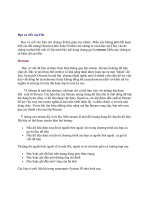
Figure 1.12 Cavitation inception characteristics of a NACA 4412 hydrofoil (Kermeen
1956).
Consider first the inception characteristics of a single hydrofoil as the angle of attack is
varied. The data of Kermeen (1956), obtained for a NACA 4412 hydrofoil, is reproduced in
Figure 1.12. At positive angles of attack the regions of low pressure and cavitation inception
(28 of 33)7/8/2003 3:54:07 AM
Chapter 1 - Cavitation and Bubble Dynamics - Christopher E. Brennen
will occur on the suction surface; at negative angles of attack these phenomena will shift to
the pressure surface. Furthermore, as the angle of attack is increased in either direction, the
value of -C
pmin
will increase, and hence the inception cavitation number will also increase.
As we will discuss in the next section, the scaling of cavitation inception with changes in the
size and speed of the hydraulic device can be an important issue, particularly when scaling
the results from model-scale water tunnel experiments to prototypes as is necessary, for
example, in developing ship propellers. Typical data on cavitation inception for a single
hydrofoil (Holl and Wislicenus 1961) is reproduced in Figure 1.13. Data for three different
sizes of 12% Joukowski hydrofoil (at zero angle of attack) were obtained at different speeds.
They were plotted against Reynolds number in the hope that this would reduce the data to a
single curve. The fact that this did not occur demonstrates that there is a size or speed effect
separate from that due to the Reynolds number. It seems reasonable to suggest that the
missing parameter is the ratio of the nuclei size to chord length; however, in the absence of
information on the nuclei, such conclusions are purely speculative.
Figure 1.13 The desinent cavitation numbers for three sizes of Joukowski hydrofoils at zero
angle of attack and as a function of Reynolds number, Re (Holl and Wislicenus 1961). Note
the theoretical C
pmin
=-0.54.
To complete the list of those factors that may influence cavitation inception, it is necessary to
mention the effects of surface roughness and of the turbulence level in the flow. The two
effects are connected to some degree since roughness will affect the level of turbulence. But
(29 of 33)7/8/2003 3:54:07 AM
Chapter 1 - Cavitation and Bubble Dynamics - Christopher E. Brennen
roughness can also affect the flow by delaying boundary layer separation and therefore
affecting the pressure and velocity fields in a more global manner. The reader is referred to
Arndt and Ippen (1968) for details of the effects of surface roughness on cavitation inception.
Turbulence affects cavitation inception since a nucleus may find itself in the core of a vortex
where the pressure level is lower than the mean. It could therefore cavitate when it might not
do so under the influence of the mean pressure level. Thus turbulence may promote
cavitation, but one must allow for the fact that it may alter the global pressure field by
altering the location of flow separation. These complicated viscous effects on cavitation
inception were first examined in detail by Arakeri and Acosta (1974) and Gates and Acosta
(1978) (see also Arakeri 1979). The implications for cavitation inception in the highly
turbulent environment of many internal flows such as occur in pumps have yet to be
examined in detail.
1.17 SCALING OF CAVITATION INCEPTION
The complexity of the issues raised in the last section helps to explain why serious questions
remain as to how to scale cavitation inception. This is perhaps one of the most troublesome
issues a hydraulic engineer must face. Model tests of a ship's propeller or large pump-turbine
may allow the designer to accurately estimate the noncavitating performance of the device.
However, he will not be able to place anything like the same confidence in his ability to scale
the cavitation inception data.
Consider the problem in more detail. Changing the size of the device will alter not only the
residence time effect but also the Reynolds number. Furthermore, the nuclei will now be a
different size relative to the device than in the model. Changing the speed in an attempt to
maintain Reynolds number scaling may only confuse the issue by further alterating the
residence time. Moreover, changing the speed will also change the cavitation number. To
recover the modeled condition, one must then change the pressure level, which may alter the
nuclei content. There is also the issue of what to do about the surface roughness in the model
and in the prototype.
The other issue of scaling that arises is how to anticipate the cavitation phenomena in one
liquid based on data obtained in another. It is clearly the case that the literature contains a
great deal of data on water. Data on other liquids are quite meager. Indeed, I have not located
any nuclei number distributions for a fluid other than water. Since the nuclei play such a key
role, it is not surprising that our current ability to scale from one liquid to another is quite
tentative.
It would not be appropriate to leave this subject without emphasizing that most of the
remarks in the last two sections have focused on the inception of cavitation. Once cavitation
has become established, the phenomena that occur are much less sensitive to special factors
such as the nuclei content. Hence the scaling of developed cavitation can proceed with much
more confidence than the scaling of cavitation inception. This is not, however, of much
(30 of 33)7/8/2003 3:54:07 AM
Chapter 1 - Cavitation and Bubble Dynamics - Christopher E. Brennen
solace to the engineer charged with avoiding cavitation completely.
REFERENCES
● Acosta, A.J. and Parkin, B.R. (1975). Cavitation inception a selective review. J.
Ship Res., 19, 193 205.
● Arakeri, V.H. (1979). Cavitation inception. Proc. Indian Acad. Sci., C2, Part 2, 149
177.
● Arakeri, V.H. and Acosta, A.J. (1974). Viscous effects in the inception of cavitation
on axisymmetric bodies. ASME J. Fluids Eng., 95, No. 4, 519 528.
● Arndt, R.E.A. and Ippen, A.T. (1968). Rough surface effects on cavitation inception.
ASME J. Basic Eng., 90, 249 261.
● Becker, R. and Doring, W. (1935). The kinetic treatment of nuclear formation in
supersaturated vapors. Ann. Phys., 24, 719 and 752.
● Bernath, L. (1952). Theory of bubble formation in liquids. Ind. Eng. Chem., 44, No. 6,
1310 1313.
● Berthelot, M. (1850). Sur quelques phenomenes de dilation forcee de liquides. Ann. de
Chimie et de Physique, 30, 232 237.
● Billet, M.L. (1985). Cavitation nuclei measurement a review. Proc. 1985 ASME
Cavitation and Multiphase Flow Forum, 31 38.
● Blake, F.G. (1949). The tensile strength of liquids; a review of the literature. Harvard
Acou. Res. Lab. Rep. TM9.
● Blander, M. and Katz, J.L. (1975). Bubble nucleation in liquids. AIChE Journal, 21,
No. 5, 833 848.
● Carey, V.P. (1992). Liquid-vapor phase-change phenomena. Hemisphere Publ. Co.
● Cole, R. (1970). Boiling nucleation. Adv. Heat Transfer, 10, 86 166.
● Davies, R.M., Trevena, D.H., Rees, N.J.M., and Lewis, G.M. (1956). The tensile
strength of liquids under dynamic stressing. Proc. N.P.L. Symp. on Cavitation in
Hydrodynamics.
● Dixon, H.H. (1909). Note on the tensile strength of water. Sci. Proc. Royal Dublin
Soc., 12, (N.S.), 60 (see also 14, (N.S.), 229, (1914)).
● Eberhart, J.G. and Schnyders, M.C. (1973). Application of the mechanical stability
condition to the prediction of the limit of superheat for normal alkanes, ether, and
water. J. Phys. Chem., 77, No. 23, 2730 2736.
● Farkas, L. (1927). The velocity of nucleus formation in supersaturated vapors. J.
Physik Chem., 125, 236.
● Fox, F.E. and Herzfeld, K.F. (1954). Gas bubbles with organic skin as cavitation
nuclei. J. Acoust. Soc. Am., 26, 984 989.
● Frenkel, J. (1955). Kinetic theory of liquids. Dover, New York.
● Gates, E.M. and Acosta, A.J. (1978). Some effects of several free stream factors on
cavitation inception on axisymmetric bodies. Proc. 12th Naval Hydrodyn. Symp.,
Wash. D.C., 86 108.
● Gates, E.M. and Bacon, J. (1978). Determination of cavitation nuclei distribution by
holography. J. Ship Res., 22, No. 1, 29 31.
(31 of 33)7/8/2003 3:54:07 AM
Chapter 1 - Cavitation and Bubble Dynamics - Christopher E. Brennen
● Gibbs, W. (1961). The Scientific Papers, Vol. 1. Dover Publ. Inc., NY.
● Griffith, P. and Wallis, J.D. (1960). The role of surface conditions in nucleate boiling.
Chem. Eng. Prog. Symp., Ser. 56, 30, 49.
● Harvey, E.N., Barnes, D.K. , McElroy, W.D., Whiteley, A.H., Pease, D.C., and
Cooper, K.W. (1944). Bubble formation in animals. I, Physical factors. J. Cell. and
Comp. Physiol., 24, No. 1, 1 22.
● Holl, J.W. and Wislicenus, G.F. (1961). Scale effects on cavitation. ASME J. Basic
Eng., 83, 385 398.
● Holl, J.W. and Treaster, A.L. (1966). Cavitation hysteresis. ASME J. Basic Eng., 88,
199 212.
● Johnsson, C.A. (1969). Cavitation inception on headforms, further tests. Proc. 12th
Int. Towing Tank Conf., Rome, 381 392.
● Katz, J. (1978). Determination of solid nuclei and bubble distributions in water by
holography. Calif.Inst. of Tech., Eng. and Appl. Sci. Div. Rep. No. 183 3.
● Katz, J., Gowing, S., O'Hern, T., and Acosta, A.J. (1984). A comparitive study
between holographic and light-scattering techniques of microbubble detection. Proc.
IUTAM Symp. on Measuring Techniques in Gas-Liquid Two-Phase Flows, 41 66.
● Keller, A.P. (1974). Investigations concerning scale effects of the inception of
cavitation. Proc. I.Mech.E. Conf. on Cavitation, 109 117.
● Kermeen, R.W. (1956). Water tunnel tests of NACA 4412 and Walchner profile 7
hydrofoils in non-Cavitating and cavitating Flows. Calif. Inst. of Tech. Hydro. Lab.
Rep. 47-5.
● Knapp, R.T., Daily, J.W., and Hammitt, F.G. (1970). Cavitation. McGraw-Hill, New
York.
● Lienhard, J.H. and Karimi, A. (1981). Homogeneous nucleation and the spinodal line.
ASME J. Heat Transfer, 103, 61 64.
● Lindgren, H. and Johnsson, C.A. (1966). Cavitation inception on headforms, ITTC
comparitive experiments. Proc. 11th Towing Tank Conf. Tokyo, 219 232.
● Meyer, J. (1911). Zur Kenntnis des negativen Druckes in Flüssigkeiten. Abhandl.
Dent. Bunsen Ges., III, No. 1; also No. 6.
● O'Hern, T.J., Katz, J., and Acosta, A.J. (1985). Holographic measurements of
cavitation nuclei in the sea. Proc. ASME Cavitation and Multiphase Flow Forum, 39
42.
● O'Hern, T., d'Agostino, L., and Acosta, A.J. (1988). Comparison of holographic and
Coulter counter measurements of cavitation nuclei in the ocean. ASME J. Fluids Eng.,
110, 200 207.
● Parsons, C.A. (1906). The steam turbine on land and at sea. Lecture to the Royal
Institution, London.
● Peterson, F.B., Danel, F., Keller, A.P., and Lecoffre, Y. (1975). Comparitive
measurements of bubble and particulate spectra by three optical methods. Proc. 14th
Int. Towing Tank Conf.
● Rees, E.P. and Trevena, D.H. (1966). Cavitation thresholds in liquids under static
conditions. Proc. ASME Cavitation Forum, 12 (see also (1967), 1).
● Reynolds, O. (1873). The causes of the racing of the engines of screw steamers
(32 of 33)7/8/2003 3:54:07 AM
Chapter 1 - Cavitation and Bubble Dynamics - Christopher E. Brennen
investigated theoretically and by experiment. Trans. Inst. Naval Arch., 14, 56 67.
● Reynolds, O. (1882). On the internal cohesion of liquids and the suspension of a
column of mercury to a height of more than double that of the barometer. Mem.
Manchester Lit. Phil. Soc., 7, 3rd Series, 1.
● Rood, E.P. (1991). Mechanisms of cavitation inception review. ASME J. Fluids
Eng., 113, 163 175.
● Skripov, V.P. (1974). Metastable Liquids. John Wiley and Sons.
● Vincent, R.S. (1941). The measurement of tension in liquids by means of a metal
bellows. Proc. Phys. Soc. (London), 53, 126 140.
● Vincent, R.S. and Simmonds, G.H. (1943). Examination of the Berthelot method of
measuring tension in liquids. Proc. Phys. Soc. (London), 55, 376 382.
● Volmer, M. and Weber, A. (1926). Keimbildung in übersättigten Gebilden. Zeit.
Physik. Chemie, 119, 277 301.
● Zeldovich, J.B. (1943). On the theory of new phase formation: cavitation. Acta
Physicochimica, URSS, 18, 1 22.
Back to table of contents
Last updated 12/1/00.
Christopher E. Brennen
(33 of 33)7/8/2003 3:54:07 AM
Chapter 2 - Cavitation and Bubble Dynamics - Christopher E. Brennen
CAVITATION AND BUBBLE DYNAMICS
by Christopher Earls Brennen © Oxford University Press 1995
CHAPTER 2.
SPHERICAL BUBBLE DYNAMICS
2.1 INTRODUCTION
Having considered the initial formation of bubbles, we now proceed to identify the subsequent
dynamics of bubble growth and collapse. The behavior of a single bubble in an infinite domain of
liquid at rest far from the bubble and with uniform temperature far from the bubble will be
examined first. This spherically symmetric situation provides a simple case that is amenable to
analysis and reveals a number of important phenomena. Complications such as those introduced by
the presence of nearby solid boundaries will be discussed in the chapters which follow.
2.2 RAYLEIGH-PLESSET EQUATION
Consider a spherical bubble of radius, R(t) (where t is time), in an infinite domain of liquid whose
temperature and pressure far from the bubble are T
∞
and p
∞
(t) respectively. The temperature, T
∞
,
is assumed to be a simple constant since temperature gradients were eliminated a priori and
uniform heating of the liquid due to internal heat sources or radiation will not be considered. On the
other hand, the pressure, p
∞
(t), is assumed to be a known (and perhaps controlled) input which
regulates the growth or collapse of the bubble.
Figure 2.1
Schematic of a
spherical bubble in
an infinite liquid.
(1 of 32)7/8/2003 3:54:15 AM
Chapter 2 - Cavitation and Bubble Dynamics - Christopher E. Brennen
Though compressibility of the liquid can be important in the context of bubble collapse, it will, for
the present, be assumed that the liquid density, ρ
L
, is a constant. Furthermore, the dynamic
viscosity, •
L
, is assumed constant and uniform. It will also be assumed that the contents of the
bubble are homogeneous and that the temperature, T
B
(t), and pressure, p
B
(t), within the bubble are
always uniform. These assumptions may not be justified in circumstances that will be identified as
the analysis proceeds.
The radius of the bubble, R(t), will be one of the primary results of the analysis. As indicated in
Figure 2.1, radial position within the liquid will be denoted by the distance, r, from the center of the
bubble; the pressure, p(r,t) , radial outward velocity, u(r,t), and temperature, T(r,t), within the liquid
will be so designated. Conservation of mass requires that
(2.1)
where F(t) is related to R(t) by a kinematic boundary condition at the bubble surface. In the
idealized case of zero mass transport across this interface, it is clear that u(R,t)=dR/dt and hence
(2.2)
But this is often a good approximation even when evaporation or condensation is occurring at the
interface. To demonstrate this, consider a vapor bubble. The volume rate of production of vapor
must be equal to the rate of increase of size of the bubble, 4πR
2
dR/dt, and therefore the mass rate of
evaporation must be ρ
V
(T
B
) 4πR
2
dR/dt where ρ
V
(T
B
) is the saturated vapor density at the bubble
temperature, T
B
. This, in turn, must equal the mass flow of liquid inward relative to the interface,
and hence the inward velocity of liquid relative to the interface is given by ρ
V
(T
B
)(dR/dt)/ρ
L
.
Therefore
(2.3)
and
(2.4)
In many practical cases ρ
V
(T
B
) « ρ
L
and therefore the approximate form of Equation 2.2 may be
adequate. For clarity we will continue with the approximate form given in Equation 2.2.
Assuming a Newtonian liquid, the Navier-Stokes equation for motion in the r direction,
(2.5)
yields, after substituting for u from u=F(t)/r
2
:
(2 of 32)7/8/2003 3:54:15 AM
Chapter 2 - Cavitation and Bubble Dynamics - Christopher E. Brennen
(2.6)
Note that the viscous terms vanish; indeed, the only viscous contribution to the Rayleigh-Plesset
Equation 2.10 comes from the dynamic boundary condition at the bubble surface. Equation 2.6 can
be integrated to give
(2.7)
after application of the condition p→p
∞
as r→∞.
Figure 2.2 Portion of the spherical bubble
surface.
To complete this part of the analysis, a dynamic boundary condition on the bubble surface must be
constructed. For this purpose consider a control volume consisting of a small, infinitely thin lamina
containing a segment of interface (Figure 2.2). The net force on this lamina in the radially outward
direction per unit area is
(2.8)
or, since σ
rr
=-p+2•
L
∂u/∂r, the force per unit area is
(2.9)
In the absence of mass transport across the boundary (evaporation or condensation) this force must
be zero, and substitution of the value for (p)
r=R
from Equation (\ref{BE7}) with F=R
2
dR/dt yields
the generalized Rayleigh-Plesset equation for bubble dynamics:
(2.10)
Given p
∞
(t) this represents an equation that can be solved to find R(t) provided p
B
(t) is known. In
the absence of the surface tension and viscous terms, it was first derived and used by Rayleigh
(1917). Plesset (1949) first applied the equation to the problem of traveling cavitation bubbles.
(3 of 32)7/8/2003 3:54:15 AM
Chapter 2 - Cavitation and Bubble Dynamics - Christopher E. Brennen
2.3 BUBBLE CONTENTS
In addition to the Rayleigh-Plesset equation, considerations of the bubble contents are necessary.
To be fairly general, it is assumed that the bubble contains some quantity of contaminant gas whose
partial pressure is p
Go
at some reference size, R
o
, and temperature, T
∞
. Then, if there is no
appreciable mass transfer of gas to or from the liquid, it follows that
(2.11)
In some cases this last assumption is not justified, and it is necessary to solve a mass transport
problem for the liquid in a manner similar to that used for heat diffusion in the next section (see
Section 2.6).
It remains to determine T
B
(t). This is not always necessary since, under some conditions, the
difference between the unknown T
B
and the known T
∞
is negligible. But there are also
circumstances in which the temperature difference, (T
B
(t)-T
∞
), is important and the effects caused
by this difference dominate the bubble dynamics. Clearly the temperature difference, (T
B
(t)-T
∞
),
leads to a different vapor pressure, p
V
(T
B
), than would occur in the absence of such thermal effects,
and this alters the growth or collapse rate of the bubble. It is therefore instructive to substitute
Equation 2.11 into 2.10 and thereby write the Rayleigh-Plesset equation in the following general
form:
(2.12)
The first term, (1), is the instantaneous tension or driving term determined by the conditions far
from the bubble. The second term, (2), will be referred to as the thermal term, and it will be seen
that very different bubble dynamics can be expected depending on the magnitude of this term.
When the temperature difference is small, it is convenient to use a Taylor expansion in which only
the first derivative is retained to evaluate
(2.13)
where the quantity A may be evaluated from
(4 of 32)7/8/2003 3:54:15 AM
Chapter 2 - Cavitation and Bubble Dynamics - Christopher E. Brennen
(2.14)
using the Clausius-Clapeyron relation. It is consistent with the Taylor expansion approximation to
evaluate ρ
V
and L at the known temperature T
∞
. It follows that, for small temperature differences,
term (2) in Equation 2.12 is given by A(T
B
-T
∞
).
The degree to which the bubble temperature, T
B
, departs from the remote liquid temperature, T
∞
,
can have a major effect on the bubble dynamics, and it is neccessary to discuss how this departure
might be evaluated. The determination of (T
B
-T
∞
) requires two steps. First, it requires the solution
of the heat diffusion equation,
(2.15)
to determine the temperature distribution, T(r,t), within the liquid (α
L
is the thermal diffusivity of
the liquid). Second, it requires an energy balance for the bubble. The heat supplied to the interface
from the liquid is
(2.16)
where k
L
is the thermal conductivity of the liquid. Assuming that all of this is used for vaporization
of the liquid (this neglects the heat used for heating or cooling the existing bubble contents, which
is negligible in many cases), one can evaluate the mass rate of production of vapor and relate it to
the known rate of increase the volume of the bubble. This yields
(2.17)
where k
L
, ρ
V
, L should be evaluated at T=T
B
. If, however, T
B
-T
∞
is small, it is consistent with the
linear analysis described earlier to evaluate these properties at T=T
∞
.
The nature of the thermal effect problem is now clear. The thermal term in the Rayleigh-Plesset
Equation 2.12 requires a relation between (T
B
(t)-T
∞
) and R(t). The energy balance Equation 2.17
yields a relation between (∂T/∂r)
r=R
and R(t). The final relation between (∂T/∂r)
r=R
and (T
B
(t)-T
∞
)
requires the solution of the heat diffusion equation. It is this last step that causes considerable
difficulty due to the evident nonlinearities in the heat diffusion equation; no exact analytic solution
exists. However, the solution of Plesset and Zwick (1952) provides a useful approximation for
many purposes. This solution is confined to cases in which the thickness of the thermal boundary
layer, δ
T
, surrounding the bubble is small compared with the radius of the bubble, a restriction that
can be roughly represented by the identity
(5 of 32)7/8/2003 3:54:15 AM
Chapter 2 - Cavitation and Bubble Dynamics - Christopher E. Brennen
(2.18)
The Plesset-Zwick result is that
(2.19)
where x and y are dummy time variables. Using Equation 2.17 this can be written as
(2.20)
This can be directly substituted into the Rayleigh-Plesset equation to generate a complicated
integro-differential equation for R(t). However, for present purposes it is more instructive to
confine our attention to regimes of bubble growth or collapse that can be approximated by the
relation
(2.21)
where R
*
and n are constants. Then the Equation 2.20 reduces to
(2.22)
where the constant
(2.23)
and is of order unity for most values of n of practical interest (0<n<1 in the case of bubble growth).
Under these conditions the linearized thermal term, (2), in the Rayleigh-Plesset Equation 2.12
becomes
(2.24)
where the thermodynamic parameter
(2.25)
It will be seen that this parameter, Σ, whose units are m/sec
3/2
, is crucially important in determining
the bubble dynamic behavior.
2.4 IN THE ABSENCE OF THERMAL EFFECTS
(6 of 32)7/8/2003 3:54:15 AM
Chapter 2 - Cavitation and Bubble Dynamics - Christopher E. Brennen
First we consider some of the characteristics of bubble dynamics in the absence of any significant
thermal effects. This kind of bubble dynamic behavior is termed ``inertially controlled'' to
distinguish it from the ``thermally controlled'' behavior discussed later. Under these circumstances
the temperature in the liquid is assumed uniform and term (2) in the Rayleigh-Plesset Equation 2.12
is zero.
Furthermore, it will be assumed that the behavior of the gas in the bubble is polytropic so that
(2.26)
where k is approximately constant. Clearly k=1 implies a constant bubble temperature and k=γ
would model adiabatic behavior. It should be understood that accurate evaluation of the behavior of
the gas in the bubble requires the solution of the mass, momentum, and energy equations for the
bubble contents combined with appropriate boundary conditions which will include a thermal
boundary condition at the bubble wall. Such an analysis would probably assume spherical
symmetry. However, it is appropriate to observe that any non-spherically symmetric internal
motion would tend to mix the contents and, perhaps, improve the validity of the polytropic
assumption.
With the above assumptions the Rayleigh-Plesset equation becomes
(2.27)
where the overdot denotes d/dt. Equation 2.27 without the viscous term was first derived and used
by Noltingk and Neppiras (1950, 1951); the viscous term was investigated first by Poritsky (1952).
(7 of 32)7/8/2003 3:54:15 AM
Chapter 2 - Cavitation and Bubble Dynamics - Christopher E. Brennen
Figure 2.3 Typical solution of the Rayleigh-Plesset equation for spherical bubble size/ initial size,
R/R
0
. The nucleus enters a low-pressure region at a dimensionless time of 0 and is convected back
to the original pressure at a dimensionless time of 500. The low-pressure region is sinusoidal and
symmetric about 250.
Equation 2.27 can be readily integrated numerically to find R(t) given the input p
∞
(t), the
temperature T
∞
, and the other constants. Initial conditions are also required and, in the context of
cavitating flows, it is appropriate to assume that the microbubble of radius R
o
is in equilibrium at
t=0 in the fluid at a pressure p
∞
(0) so that
(2.28)
and that (dR/dt)
t=0
=0. A typical solution for Equation 2.27 under these conditions and with a
pressure p
∞
(t), which first decreases below p
∞
(0) and then recovers to its original value, is shown in
Figure 2.3. The general features of this solution are characteristic of the response of a bubble as it
passes through any low-pressure region; they also reflect the strong nonlinearity of Equation 2.27.
The growth is fairly smooth and the maximum size occurs after the minimum pressure. The
collapse process is quite different. The bubble collapses catastrophically, and this is followed by
successive rebounds and collapses. In the absence of dissipation mechanisms such as viscosity
these rebounds would continue indefinitely without attenuation.
Analytic solutions to Equation 2.27 are limited to the case of a step function change in p
∞
.
(8 of 32)7/8/2003 3:54:15 AM
Chapter 2 - Cavitation and Bubble Dynamics - Christopher E. Brennen
Nevertheless, these solutions reveal some of the characteristics of more general pressure histories,
p
∞
(t), and are therefore valuable to document. Denoting the constant value of p
∞
(t>0) by p
∞
*
,
Equation 2.27 can be integrated by multiplying through by 2R
2
dR/dt and forming time derivatives.
Only the viscous term cannot be integrated in this way, and what follows is confined to the inviscid
case. After integration, application of the initial condition (dR/dt)
t=0
=0 yields
(2.29)
where, in the case of isothermal gas behavior, the term involving p
Go
becomes
(2.30)
By rearranging Equation 2.29 it follows that
(2.31)
where, in the case k=1, the gas term is replaced by
(2.32)
This integral can be evaluated numerically to find R(t), albeit indirectly.
Consider first the characteristic behavior for bubble growth which this solution exhibits when
p
∞
*
<p
∞
(0). Equation 2.29 shows that the asymptotic growth rate for R»R
o
is given by
(2.33)
Hence, following an initial period of acceleration, whose duration, t
A
, may be estimated from this
relation and the value of
(2.34)
to be
(2.35)
(9 of 32)7/8/2003 3:54:15 AM
Chapter 2 - Cavitation and Bubble Dynamics - Christopher E. Brennen
the subsequent velocity of the interface is relatively constant. It should be emphasized that Equation
2.33 nevertheless represents explosive growth of the bubble, in which the volume displacement is
increasing like t
3
.
Now contrast the behavior of a bubble caused to collapse by an increase in p
∞
to p
*
∞
. In this case
when R«R
o
Equation 2.29 yields
(2.36)
where, in the case of k=1, the gas term is replaced by 2p
Go
ln(R
o
/R)/ρ
L
. However, most bubble
collapse motions become so rapid that the gas behavior is much closer to adiabatic than isothermal,
and we will therefore assume k is not equal to 1.
For a bubble with a substantial gas content the asymptotic collapse velocity given by Equation 2.36
will not be reached and the bubble will simply oscillate about a new, but smaller, equilibrium
radius. On the other hand, when the bubble contains very little gas, the inward velocity will
continually increase (like R
-3/2
) until the last term within the square brackets reaches a magnitude
comparable with the other terms. The collapse velocity will then decrease and a minimum size
given by
(2.37)
will be reached, following which the bubble will rebound. Note that, if p
Go
is small, the R
min
could
be very small indeed. The pressure and temperature of the gas in the bubble at the minimum radius
are then given by p
max
and T
max
where
(2.38)
(2.39)
We will comment later on the magnitudes of these temperatures and pressures (see
Section 3.2).
The case of zero gas content presents a special albeit somewhat hypothetical problem, since
apparently the bubble will reach zero size and at that time have an infinite inward velocity. In the
absence of both surface tension and gas content, Rayleigh (1917) was able to integrate Equation
2.31 to obtain the time, t
TC
, required for total collapse from R=R
o
to R=0:
(10 of 32)7/8/2003 3:54:15 AM
Chapter 2 - Cavitation and Bubble Dynamics - Christopher E. Brennen
(2.40)
It is important at this point to emphasize that while the above results for bubble growth are quite
practical, the results for bubble collapse may be quite misleading. Apart from the neglect of thermal
effects, the analysis was based on two other assumptions that may be violated during collapse.
Later we shall see that the final stages of collapse may involve such high velocities (and pressures)
that the assumption of liquid incompressibility is no longer appropriate. But, perhaps more
important, it transpires (see Chapter 5) that a collapsing bubble loses its spherical symmetry in
ways that can have important engineering consequences.
2.5 STABILITY OF VAPOR/GAS BUBBLES
Apart from the characteristic bubble growth and collapse processes discussed in the last section, it
is also important to recognize that the equilibrium condition
(2.41)
may not always represent a stable equilibrium state at R=R
E
with a partial pressure of gas p
GE
.
Consider a small perturbation in the size of the bubble from R=R
E
to R=R
E
(1+ε), ε«1 and the
response resulting from the Rayleigh-Plesset equation. Care must be taken to distinguish two
possible cases:
i. The partial pressure of the gas remains the same at p
GE
.
ii. The mass of gas in the bubble and its temperature, T
B
, remain the same.
From a practical point of view the Case (i) perturbation is generated over a length of time sufficient
to allow adequate mass diffusion in the liquid so that the partial pressure of gas is maintained at the
value appropriate to the concentration of gas dissolved in the liquid. On the other hand, Case (ii) is
considered to take place too rapidly for significant gas diffusion. It follows that in Case (i) the gas
term in the Rayleigh-Plesset Equation 2.27 is p
GE
/ρ
L
whereas in Case (ii) it is p
GE
R
E
3k
/ρ
L
R
3k
. If n
is defined as zero for Case (i) and n=1 for Case (ii) then substitution of R=R
E
(1+ε) into the
Rayleigh-Plesset equation yields
(2.42)
Note that the right-hand side has the same sign as ε if
(11 of 32)7/8/2003 3:54:15 AM
Chapter 2 - Cavitation and Bubble Dynamics - Christopher E. Brennen
(2.43)
and a different sign if the reverse holds. Therefore, if the above inequality holds, the left-hand side
of Equation 2.42 implies that the velocity and/or acceleration of the bubble radius has the same sign
as the perturbation, and hence the equilibrium is unstable since the resulting motion will cause the
bubble to deviate further from R=R
E
. On the other hand, the equilibrium is stable if np
GE
>2S/3R
E
.
First consider Case (i) which must always be unstable since the inequality 2.43 always holds if
n=0. This is simply a restatement of the fact (discussed in
Section 2.6) that, if one allows time for
mass diffusion, then all bubbles will either grow or shrink indefinitely.
Case (ii) is more interesting since in many of the practical engineering situations pressure levels
change over a period of time that is short compared with the time required for significant gas
diffusion. In this case a bubble in stable equilibrium requires
(2.44)
where m
G
is the mass of gas in the bubble and K
G
is the gas constant. Indeed for a given mass of
gas there exists a critical bubble size, R
C
, where
(2.45)
This critical radius was first identified by Blake (1949) and Neppiras and Noltingk (1951) and is
often referred to as the Blake critical radius. All bubbles of radius R
E
<R
C
can exist in stable
equilibrium, whereas all bubbles of radius R
E
>R
C
must be unstable. This critical size could be
reached by decreasing the ambient pressure from p
∞
to the critical value, p
∞c
, where from
Equations 2.45 and 2.41 it follows that
(2.46)
which is often called the Blake threshold pressure.
(12 of 32)7/8/2003 3:54:15 AM
Chapter 2 - Cavitation and Bubble Dynamics - Christopher E. Brennen
Figure 2.4 Stable and unstable bubble equilibrium radii as a function of the tension for various
masses of gas in the bubble. Stable and unstable conditions are separated by the dotted line.
Adapted from Daily and Johnson (1956).
The isothermal case (k=1) is presented graphically in Figure 2.4 where the solid lines represent
equilibrium conditions for a bubble of size R
E
plotted against the tension (p
V
-p
∞
) for various fixed
masses of gas in the bubble and a fixed surface tension. The critical radius for any particular m
G
corresponds to the maximum in each curve. The locus of the peaks is the graph of R
C
values and is
shown by the dashed line whose equation is (p
V
-p
∞
)=4S/3R
E
. The region to the right of the dashed
line represents unstable equilibrium conditions. This graphical representation was used by Daily
and Johnson (1956) and is useful in visualizing the quasistatic response of a bubble when subjected
to a decreasing pressure. Starting in the fourth quadrant under conditions in which the ambient
pressure p
∞
>p
V
, and assuming the mass of gas in the bubble is constant, the radius R
E
will first
increase as (p
V
-p
∞
) increases. The bubble will pass through a series of stable equilibrium states
until the particular critical pressure corresponding to the maximum is reached. Any slight decrease
in p
∞
below the value corresponding to this point will result in explosive cavitation growth
regardless of whether p
∞
is further decreased or not. Indeed, it is clear from this analysis that the
critical tension for a liquid should be given by 4S/3R rather than 2S/R as maintained in
Chapter 1,
since stable equilibrium conditions do not exist in the range
(13 of 32)7/8/2003 3:54:15 AM