Validation of Communications Systems with SDL phần 4 docx
Bạn đang xem bản rút gọn của tài liệu. Xem và tải ngay bản đầy đủ của tài liệu tại đây (432.99 KB, 31 trang )
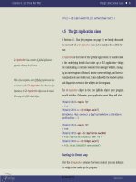
Interactive Simulation 83
A. Return to the previous simulation step by pressing the undo Simulator button.
B. In the Simulator, select the transition
38
trans dlca!dlc(1): from waitua input t320 : as shown
in Figure 4.46, the Editor displays in bold the corresponding input (T320). In the ELSE
branch, you see the output of DLCstopped, which caused the problem.
Figure 4.46 Searching for the unexpected signal bug
C. In the Editor, select Navigate > Up: the block type V76 DLC is now displayed, as in
Figure 3.12; you see that signal DLCstopped goes to process dispatch, through the signal
route DLCs.
D. In the Editor, select process dispatch and do Navigate > Down and Navigate > Next
Partition: you see that under state waitUA, the input of signal DLCstopped is missing.
4.3.3.3 Correct the bug
You will add the missing input of signal DLCstopped under state waitUA in process dispatch.
A. When the Simulator is running, the Editor prevents you from modifying the SDL model:
exit from the Simulator (answering No to the question) to enable the modification features
of the Editor. Do not exit from the Editor.
38
The firable transition trans dlca!dlc(1): from waitua input t320 is preceded by a *: it reminds you that you executed
it before the undo.
84 Validation of Communications Systems with SDL
B. In Windows (or Unix), make a copy of the file v76.pr into v76 v1.pr (but continue working
on v76.pr, which becomes version 2).
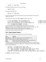
C. In process dispatch, partition part2, select the input of DLCstopped under state ready,
copy it, select the state waitUA and paste: the whole transition is inserted, as shown in
Figure 4.47.
waitUA
V76frame
(V76para)
V76para ! present
UA
V76frame(V76para)
TO DLCs(V76para
! UA ! DLCi)
ready
ELSE
-
DLCstopped
(DLCnum)
L_ReleaseInd(DLCnum)
DLCs(DLCnum):= NULL
ready
Figure 4.47 Missing input of signal DLCstopped added under state waitUA
D. In the pasted transition, don’t forget to change the nextstate -intonextstate ready,otherwise
you will be stuck in state waitUA.
E. Save the SDL model.
4.3.3.4 Simulate to check the bug correction
To check that the bug has been corrected, you will load and automatically replay the scenario
stored in Section 4.3.3.1. See Section 4.3.1 for details on restarting the Simulator.
A. In the SDL Editor, unload all files except v76.pr.
B. If the ObjectGeode Launcher is not running, in the Editor select Tools > SDL & MSC
Simulator.
C. In the ObjectGeode Launcher, Press the Build button, then if you do not get any SDL errors,
press the Execute button.
D. The Simulator starts: press on SDL Tracking and on Start MSC .
E. In the Editor, close all windows except Default tracking and ogsm4, close the Framework
view and select Window > Tile Horizontally, to obtain the screen shown in Figure 4.38.
F. In the Simulator, select File > Scenario > Load , and open retry1.scn:afterend of scenario
loading, you see 0/26 in the lower part of the Simulator, as shown in Figure 4.48: it means
that you are at Step 0, and the loaded scenario has 26 steps.
G. Press the button All located under Redo: (or press 26 times the redo
Simulator button):
when you see end of scenario execution and 26/26, it means that the scenario loaded from
the file retry1.scn has been replayed entirely
39
.
39
If the scenario does not replay until the end, check that your feeds are loaded: see Section 4.3.1.4.
Interactive Simulation 85
Figure 4.48 The current and maximum step numbers after loading the scenario
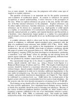
H. The bottom of the MSC generated by the Simulator looks like Figure 4.49(a): the signal
dlcstopped has been transmitted, but it is in the queue of process dispatch.
dlcstopped(0)
dlcstopped(0)
(a) (b)
Figure 4.49 MSC trace: signal dlcstopped in the process queue (a) and consumed (b)
I. To watch the input FIFO queues of the model, press the Watch button; in the Watch
creation window, press Queues: as depicted in Figure 4.50, a watch window appears, dis-
playing the contents of the queues. As expected, you can see the signal dlcstopped in the
queue of process dispatch.
first signal in the queue
signal name
signal parameter value
empty queue
Figure 4.50 Watching the input queues
J. In the Simulator, double-click the transition
trans dlca!dispatch : from_waitua_input_dlcstopped
the signal dlcstopped disappears from the watch and the MSC shows a filled arrowhead as
in
40
Figure 4.49(b).
We have returned to the initial model state, from where we can simulate other scenarios.
40
The arrow is inclined, because the actual input of dlcstopped (the arrowhead) occurred after the process stop (the X
symbol). A horizontal arrow would mean output dlcstopped, followed by input dlcstopped and then by process stop,
which is not the actual behavior.
86 Validation of Communications Systems with SDL
4.3.4 Detect nonsimulated parts
After a simulation session, the Simulator indicates
41
which parts of the SDL model have not
been simulated:
• states
• transitions
• basic blocks
42
An example of state, transition and basic block is provided in Figure 4.51.
process DLC (0, maxDLC + 1) FPAR me DLCident, originator Boolean
connected
L_DataReq
( , uData)
We do not
get the first
parameter
Iparam :=
fill_Iframe(me, uData, 15)
V76frame(I : Iparam)
VIA peer
-
L_ReleaseReq
V76frame
(DISC : (. me .))
VIA peer
waitUAdisc
V76frame (V76para)
V76para ! present
UA, DM
DLCstopped(me)
ELSE
-
V76frame (V76para)
V76para ! present
DISC
V76frame
(UA : (. me .))
VIA peer
DLCstopped
(me)
CALL CRCok
(V76para ! I !CRC)
True
L_DataInd
(me, V76para! I ! data)
False
-
ELSE
-
a state
a transition
a basic
block
I
Figure 4.51 Examples of state, transition and basic block
Then you can simulate again the SDL model until you reach 100% coverage for the states,
transitions and basic blocks. After playing all possible scenarios (which is easier using exhaustive
simulation, if the model does not have too many states), the states, transitions and basic blocks
not simulated are considered as “dead” parts: they can be removed, after careful inspection.
A. If the Simulator is already running, jump to E.
B. In the SDL Editor, unload all files except v76.pr.
C. If the ObjectGeode Launcher is not running, in the Editor select Tools > SDL & MSC
Simulator.
D. In the ObjectGeode Launcher, Press the Execute button: the Simulator starts.
41
A counter is associated to each state, each transition and each basic block: every time a state, transition or basic
block is simulated, its counter is incremented. A value of 0 means it has never been simulated.
42
In fact, basic blocks include transitions (except the implicit transition corresponding to discarding an unexpected
signal).
Interactive Simulation 87
Figure 4.52 The Simulator Hierarchy Browser
E. In the Simulator, select View > Hierarchy: the Hierarchy Browser appears, as shown in
Figure 4.52.
F. In the Hierarchy Browser, press the button Reset Coverage:this
43
sets to 0 the coverage
counters, in case you did not restart the Simulator just before this exercise.
G. In the Hierarchy Browser, select v76test and press the button+ : this displays the coverage
rates of the SDL model, as illustrated in Figure 4.53.
states coverage
transitions coverage
basic blocks coverage
Figure 4.53 The coverage rates
43
It seems that there are two minor problems in the version 4.2.2 of the Simulator: just after starting the Simulator,
without executing any transition, the start symbols of processes atob, btoa and dispatch are marked as executed
2 times instead of 0 (type cover state all), and if you press the button Reset Coverage in the Hierarchy Browser,
the coverage counters are all correctly set to 0, but the Hierarchy Browser does not display 0 concerning btoa and
dlcb!dispatch. In fact the coverage for btoa and dlcb!dispatch should not be displayed, as they are instances of the
same entities than atob and dlca!dispatch. As they concern only start transitions, which will be executed in any case,
these problems are not dangerous.
88 Validation of Communications Systems with SDL
The first number is the percentage of states simulated, the second number is the percentage
of transitions simulated and the last number is the percentage of basic blocks simulated.
H. In the Simulator, select File > Scenario > Load, and open test1.scn (see Section 4.3.2.3).
I. When you see end of scenario loading, press the button All located under Redo.
The Hierarchy Browser now displays the new values of the coverage rates, as shown in
Figure 4.54.
Figure 4.54 The coverage rates after replaying test1
We see, for example, that
• all the states in process atob, dispatch and dlc have been simulated,
• 90.9% of the transitions in process dispatch have been simulated,
• 72.4% of the basic blocks in process dispatch have been simulated.
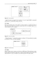
J. Select dispatch in dlca in the Hierarchy Browser and press the two buttons shown in
Figure 4.55: one displays all the transitions, the other displays only nonexecuted transitions;
you see that the only transition not simulated is from
waitua input dlcstopped.
K. In the Hierarchy Browser, select from
waitua input dlcstopped and press Locate: the Editor
opens process dispatch and selects the uncovered transition, as shown in Figure 4.56.
As we have only replayed the scenario test1.scn, it is normal for this transition to be detected
as not simulated. To simulate it, we need to replay (without resetting the coverage counters)
retry1.scn also and execute the transition trans dlca!dispatch: from
waitua input dlcstopped.
4.3.5 Validate against more scenarios
After simulation of the main scenarios described in Section 4.3.2, it is wise to play more
scenarios to check the reaction of the SDL model. Those scenarios can be:
Interactive Simulation 89
Figure 4.55 The transition not simulated in dispatch
waitUA
V76frame
(V76para)
V76para ! present
UA
V76frame(V76para)
TO DLCs(V76para
! UA ! DLCi)
ready
ELSE
-
DLCstopped
(
DLCnum)
L_ReleaseInd(DLCnum)
DLCs(DLCnum):= NULL
ready
Figure 4.56 The transition not simulated is automatically located
• more complex: for example, two simultaneous connections,
• beyond limits: for example, creation of more connections than allowed.
4.3.5.1 Simulate two simultaneous connections
You will simulate to check that the SDL model can handle two connections in parallel.
A. If the Simulator is already running, jump to E.
B. In the SDL Editor, unload all files except v76.pr.
C. If the ObjectGeode Launcher is not running, in the Editor select Tools > SDL & MSC
Simulator.
D. In the ObjectGeode Launcher, press the Build button, then if you do not get any SDL errors,
press the Execute button.
90 Validation of Communications Systems with SDL
E. The Simulator starts: press on SDL Tracking and on Start MSC .
F. In the Editor, close the Framework view and select Window > Tile Horizontally, to obtain
the screen shown in Figure 4.38.
G. Load and replay the scenario cnx1.scn, as indicated for retry1.scn in Section 4.3.3.4: now
one instance of process DLC exists on each side of the system.
Now establish one more connection:
H. Execute the transition dlca!dispatch: from
ready input l estabreq with l estabreq(1) from
env
dlcasu (double-click it in the Simulator list, as shown in Figure 4.57). You see in the
MSC trace that a new instance of process DLC is created, numbered 2.
Figure 4.57 The transition to fire
I. In the same way, execute the following transitions:
dlca!dlc(2) : start
atob(1) : from_ready_input_v76frame
atob(1) : decision_lose_the_frame(
No
)
dlcb!dispatch : from_ready_input_v76frame
dlcb!dispatch : from_waitestabresp_input_l_estabresp with
l_estabresp from env_dlcbsu
dlcb!dlc(2) : start
Interactive Simulation 91
btoa(1) : from_ready_input_v76frame
btoa(1) : decision_lose_the_frame(
No
)
dlca!dispatch : from_waitua_input_v76frame
dlca!dlc(2) : from_waitua_input_v76frame
The new connection has been established between sides A and B.
J. To check that all four instances of process DLC exist and are in state connected,enterin
the Simulator:
print dlc!state
The Simulator displays:
dlcb!dlc(1) ! state = connected
dlcb!dlc(2) ! state = connected
dlca!dlc(1) ! state = connected
dlca!dlc(2) ! state = connected
K. To test that the new connection
44
works, let’s transfer data through it; execute the following
transitions:
dlca!dispatch : from_ready_input_l_datareq with l_datareq(1,
39) from env_dlcasu
dlca!dlc(2) : from_connected_input_l_datareq
atob(1) : from_ready_input_v76frame
atob(1) : decision_lose_the_frame(
No
)
dlcb!dispatch : from_ready_input_v76frame
dlcb!dlc(2) : from_connected_input_v76frame
The generated MSC, represented at blocks level in Figure 4.58, shows that block DLCb
transmitted signal L
DataInd(1, 39) to the environment (representing Service User B): the
data 39 has been successfully transferred from A to B through DLC 1.
L. Save the Simulator scenario: in the Simulator, select File > Scenario > Save As,entercnx2
and press save.
M. To save the current MSC into the file cnx2.msc, enter the following command into the Sim-
ulator:
msc cnx2
4.3.5.2 Simulate an attempt to create too many connections
You will simulate to see what happens if you try to create more connections than allowed. The
maximum number of parallel connections in our model is maxDLC + 1 = 2. Figure 3.12 shows
that this number corresponds to the maximum number of instances or process DLC ,whichis
equal to the size of the array DLCs, declared in Figure 3.14.
44
The DLC number (of type DLCident) of the new connection is 1, and the corresponding instance number of process
DLC (given by the Simulator) is 2.
92 Validation of Communications Systems with SDL
cnx2
/* Establishment of DLC number 0: */
/* Establishment of DLC number 1: */
/* Transfer of data 39 through DLC number 1: */
l_estabreq( 0 )
v76frame( sabme : (. 0 .) )
v76frame( ua : (. 0 .) )
l_estabconf( 0 )
l_estabreq( 1 )
v76frame( sabme : (. 1 .) )
v76frame( ua : (. 1 .) )
l_estabconf( 1 )
l_datareq( 1,39 )
v76frame( i : (. 1,39,15 .) )
v76frame( sabme : (. 0 .) )
v76frame( ua : (. 0 .) )
v76frame( sabme : (. 1 .) )
v76frame( ua : (. 1 .) )
v76frame( i : (. 1,39,15 .) )
l_estabind( 0 )
l_estabresp
l_estabind( 1 )
l_estabresp
l_dataind( 1,39 )
DLCa
BLOCK /
v76test
/dlca
dataLink
BLOCK /
v76test/
datalink
DLCb
BLOCK /
v76test
/dlcb
Figure 4.58 Twoconnections0and1inparallel
A. If you exited the tools since Section 4.3.5.1, launch the Simulator and replay the scenario
cnx2.scn: two instances of process DLC exist on each side of the system, the maximum
is reached.
B. Execute the transition dlca!dispatch: from
ready input l estabreq with l estabreq(0) from
env
dlcasu. You see in the MSC trace that the system answers with an L RelelaseInd(0):
it means that no more connection can be established.
But if you look at the SDL trace (or enter print state), you discover that process dispatch
is stuck in state waitUA: this is a modeling bug. Also, transitions are missing in the list of
firable transitions.
You will correct process dispatch to go to state ready instead of state waitUA after trans-
mitting L
RelelaseInd.
C. Exit from the Simulator (answering No to the question) to enable the modification features
of the Editor. Do not exit from the Editor.
D. In Windows (or Unix), make a copy of the file v76.pr into v76
v2.pr.
E. In process dispatch, partition part2, select the output of L
RelelaseInd under the ELSE
branch of the decision and click on the nextstate palette symbol; enter – in the newly
created symbol, as shown in Figure 4.59.
F. Save the SDL model.
Interactive Simulation 93
L_EstabReq
(DLCnum)
DLCs
(DLCnum)
NULL
DLC
(DLCnum, True)
DLCnumnot
used, we
create
an instance of
process DLC
DLCs(DLCnum)
:= OFFSPRING
We store into the
table the PID of
the new
instance
ELSE
L_ReleaseInd
(DLCnum)
-
waitUA
Figure 4.59 After the bug correction
G. Simulate again to check that the bug has disappeared: replay the scenario cnx2.scn,and
execute the transition dlca!dispatch: from
ready input l estabreq with l estabreq(0) from
env
dlcasu:processdispatch now stays in state ready.
4.3.6 Write a script for automatic validation
In an actual project, to test a more complex SDL model, you would produce, for example,
40 simulation scenarios. After a change in the SDL model, you must check that it still works
correctly (nonregression) : the Simulator command language enables you to write a script to
automatically replay the 40 scenarios (stored in .scn files) and write the test results into a file.
By just looking if the file contains TEST FAILED or TEST PASSED, you will know if the 40
scenarios replayed correctly or not.
Here is a Simulator script to replay three of our scenarios:
1 This geodesim script replays 3 scenarios to test V.76
2 and writes the results into test_res1.wri
3
4 define test_failed False
5
6echo
7echo
Execution of script1.wri:
|| test_res1.wri
8echo
||| test_res1.wri
9
10 init return to step 0
11 source test1.scn replays test1.scn
12 now check that test1.scn executed till the end (step 41)
13 and that both DLCs arrays contain Null:
14 if (step=41) and (dlca!dispatch ! dlcs = (. Null .)) and
\
15 (dlcb!dispatch ! dlcs = (. Null .)) ;
16 echo
Replay test1.scn OK
||| test_res1.wri;
94 Validation of Communications Systems with SDL
17 else ;
18 define test_failed True;
19 echo
Error found in test1.scn
||| test_res1.wri;
20 fi
21
22 init return to step 0
23 source cnx2.scn
24 now check that cnx2.scn executed till the end (step 32)
25 and that the 4 inst. of process DLC are in state connected:
26 if (step=32) and (dlca!dlc(1)!state = connected) and
\
27 (dlca!dlc(2)!state = connected) and \
28 (dlcb!dlc(1)!state = connected) and \
29 (dlcb!dlc(2)!state = connected) ;
30 echo
Replay cnx2.scn OK
||| test_res1.wri;
31 else ;
32 define test_failed True;
33 echo
Error found in cnx2.scn
||| test_res1.wri;
34 fi
35
36 init return to step 0
37 source retry1.scn
38 now check that retry1.scn executed till the end (step 26) and
39 that queue of process dispatch contains signal DLCstopped:
40 if (step=26) and (dlca!dispatch ! queue(1)!name = DLCstopped) ;
41 echo
Replay retry1.scn OK
||| test_res1.wri;
42 else ;
43 define test_failed True;
44 echo
Error found in retry1.scn
||| test_res1.wri;
45 fi
46
47 echo
||| test_res1.wri
48 if $test_failed ;
49 echo
** TEST FAILED; see test_res1.wri ***
||| test_res1.wri
51 else ; echo
TEST PASSED
||| test_res1.wri
52 fi
Here are a few explanations on the script:
• The character \ means continue on next line.
• Line 4:
define test failed False: defines the value test failed and sets it to False.
• Line 7:
echo
Execution of script1.wri:
|| test res1.wri: writes ‘Execution of
script1.wri:’ in the simulator trace and into the file test
res1.wri.
• Line 11:
source test1.scn: same as loading scenario test1.scn and redoing all.
• Line 14:
if (step=41): step contains the current step number; we know that the scenario
in test1.scn has 41 Steps; if after replay the step number is lower than 41, it means that the
scenario did not run completely.
Interactive Simulation 95
• Line 14: DLCa!dispatch!DLCs = (. Null.): DLCs is an array declared in process
dispatch; after the scenario replay, we know that all its elements must contain Null.
• Line 16: if the conditions above are true, we write ‘Replay test1.scn OK’ into the file
test
res1.wri, otherwise we write ‘Error found in test1.scn’ and we set test failed to True.
• Then we repeat a similar code for scenarios cnx2.scn (line 23) and retry1.scn (line 37), with
different conditions.
• Line 48: finally, if test
failed contains True, we write TEST FAILED,otherwiseTEST PASSED.
Once you have typed the script into the file script1.wri
45
(do not type the line numbers),
execute it:
A. Launch the Simulator.
B. Click the Simulator button Traces: Off to see only the script traces.
C. Enter source script1.wri in the Simulator. If the model (and the script!) is correct, you see
> source script1.wri
Execution of script1.wri:
scenario in initial state
Replay test1.scn OK
scenario in initial state
Replay cnx2.scn OK
scenario in initial state
Replay retry1.scn OK
TEST PASSED
The file test res1.wri contains the same results, informing you of which scenario(s) failed.
By just reading the last line, you are sure that all the scenarios passed.
If you want to generate the MSC trace and store it into the file test5.msc after replaying a
scenario, you can add the following command into the script:
msc test5
You will learn in Chapter 5 how to check that your SDL model behavior complies with an
MSC. This will be even more powerful to test automatically an SDL model: for example, we will
be able to check the value of a parameter in a signal transmitted, which is not performed here.
4.3.7 Other Simulator features: watch, trace, filter etc.
This section describes features of the Simulator not absolutely essential to validate an SDL
model, but which can be very helpful and save a lot of time on an actual system validation.
45
The file extension .wri ensures opening the file with WordPad just by double-click, if you are running Microsoft
Windows
TM
.
96 Validation of Communications Systems with SDL
4.3.7.1 Aliases
To shorten textual commands, you can create aliases, a kind of macros. Alias definitions are
generally stored in the file geodesm.startup (see Section 4.3.7.2) to be executed automatically.
Here are some examples of aliases you could write:
alias h
history
alias p
Basic blocks (paths) never executed:
alias bb0
cover bblocks all 0:0
Then, you have only to enter h instead of history, bb0 instead of cover bblocks all 0:0,and
so on.
Also, aliases can have parameters; for example, to print the state of instance $2 of process
DLC in block DLC $1:
> alias p_dlc
print dlc$1!dlc($2)!state
> p_dlc a 1
dlca!dlc(1) ! state = waitua
4.3.7.2 Automatic scripts execution at simulator startup
When the Simulator starts, three scripts are automatically executed, if they exist, as shown in
Figure 4.60:
geodesm.startup
SDL
Simulator
geodesm.startup
v76.startup
1. For all users
2. For you
3. For model v76.pr
Figure 4.60 The three Simulator startup files
1. The file geodesm.startup common to all the Simulator users, rarely used, located in the
installation directory of ObjectGeode.
2. The file located for Unix in your home directory, $HOME/geodesm.startup, or for Windows
NT in your profile, C:\winnt\profiles\your
name\ObjectGeode\geodesm.startup.
3. The file name.startup,wherename is the name of the file containing the SDL system. For
example, if your model is stored in v76.pr, the startup file must be named v76.startup ,
located in the current directory
46
. It contains commands specific to a certain model, such
as firing the start transitions and loading feed commands.
46
In Unix, beware of navigating (using cd) to the directory containing the SDL model before launching ObjectGeode.
Otherwise, the Simulator will run in the wrong directory: files will not be generated where you expect them and the
model startup file will not be found.
Interactive Simulation 97
A fourth script is executed if the Simulator is invoked with the -startup option. For example,
geodesim v76 -startup my_file.wri
Example of script geodesm.startup to put in your home directory (Unix) or in your profile
directory (Windows NT):
Abbreviated commands :
alias h
history
alias p
alias u
undo
alias r
redo
alias t
trace
alias ve
verify
alias vo
verify options
Coverage rates:
alias cov
print state_cover_rate(system); \
print trans_cover_rate(system); \
print bb_cover_rate(system)
States never executed:
alias cs0
cover state all 0:0
Transitions never executed:
alias ct0
cover trans all 0:0
Basic blocks (paths) never executed:
alias bb0
cover bblocks all 0:0
More compact generated MSCs: (does not work on PC)
define msc_xspace
140
define msc_yspace
20
To store only 2 .scn files of each kind (for verify),
(default is 10):
stop limit 2
deadlock limit 2
exception limit 2
error limit all 2
success limit all 2
define scc_sink_limit
2
To display states number of every process and queue
after exhaustive simulation:
define verify_stats
true
98 Validation of Communications Systems with SDL
To be able to time-out timers more easily:
define loose_time
true
List the alias definitions:
alias
4.3.7.3 Running the Simulator without its graphical interface
To perform automatic tasks such as automatic replay of scenarios, the Simulator can be launched
without its graphical interface; this is called batch mode. To run in batch mode, after the build
(textual command: gsmcomp v76), type the following command (suppose the SDL model is in
the file v76.pr) in a DOS or Unix shell (containing v76.sim):
F:\DONNEES\V76> geodesim -b v76
SDL Simulator V4.2.2 Copyright 1989-2001 by Telelogic AB.
1 : atob(1) : start
2 : btoa(1) : start
3 : dlca!dispatch : start
4 : dlcb!dispatch : start
The Simulator displays the list of ready transitions. To fire a transition, just enter its number:
>2
step = 1
trans btoa(1) : start
+ START ;
+ NEXTSTATE ready;
1 : atob(1) : start
2 : dlca!dispatch : start
3 : dlcb!dispatch : start
>
Then you can enter any Simulator textual command:
> print now
now = 0.0
The commands to execute can be inserted in the file v76.startup, automatically played when
the Simulator starts. For example, the automatic simulation script script1.wri described in
Section 4.3.6 can be executed automatically if the file v76.startup contains
source script1.wri
quit
4.3.7.4 Commands history
To reenter a Simulator command like in a Unix shell, type history, a nd the 10 last executed
commands will be displayed:
> history
Interactive Simulation 99
1 : let x = 34
2 : print state
3 : alias f
feed
4 : print now
5 : print trans_cover_rate(v76test)
6 : print dlcs
7 : trace
8 : redo 6
9 : mode depth
10 : history
Then you can reexecute a command by typing !n,wheren is the number in the list. For
example, !4 reexecutes print now, and !! reexecutes the last command.
4.3.7.5 Examining the SDL model: print
The print command displays the contents of any SDL or simulation element. Here are some
examples, to type in the Simulator command line, shown in Figure 4.44.
To display the current time:
> print now
now = 48.0
To display the synonym maxDLC :
> print maxDLC
maxdlc = 1
To display all the array variables named DLCs:
> print DLCs
dlcb!dispatch ! dlcs = in DLCb
0 = null
1 = null
dlca!dispatch ! dlcs = in DLCa
0 = dlca!dlc(2)
1 = null
To display only the variable DLCs contained in process dispatch in block DLCa:
> print dlca!dispatch ! dlcs
dlca!dispatch ! dlcs =
0 = dlca!dlc(2)
1 = null
To display the input queue contents of each process instance:
> print queue
btoa(1) ! queue = {} means queue empty
atob(1) ! queue = {}
100 Validation of Communications Systems with SDL
process dlcb!dlc not created or stopped
process dlca!dlc not created or stopped
dlcb!dispatch ! queue = {}
dlca!dispatch ! queue =
1 = first queue element
sender = dlca!dlc(1) who sent it
name = dlcstopped signal name
dlcstopped =
p1 = 0 first signal parameter
To display the current state of each process instance:
> print state
btoa(1) ! state = ready
atob(1) ! state = ready
process dlcb!dlc not created or stopped
process dlca!dlc not created or stopped
dlcb!dispatch ! state = ready
dlca!dispatch ! state = waitua
To display all the model contents (current global state):
> print all
atob(1) =
substate = none
state = ready
sender = dlca!dlc(1)
parent = null
etc.
To test if process dispatch in block DLCa is in state waitUA and Now < 10:
> print (DLCa!dispatch!state=waitUA) and (Now < 10)
(dlca!dispatch ! state = waitua) and (now < 10.0) = false
To call the operator fill Iframe to test it:
> print fill_Iframe(1, 39, 15)
fill_iframe(1, 39, 15) =
dlci = 1
data = 39
crc=15
To call the ObjectGeode-specific predefined SDL operator hexadecimal to convert a number to
hexadecimal:
> p hexadecimal(15)
hexadecimal(15) = 0xf
Interactive Simulation 101
To call the ObjectGeode-specific predefined SDL operator integer to convert a hexadeci-
mal number:
> p integer(0xF)
integer(0xf) = 15
4.3.7.6 Examining the SDL model: watch windows
The watch command opens one or more watch windows displaying the contents of any SDL
or simulation element, refreshed every time its value changes.
The button Watch allows to create predefined watch windows to display the contents of all
the process input queues, process (and procedure or services) states, and so on.
To watch a specific element, you must select Edit > Create watch, then right-click to open
a shortcut menu, where the choice Add Item prompts you to enter the name of the entity you
want to put in the watch. The syntax for names you enter here is the same as that for the textual
command print. For example, you can enter a variable name, such as DLCs, to watch all the
occurrences of variable DLCs, as shown in Figure 4.61.
Figure 4.61 A watch window
As each DLCs is an array with two elements, the watch shows the content of each element.
To get the same watch windows the next time you launch the Simulator, you can select
File > Watches > Save As and enter a file name such as test1.watch. Then you can add the
command source test1.watch into your model startup file (example: v76.startup)tocreatethe
watch windows automatically.
4.3.7.7 Examining the SDL model: trace
The trace command displays in the textual trace the content of any SDL or simulation element,
after every simulation step. It also writes this content in the MSC trace, every time its value
changes. The syntax for names you enter here is the same as that for the textual command print.
For example, to trace the value of the variable N320cnt in block DLCa, type in the Simulator
command line
trace dlca!dlc(1) ! n320cnt
The effect in the MSC trace is depicted in Figure 4.45. Trace is handy when searching the
origin of a hard to find bug: you can trace the state of each process instance, of variables, of
process queues, and so on.
102 Validation of Communications Systems with SDL
4.3.7.8 Modifying the SDL model
Two commands allow you to modify during simulation the content of an element in the SDL
model: the let textual command, and the change value graphical command, available in the
watch windows.
The let command accepts the same arguments as the print command (except that you must
specify the path if more than one occurrence of the element exists in the SDL model). For
example, to enter 2 in the variable N320cnt in block DLCa, type in the Simulator command line:
let DLCa!DLC(1)!N320cnt = 2
To change easily the value of complex structures such as arrays, struct or ASN.1 val-
ues the Simulator provides the change value command in the shortcut menu available in
watch windows.
For example, to change the value of the second element in the array DLCs declared in process
dispatch contained in block DLCb,
A. Create the watch as in Figure 4.62: select Edit > Create watch, choose Add Item in the
shortcut menu and type DLCs.
B. Select the line corresponding to the element to change, as in Figure 4.62a.
C. Right-click to open the shortcut menu, and select Change Value: the Change Value win-
dow appears.
(a) (b)
Figure 4.62 (a) Variables DLCs in a watch and (b) the Change Value window
Interactive Simulation 103
D. In the field New Value, e nter the desired value (such as DLCa! DLC (1)!self, the Pid of the
instance 1 of process DLC contained in block DLCa) and press Apply.
The array DLCs in DLCb is changed; note that the SDL model is now in an inconsistent
state and is no longer supposed to work.
4.3.7.9 Removing some behaviors: filters
The Simulator filter command allows you to freeze some parts of the SDL model. For example,
to block the answer ‘Yes’ in the informal decision represented in Figure 4.63, type the following
command in the Simulator:
filter trans atob(1):decision_lose_the_frame(
Yes
)
ready
V76frame(V76par)
'Lose the frame ?'
'No'
V76frame (V76par)
VIA gOut
'Yes'
-
'Lose the frame ?'
Figure 4.63 The informal decision in process type topeer
When you reach the decision, the Firable Transition area of the Simulator will only contain
the transition corresponding to ‘No’ :
trans atob(1) : decision_lose_the_frame(
No
)
instead of:
trans atob(1) : decision_lose_the_frame(
No
)
trans atob(1) : decision_lose_the_frame(
yes
)
You can add several filter conditions and manage them with Edit > Filter Conditions.To
enter a filter condition with this command, do not type the keyword filter in front of the
condition.
Filter conditions are also active during random and exhaustive simulation, where they are very
handy to guide the simulation automatically. In such modes, the transitions fired are selected
by the Simulator, not by you; thus, you must filter a certain transition if you do not want the
Simulator to fire it.
104 Validation of Communications Systems with SDL
We have seen how to filter a certain transition (filter trans ), but the argument of the filter
command can also be an expression or an event. Here are some examples.
To prevent from firing any transition leading to variable n320cnt > 2 (simulation will only
be possible for values 0, 1 and 2):
filter n320cnt > 2
To prevent any output of signal L EstabInd:
filter output L_EstabInd
To limit to 2 signals the content of the input queue of instance 1 of process DLC in block
DLCa (the part is
active is not necessary for a process instance that always exists, such as
dispatch(1)):
filter is_active(DLCa!DLC(1)) and \
length(DLCa!DLC(1)!queue) > 2
To prevent instance 1 of process DLC in block DLCa from reaching the state connected:
filter DLCa!DLC(1)!state = connected
To block all the transitions contained in the block DLCa:
filter trans DLCa
4.3.7.10 Undo and redo Simulator commands
Undo enables you to go back to any previous simulation step; then you can use redo to replay
the previously undone steps. Redo is also used to replay a loaded scenario.
Two buttons in the Simulator perform undo and redo of one step at a time:
and .To
undo or redo a larger number of steps, you can use the textual commands undo and redo.For
example, if you are at Step 27, you can type:
undo 16 returns to step 27 - 16 = 11
redo 8 returns to step 11 + 8 = 19
4.3.7.11 Declaring simulation variables
Simulation variables can be declared in the Simulator:
• work variables: using the command dcl, like in SDL
• environment variables: using the command define
Example of work variable:
dcl x integer
let x = 45
print x
letx=x+1
Interactive Simulation 105
Example of environment variable (extract from the script in Section 4.3.6):
define test_failed False
etc.
if $test_failed; echo
TEST FAILED
else; echo
TEST PASSED
;fi
4.3.7.12 Two important Simulator options
The Simulator behavior can be configured thanks to several options; to see all the options, enter
the textual command define. For the main options, the Edit > Configuration command opens
the Simulator configuration window represented in Figure 4.64.
define reasonable_feed 'false'
define loose_time 'true'
Figure 4.64 The Simulator configuration window
We explain two important options here: reasonable environment and loose time progression.
If you want to set these options automatically, enter the appropriate define command, indi-
cated in Figure 4.64, in one of your Simulator startup files.
Reasonable environment allows the input of an external signal (coming from the feed com-
mand) only if the SDL model is in a ‘quiet’ state. Quiet means that all the input queues in the
SDL model are empty and all the start transitions have been executed.
For example, if you start the simulation of V.76 and click on init
, after starting process
dispatch you get nine firable transitions with reasonable environment off, instead of three
transitions if you turn it on, as illustrated in Figure 4.65. When on, the Simulator wants you to
first finish starting all the process instances before enabling the input of external signals.
In practice, the simulation is simpler when reasonable environment is on, because there are
generally fewer transitions to select in the list. But in certain models, some behaviors can
only be simulated when reasonable environment is off (for example, here you cannot send any
L
EstabReq to the model before starting the 4 process instances).
106 Validation of Communications Systems with SDL
(a) (b)
Figure 4.65 Reasonable environment off (a) and on (b)
If loose time progression is off, the Simulator will not allow any time progression while the
simulation is not ‘blocked’. We remind you that in the Simulator, the execution duration of
the SDL instructions is supposed to be zero. If you simulate the model shown in Figure 4.66,
once you have executed the start transition, timer TIMER1 is started, and process proc1 is in
state st1.
process proc1
TIMER TIMER1:= 15.0;
DCL x Integer;
SET (TIMER1)
st1
st1
NONE
x:= 3
st1
system L_time
b1
block b1
proc1
Figure 4.66 Example with timer
If loose time progression is off, as shown in Figure 4.67(a), the Simulator will only propose
that you execute forever the transition input none. Because this transition does not make the
time progress (it does not contain any timers), the SDL time, Now, is stuck to zero. The only
way to get the time progression transition time(15) as in Figure 4.67(b) is to set loose time
progression to on.
In practice, it is easier to set loose time progression to on: as soon as you set a timer, you
are allowed to time it out. Otherwise you might have to execute first some other transitions, or
in the worst cases, it might never time-out, as in the example above.
Interactive Simulation 107
(a) (b)
Figure 4.67 Loose time progression off (a) and on (b)
4.3.7.13 Automated generation of feed
To generate automatically the feed commands to transmit external signals to an SDL model,
type in the Simulator (feature not available in early versions):
feed ?
For example, in the V.76 SDL model, the Simulator would answer:
Feeds skeleton for channel dlcbsu
feed dlcbsu l_estabreq(?)
feed dlcbsu l_estabresp()
feed dlcbsu l_setparmreq()
feed dlcbsu l_setparmresp()
feed dlcbsu l_releasereq(?)
feed dlcbsu l_datareq(?,?)
Feeds skeleton for channel dlcasu
feed dlcasu l_estabreq(?)
feed dlcasu l_estabresp()
feed dlcasu l_setparmreq()
feed dlcasu l_setparmresp()
feed dlcasu l_releasereq(?)
feed dlcasu l_datareq(?,?)
Then you can copy the feed skeletons and paste them into a file executed at startup. The
character ? in the feed skeletons means the default value. For example, for Integer, the default
value is 0.