biến tần delta phần 2 pptx
Bạn đang xem bản rút gọn của tài liệu. Xem và tải ngay bản đầy đủ của tài liệu tại đây (484.29 KB, 20 trang )
Chapter 1 Introduction|
1-10 Revision June 2007, 0ELE, V1.00
NOTE
Frame A: VFD002EL11A/21A/23A, VFD004EL11A/21A/23A/43A, VFD007EL21A/23A/43A,
VFD015EL23A/43A
Frame B: VFD007EL11A, VFD015EL21A, VFD022EL21A/23A/43A, VFD037EL23A/43A
Revision June 2007, 0ELE, V1.00 2-1
Chapter 2 Installation and Wiring
After removing the front cover, check if the power and control terminals are clear. Be sure to observe
the following precautions when wiring.
General Wiring Information
Applicable Codes
All VFD-EL series are Underwriters Laboratories, Inc. (UL) and Canadian Underwriters
Laboratories (cUL) listed, and therefore comply with the requirements of the National
Electrical Code (NEC) and the Canadian Electrical Code (CEC).
Installation intended to meet the UL and cUL requirements must follow the instructions
provided in “Wiring Notes” as a minimum standard. Follow all local codes that exceed UL
and cUL requirements. Refer to the technical data label affixed to the AC motor drive and
the motor nameplate for electrical data.
The "Line Fuse Specification" in Appendix B, lists the recommended fuse part number for
each VFD-EL Series part number. These fuses (or equivalent) must be used on all
installations where compliance with U.L. standards is a required.
CAUTION!
1. Make sure that power is only applied to the R/L1, S/L2, T/L3 terminals. Failure to comply may
result in damage to the equipment. The voltage and current should lie within the range as
indicated on the nameplate.
2. All the units must be grounded directly to a common ground terminal to prevent lightning strike
or electric shock.
3. Please make sure to fasten the screw of the main circuit terminals to prevent sparks which is
made by the loose screws due to vibration.
4. Check following items after finishing the wiring:
A. Are all connections correct?
B. No loose wires?
C. No short-circuits between terminals or to ground?
Chapter 2 Installation and Wiring|
2-2 Revision June 2007, 0ELE, V1.00
DANGER!
1. A charge may still remain in the DC bus capacitors with hazardous voltages even if the power
has been turned off. To prevent personal injury, please ensure that the power is turned off and
wait ten minutes for the capacitors to discharge to safe voltage levels before opening the AC
motor drive.
2. Only qualified personnel familiar with AC motor drives is allowed to perform installation, wiring
and commissioning.
3. Make sure that the power is off before doing any wiring to prevent electric shock.
2.1 Wiring
Users must connect wires according to the circuit diagrams on the following pages. Do not plug a
modem or telephone line to the RS-485 communication port or permanent damage may result.
Terminals 1 & 2 are the power supply for the optional copy keypad only and should not be used for
RS-485 communication.
Chapter 2 Installation and Wiring|
Revision June 2007, 0ELE, V1.00 2-3
AVI
A
CI/AVI
ACM
+10V
5K
3
2
1
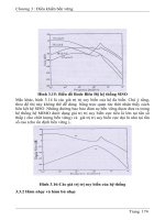
Figure 1 for models of VFD-EL Series
VFD002EL11A/21A, VFD004EL11A/21A, VFD007EL11A/21A, VFD015EL21A, VFD022EL21A
Power supply
+10V 3mA
Master Frequency
0 to 10V 47K
Analog Signal Common
E
Main circuit (power) terminals
Control circuit terminals
Shielded leads & Cable
E
R(L1)
S(L2)
Fuse/NFB(None Fuse Breaker)
SA
OFF
ON
MC
MC
RB
RC
Recommended Circuit
when power supply
is turned OFF by a
fault output
R(L1)
S(L2)
E
Analog Multi-function Output
Terminal
factory setting: Analog freq.
/ current meter
0~10VDC/2mA
U(T1)
V(T2)
W(T3)
IM
3~
A
FM
A
CM
RA
RB
RC
Motor
Analog Signal common
E
E
MI1
MI2
MI3
MI4
MI6
MI5
DCM
+24V
FWD/Stop
REV/Stop
Multi-step 1
Multi-step 2
Multi-step 3
Multi-step 4
Digital Signal Common
Factory
setting
AVI
ACI
Factory setting:
AVI Mode
-
RS-485
Serial interface
1: Reserved
2: EV
5: SG+
6: Reserved
7: Reserved
8: Reserved
3: GND
4: SG-
8
1
Sw1
NPN
PNP
Factory setting:
NPN Mode
Please refer to Figure 3
for wiring of NPN
mode and PNP
mode.
BUE
braking unit
(optional)
BR
braking resistor
(optional)
Multi-function contact output
240Vac 2.5A Max.
120Vac 5A Max.
28Vdc 5AMax.
Factory setting is
malfunction indication
Factory setting: output frequency
4-20mA/0-10V
Sw2
Chapter 2 Installation and Wiring|
2-4 Revision June 2007, 0ELE, V1.00
AVI
A
CI/AVI
ACM
+10V
5K
3
2
1
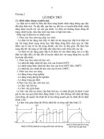
Figure 2 for models of VFD-EL Series
V
FD002EL23A, VFD004EL23A/43A, VFD007EL23A/43A, VFD015EL23A/43A,
VFD022EL23A/43A, VFD037EL23A/43A
Power supply
+10V 3mA
Master Frequency
0 to 10V 47K
Analog Signal Common
E
Main circuit (power) terminals
Control circuit terminals
Shielded leads & Cable
E
R(L1)
S(L2)
Fuse/NFB(None Fuse Breaker)
SA
OFF
ON
MC
MC
RB
RC
Recommended Circuit
when power supply
is turned OFF by a
fault output
R(L1)
S(L2)
E
Analog Multi-function Output
Terminal
factory setting: Analog freq.
/ current meter
0~10VDC/2mA
U(T1)
V(T2)
W(T3)
IM
3~
A
FM
A
CM
RA
RB
RC
Motor
Analog Signal common
E
E
MI1
MI2
MI3
MI4
MI6
MI5
DCM
+24V
FWD/Stop
REV/Stop
Multi-step 1
Multi-step 2
Multi-step 3
Multi-step 4
Digital Signal Common
Factory
setting
AVI
ACI
Factory setting:
AVI Mode
-
RS-485
Serial interface
1: Reserved
2: EV
5: SG+
6: Reserved
7: Reserved
8: Reserved
3: GND
4: SG-
8
1
NPN
PNP
Factory setting:
NPN Mode
Please refer to Figure 3
for wiring of NPN
mode and PNP
mode.
BUE
braking unit
(optional)
BR
braking resistor
(optional)
Multi-function contact output
240Vac 2.5A Max.
120Vac 5A Max.
28Vdc 5AMax.
Factory setting is
malfunction indication
Factory setting: output frequency
4-20mA/0-10V
T(L3)
T(L3)
Sw1
Sw2
Chapter 2 Installation and Wiring|
Revision June 2007, 0ELE, V1.00 2-5
Figure 3 Wiring for NPN mode and PNP mode
A. NPN mode without external power
Factory
setting
NPN
PNP
B. NPN mode with external power
Factory
setting
NPN
PNP
24
Vdc
-
+
C. PNP mode without external power
Sw1
Factory
setting
NPN
PNP
Chapter 2 Installation and Wiring|
2-6 Revision June 2007, 0ELE, V1.00
D. PNP mode with external power
Sw1
Factory
setting
NPN
PNP
24
Vdc
-
+
CAUTION!
1. The wiring of main circuit and control circuit should be separated to prevent erroneous actions.
2. Please use shield wire for the control wiring and not to expose the peeled-off net in front of the
terminal.
3. Please use the shield wire or tube for the power wiring and ground the two ends of the shield
wire or tube.
4. Damaged insulation of wiring may cause personal injury or damage to circuits/equipment if it
comes in contact with high voltage.
5. The AC motor drive, motor and wiring may cause interference. To prevent the equipment
damage, please take care of the erroneous actions of the surrounding sensors and the
equipment.
6. When the AC drive output terminals U/T1, V/T2, and W/T3 are connected to the motor terminals
U/T1, V/T2, and W/T3, respectively. To permanently reverse the direction of motor rotation,
switch over any of the two motor leads.
7. With long motor cables, high capacitive switching current peaks can cause over-current, high
leakage current or lower current readout accuracy. To prevent this, the motor cable should be
less than 20m for 3.7kW models and below. And the cable should be less than 50m for 5.5kW
models and above. For longer motor cables use an AC output reactor.
8. The AC motor drive, electric welding machine and the greater horsepower motor should be
grounded separately.
9. Use ground leads that comply with local regulations and keep them as short as possible.
10. No braking resistor is built in the VFD-EL series, it can install braking resistor for those
occasions that use higher load inertia or frequent start/stop. Refer to Appendix B for details.
11. Multiple VFD-EL units can be installed in one location. All the units should be grounded directly
to a common ground terminal, as shown in the figure below. Ensure there are no ground
loops.
Chapter 2 Installation and Wiring|
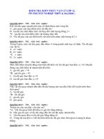
Revision June 2007, 0ELE, V1.00 2-7
Excellent
Good
Not allowed
Chapter 2 Installation and Wiring|
2-8 Revision June 2007, 0ELE, V1.00
2.2 External Wiring
Motor
Output AC
Line Reactor
Power Supply
Magnetic
contactor
Input AC
Line Reactor
EMI Filter
R/L1 S/L2
T/L3
U/T1 V/T2
W/T3
+
Zero-phase
Reactor
Zero-phase
Reactor
FUSE/NFB
-
BR
BUE
Braking
resistor
Braking unit
Items Explanations
Power
supply
Please follow the specific power
supply requirements shown in
Appendix A.
Fuse/NFB
(Optional)
There may be an inrush current
during power up. Please check the
chart of Appendix B and select the
correct fuse with rated current. Use of
an NFB is optional.
Magnetic
contactor
(Optional)
Please do not use a Magnetic
contactor as the I/O switch of the AC
motor drive, as it will reduce the
operating life cycle of the AC drive.
Input AC
Line Reactor
(Optional)
Used to improve the input power
factor, to reduce harmonics and
provide protection from AC line
disturbances.
(surges, switching
spikes, short interruptions, etc.). AC
line reactor should be installed when
the power supply capacity is 500kVA
or more and exceeds 6 times the
inverter capacity, or the mains wiring
distance
≤
10m.
Zero-phase
Reactor
(Ferrite Core
Common
Choke)
(Optional)
Zero phase reactors are used to
reduce radio noise especially when
audio equipment is installed near the
inverter. Effective for noise reduction
on both the input and output sides.
Attenuation quality is good for a wide
range from AM band to 10MHz.
Appendix B specifies the zero phase
reactor. (RF220X00A)
EMI filter
It is used to reduce electromagnetic
interference. All 230V and 460V
models are built-in EMI filter.
Braking
Resistor and
Braking Unit
(Optional)
Used to reduce the deceleration time
of the motor. Please refer to the chart
in Appendix B for specific Braking
Resistors.
Output AC
Line Reactor
(Optional)
Motor surge voltage amplitude
depends on motor cable length. For
applications with long motor cable
(>20m), it is necessary to install a
reactor at the inverter out
p
ut side.
Chapter 2 Installation and Wiring|
Revision June 2007, 0ELE, V1.00 2-9
2.3 Main Circuit
2.3.1 Main Circuit Connection
R(L1)
S(L2)
T(L3)
R
S
T
U(T1)
V(T2)
W(T3)
IM
3~
MC
E
E
+
-
Non-fuse breaker
(NFB)
Braking Resistor(Optional)
Motor
BUE
BR
Braking Unit
(Optional)
Terminal Symbol Explanation of Terminal Function
R/L1, S/L2, T/L3
AC line input terminals (1-phase/3-phase)
U/T1, V/T2, W/T3
AC drive output terminals for connecting 3-phase induction motor
+, -
Connections for External Brake unit (BUE series)
Earth connection, please comply with local regulations.
CAUTION!
Mains power terminals (R/L1, S/L2, T/L3)
Connect these terminals (R/L1, S/L2, T/L3) via a non-fuse breaker or earth leakage
breaker to 3-phase AC power (some models to 1-phase AC power) for circuit protection. It
is unnecessary to consider phase-sequence.
It is recommended to add a magnetic contactor (MC) in the power input wiring to cut off
power quickly and reduce malfunction when activating the protection function of AC motor
drives. Both ends of the MC should have an R-C surge absorber.
Please make sure to fasten the screw of the main circuit terminals to prevent sparks
which is made by the loose screws due to vibration.
Chapter 2 Installation and Wiring|
2-10 Revision June 2007, 0ELE, V1.00
Please use voltage and current within the regulation shown in Appendix A.
When using a GFCI (Ground Fault Circuit Interrupter), select a current sensor with
sensitivity of 200mA, and not less than 0.1-second detection time to avoid nuisance
tripping.
Do NOT run/stop AC motor drives by turning the power ON/OFF. Run/stop AC motor
drives by RUN/STOP command via control terminals or keypad. If you still need to
run/stop AC drives by turning power ON/OFF, it is recommended to do so only ONCE per
hour.
Do NOT connect 3-phase models to a 1-phase power source.
Output terminals for main circuit (U, V, W)
The factory setting of the operation direction is forward running. The methods to control
the operation direction is to set by the communication parameters. Please refer to the
group 9 for details.
When it needs to install the filter at the output side of terminals U/T1, V/T2, W/T3 on the
AC motor drive. Please use inductance filter. Do not use phase-compensation capacitors
or L-C (Inductance-Capacitance) or R-C (Resistance-Capacitance), unless approved by
Delta.
DO NOT connect phase-compensation capacitors or surge absorbers at the output
terminals of AC motor drives.
Use well-insulated motor, suitable for inverter operation.
Terminals [+, -] for connecting brake resistor
If the AC motor drive has a built-in brake chopper, connect the external brake resistor to
the terminals [+, -].
All VFD-EL series don’t have a built-in brake chopper. Please connect an external
optional brake unit (BUE-series) and brake resistor. Refer to BUE series user manual for
details.
When not used, please leave the terminals [+, -] open.
Chapter 2 Installation and Wiring|
Revision June 2007, 0ELE, V1.00 2-11
2.3.2 Main Circuit Terminals
Frame A Frame B
Frame Power Terminals Torque Wire Wire type
R/L1, S/L2, T/L3
A
U/T1, V/T2, W/T3,
14.2-
16.3kgf-cm
(12-14in-
lbf)
12-18 AWG. (3.3-
0.8mm
2
)
Copper only, 75
o
C
R/L1, S/L2, T/L3
U/T1, V/T2, W/T3
B
+, -,
16.3-
19.3kgf-cm
(14-17in-
lbf)
8-18 AWG. (8.4-
0.8mm
2
)
Copper only, 75
o
C
NOTE
Frame A: VFD002EL11A/21A/23A, VFD004EL11A/21A/23A/43A, VFD007EL21A/23A/43A,
VFD015EL23A/43A
Frame B: VFD007EL11A, VFD015EL21A, VFD022EL21A/23A/43A, VFD037EL23A/43A
Chapter 2 Installation and Wiring|
2-12 Revision June 2007, 0ELE, V1.00
2.4 Control Terminals
Circuit diagram for digital inputs (NPN current 16mA.)
+24V
DCM
NPN Mode
1
3
4
2
2
1
+24V
DCM
PNP Mode
1
3
4
2
2
1
The position of the control terminals
RS-485
10VMI1 MI3 MI524V AVI
RA
RB
RC
MI2 MI4 MI6 DCM ACMAFM
Terminal symbols and functions
Terminal
Symbol
Terminal Function
Factory Settings (NPN mode)
ON: Connect to DCM
MI1 Forward-Stop command
ON: Run in MI1 direction
OFF: Stop acc. to Stop Method
MI2 Reverse-Stop command
ON: Run in MI2 direction
OFF: Stop acc. to Stop Method
MI3 Multi-function Input 3
MI4 Multi-function Input 4
Refer to Pr.04.05 to Pr.04.08 for programming the
Multi-function Inputs.
Chapter 2 Installation and Wiring|
Revision June 2007, 0ELE, V1.00 2-13
Terminal
Symbol
Terminal Function
Factory Settings (NPN mode)
ON: Connect to DCM
MI5 Multi-function Input 5
MI6 Multi-function Input 6
ON: the activation current is 15mA.
OFF: leakage current tolerance is 10
μ
A.
+24V DC Voltage Source +24VDC, 50mA used for PNP mode.
DCM Digital Signal Common
Common for digital inputs and used for NPN
mode.
RA
Multi-function Relay output
(N.O.) a
RB
Multi-function Relay output
(N.C.) b
RC Multi-function Relay common
Resistive Load:
5A(N.O.)/3A(N.C.) 240VAC
5A(N.O.)/3A(N.C.) 24VDC
Inductive Load:
1.5A(N.O.)/0.5A(N.C.) 240VAC
1.5A(N.O.)/0.5A(N.C.) 24VDC
Refer to Pr.03.00 for programming
+10V Potentiometer power supply +10VDC 3mA
AVI
Analog voltage Input
ACM
AVI
+10V
internal circuit
AVI circuit
Impedance: 47kΩ
Resolution: 10 bits
Range: 0 ~ 10VDC =
0 ~ Max. Output Frequency
(Pr.01.00)
Selection: Pr.02.00, Pr.02.09, Pr.10.00
Set-up: Pr.04.14 ~ Pr.04.17
ACM
Analog control signal
(common)
Common for AVI= and AFM
AFM
Analog output meter
A
FM
A
CM
0~10V
Max. 2mA
potentiometer
ACM circuit
internal circuit
0 to 10V, 2mA
Impedance: 47Ω
Output current 2mA max
Resolution: 8 bits
Range: 0 ~ 10VDC
Function: Pr.03.03 to Pr.03.04
NOTE: Control signal wiring size: 18 AWG (0.75 mm
2
) with shielded wire.
Chapter 2 Installation and Wiring|
2-14 Revision June 2007, 0ELE, V1.00
Analog inputs (AVI, ACM)
Analog input signals are easily affected by external noise. Use shielded wiring and keep it
as short as possible (<20m) with proper grounding. If the noise is inductive, connecting
the shield to terminal ACM can bring improvement.
If the analog input signals are affected by noise from the AC motor drive, please connect
a capacitor (0.1
μ
F and above) and ferrite core as indicated in the following diagrams:
C
AVI
ACM
ferrite core
wind each wires 3 times or more around the core
Digital inputs (MI1~MI6, DCM)
When using contacts or switches to control the digital inputs, please use high quality
components to avoid contact bounce.
General
Keep control wiring as far away as possible from the power wiring and in separate
conduits to avoid interference. If necessary let them cross only at 90º angle.
The AC motor drive control wiring should be properly installed and not touch any live
power wiring or terminals.
NOTE
If a filter is required for reducing EMI (Electro Magnetic Interference), install it as close as
possible to AC drive. EMI can also be reduced by lowering the Carrier Frequency.
DANGER!
Damaged insulation of wiring may cause personal injury or damage to circuits/equipment if it comes
in contact with high voltage.
Chapter 2 Installation and Wiring|
Revision June 2007, 0ELE, V1.00 2-15
The specification for the control terminals
The position of the control terminals
RS-485
10VMI1 MI3 MI524V AVI
RA
RB
RC
MI2 MI4 MI6 DCM ACMAFM
Frame Torque Wire
A, B 5.1-8.1kgf-cm (4.4-7in-lbf) 16-24 AWG. (1.3-0.2mm
2
)
NOTE
Frame A: VFD002EL11A/21A/23A, VFD004EL11A/21A/23A/43A, VFD007EL21A/23A/43A,
VFD015EL23A/43A
Frame B: VFD007EL11A, VFD015EL21A, VFD022EL21A/23A/43A, VFD037EL23A/43A
Chapter 2 Installation and Wiring|
2-16 Revision June 2007, 0ELE, V1.00
This page intentionally left blank
Revision June 2007, 0ELE, V1.00 3-1
Chapter 3 Keypad and Start Up
3.1 Description of the Digital Keypad
LED Display
Indicates frequency, voltage, current, user
defined units and etc.
Status Display
Display the driver's current status.
STOP/RESET
Stops AC drive operation and reset the drive
after fault occurred.
RUN Key
Start AC drive operation.
MODE
Change between different display mode.
UP and DOWN Key
Set the parameter number and changes the
numerical data, such as Master Frequency.
Potentiometer
For master Frequency setting.
1
2
3
4
1
2
3
4
5
6
7
5
6
7
There are four LEDs on the keypad:
LED STOP: It will light up when the motor is stop.
LED RUN: It will light up when the motor is running.
LED FWD: It will light up when the motor is forward running.
LED REV: It will light up when the motor is reverse running.
Chapter 3 Keypad and Start Up|
3-2 Revision June 2007, 0ELE, V1.00
Display Message Descriptions
Displays the AC drive Master Frequency.
Displays the actual output frequency at terminals U/T1, V/T2, and W/T3.
User defined unit (where U = F x Pr.00.05)
Displays the output current at terminals U/T1, V/T2, and W/T3.
Displays the AC motor drive forward run status.
Displays the AC motor drive reverse run status.
The counter value (C).
Displays the selected parameter.
Displays the actual stored value of the selected parameter.
External Fault.
Display “End” for approximately 1 second if input has been accepted.
After a parameter value has been set, the new value is automatically
stored in memory. To modify an entry, use the
and keys.
Display “Err”, if the input is invalid.
Chapter 3 Keypad and Start Up|
Revision June 2007, 0ELE, V1.00 3-3
3.2 How to Operate the Digital Keypad
To shift data
Setting direction
Setting Mode
Setting parameters
Success to
set parameter.
Input data error
NOTE
:
In the parameter setting mode, you can press
to return the selecting mode.
(When operation source is digital keypad)
START
GO START
MODE MODE MODE MODE MODE
NOTE:
In the selection mode, press
to set the parameters.
MODE
or
ENTER ENTER ENTER
MODE
or
MODE MODE MODE MODE