Data Sheet High-Performance, Enhanced Flash Microcontrollers phần 2 pps
Bạn đang xem bản rút gọn của tài liệu. Xem và tải ngay bản đầy đủ của tài liệu tại đây (263.09 KB, 36 trang )
PIC18FXX2
DS39564C-page 30 © 2006 Microchip Technology Inc.
ADRESH 242 442 252 452 xxxx xxxx uuuu uuuu uuuu uuuu
ADRESL 242 442 252 452 xxxx xxxx uuuu uuuu uuuu uuuu
ADCON0 242 442 252 452 0000 00-0 0000 00-0 uuuu uu-u
ADCON1 242 442 252 452 00 0000 00 0000 uu uuuu
CCPR1H 242 442 252 452 xxxx xxxx uuuu uuuu uuuu uuuu
CCPR1L 242 442 252 452 xxxx xxxx uuuu uuuu uuuu uuuu
CCP1CON 242 442 252 452 00 0000 00 0000 uu uuuu
CCPR2H 242 442 252 452 xxxx xxxx uuuu uuuu uuuu uuuu
CCPR2L 242 442 252 452 xxxx xxxx uuuu uuuu uuuu uuuu
CCP2CON 242 442 252 452 00 0000 00 0000 uu uuuu
TMR3H 242 442 252 452 xxxx xxxx uuuu uuuu uuuu uuuu
TMR3L 242 442 252 452 xxxx xxxx uuuu uuuu uuuu uuuu
T3CON 242 442 252 452 0000 0000 uuuu uuuu uuuu uuuu
SPBRG 242 442 252 452 0000 0000 0000 0000 uuuu uuuu
RCREG 242 442 252 452 0000 0000 0000 0000 uuuu uuuu
TXREG 242 442 252 452 0000 0000 0000 0000 uuuu uuuu
TXSTA 242 442 252 452 0000 -010 0000 -010 uuuu -uuu
RCSTA 242 442 252 452 0000 000x 0000 000x uuuu uuuu
EEADR 242 442 252 452 0000 0000 0000 0000 uuuu uuuu
EEDATA 242 442 252 452 0000 0000 0000 0000 uuuu uuuu
EECON1 242 442 252 452 xx-0 x000 uu-0 u000 uu-0 u000
EECON2 242 442 252 452
TABLE 3-3: INITIALIZATION CONDITIONS FOR ALL REGISTERS (CONTINUED)
Register Applicable Devices
Power-on Reset,
Brown-out Reset
MCLR
Resets
WDT Reset
RESET Instruction
Stack Resets
Wake-up via WDT
or Interrupt
Legend: u = unchanged, x = unknown, - = unimplemented bit, read as '0', q = value depends on condition.
Shaded cells indicate conditions do not apply for the designated device.
Note 1: One or more bits in the INTCONx or PIRx registers will be affected (to cause wake-up).
2: When the wake-up is due to an interrupt and the GIEL or GIEH bit is set, the PC is loaded with the interrupt
vector (0008h or 0018h).
3: When the wake-up is due to an interrupt and the GIEL or GIEH bit is set, the TOSU, TOSH and TOSL are
updated with the current value of the PC. The STKPTR is modified to point to the next location in the
hardware stack.
4: See Table 3-2 for RESET value for specific condition.
5: Bit 6 of PORTA, LATA, and TRISA are enabled in ECIO and RCIO Oscillator modes only. In all other
Oscillator modes, they are disabled and read ’0’.
6: Bit 6 of PORTA, LATA and TRISA are not available on all devices. When unimplemented, they are read ’0’.
© 2006 Microchip Technology Inc. DS39564C-page 31
PIC18FXX2
IPR2 242 442 252 452 1 1111 1 1111 u uuuu
PIR2 242 442 252 452 0 0000 0 0000 u uuuu
(1)
PIE2 242 442 252 452 0 0000 0 0000 u uuuu
IPR1
242 442 252 452 1111 1111 1111 1111 uuuu uuuu
242 442 252 452 -111 1111 -111 1111 -uuu uuuu
PIR1
242 442 252 452 0000 0000 0000 0000 uuuu uuuu
(1)
242 442 252 452 -000 0000 -000 0000 -uuu uuuu
(1)
PIE1
242 442 252 452 0000 0000 0000 0000 uuuu uuuu
242 442 252 452 -000 0000 -000 0000 -uuu uuuu
TRISE 242 442 252 452 0000 -111 0000 -111 uuuu -uuu
TRISD
242 442 252 452 1111 1111 1111 1111 uuuu uuuu
TRISC 242 442 252 452 1111 1111 1111 1111 uuuu uuuu
TRISB 242 442 252 452 1111 1111 1111 1111 uuuu uuuu
TRISA
(5,6)
242 442 252 452 -111 1111
(5)
-111 1111
(5)
-uuu uuuu
(5)
LATE 242 442 252 452 -xxx -uuu -uuu
LATD 242 442 252 452 xxxx xxxx uuuu uuuu uuuu uuuu
LATC 242 442 252 452 xxxx xxxx uuuu uuuu uuuu uuuu
LATB 242 442 252 452 xxxx xxxx uuuu uuuu uuuu uuuu
LATA
(5,6)
242 442 252 452 -xxx xxxx
(5)
-uuu uuuu
(5)
-uuu uuuu
(5)
PORTE 242 442 252 452 -000 -000 -uuu
PORTD 242 442 252 452 xxxx xxxx uuuu uuuu uuuu uuuu
PORTC 242 442 252 452 xxxx xxxx uuuu uuuu uuuu uuuu
PORTB 242 442 252 452 xxxx xxxx uuuu uuuu uuuu uuuu
PORTA
(5,6)
242 442 252 452 -x0x 0000
(5)
-u0u 0000
(5)
-uuu uuuu
(5)
TABLE 3-3: INITIALIZATION CONDITIONS FOR ALL REGISTERS (CONTINUED)
Register Applicable Devices
Power-on Reset,
Brown-out Reset
MCLR
Resets
WDT Reset
RESET Instruction
Stack Resets
Wake-up via WDT
or Interrupt
Legend: u = unchanged, x = unknown, - = unimplemented bit, read as '0', q = value depends on condition.
Shaded cells indicate conditions do not apply for the designated device.
Note 1: One or more bits in the INTCONx or PIRx registers will be affected (to cause wake-up).
2: When the wake-up is due to an interrupt and the GIEL or GIEH bit is set, the PC is loaded with the interrupt
vector (0008h or 0018h).
3: When the wake-up is due to an interrupt and the GIEL or GIEH bit is set, the TOSU, TOSH and TOSL are
updated with the current value of the PC. The STKPTR is modified to point to the next location in the
hardware stack.
4: See Table 3-2 for RESET value for specific condition.
5: Bit 6 of PORTA, LATA, and TRISA are enabled in ECIO and RCIO Oscillator modes only. In all other
Oscillator modes, they are disabled and read ’0’.
6: Bit 6 of PORTA, LATA and TRISA are not available on all devices. When unimplemented, they are read ’0’.
PIC18FXX2
DS39564C-page 32 © 2006 Microchip Technology Inc.
FIGURE 3-3: TIME-OUT SEQUENCE ON POWER-UP (MCLR TIED TO VDD)
FIGURE 3-4: TIME-OUT SEQUENCE ON POWER-UP (MCLR
NOT TIED TO VDD): CASE 1
FIGURE 3-5: TIME-OUT SEQUENCE ON POWER-UP (MCLR
NOT TIED TO VDD): CASE 2
TPWRT
TOST
VDD
MCLR
INTERNAL POR
PWRT TIME-OUT
OST TIME-OUT
INTERNAL RESET
TPWRT
TOST
VDD
MCLR
INTERNAL POR
PWRT TIME-OUT
OST TIME-OUT
INTERNAL RESET
VDD
MCLR
INTERNAL POR
PWRT TIME-OUT
OST TIME-OUT
INTERNAL RESET
TPWRT
TOST
© 2006 Microchip Technology Inc. DS39564C-page 33
PIC18FXX2
FIGURE 3-6: SLOW RISE TIME (MCLR TIED TO VDD)
FIGURE 3-7: TIME-OUT SEQUENCE ON POR W/ PLL ENABLED (MCLR
TIED TO VDD)
VDD
MCLR
INTERNAL POR
PWRT TIME-OUT
OST TIME-OUT
INTERNAL RESET
0V
1V
5V
T
PWRT
TOST
TPWRT
TOST
VDD
MCLR
IINTERNAL POR
PWRT TIME-OUT
OST TIME-OUT
INTERNAL RESET
PLL TIME-OUT
TPLL
Note: TOST = 1024 clock cycles.
T
PLL ≈ 2 ms max. First three stages of the PWRT timer.
PIC18FXX2
DS39564C-page 34 © 2006 Microchip Technology Inc.
NOTES:
© 2006 Microchip Technology Inc. DS39564C-page 35
PIC18FXX2
4.0 MEMORY ORGANIZATION
There are three memory blocks in Enhanced MCU
devices. These memory blocks are:
• Program Memory
• Data RAM
• Data EEPROM
Data and program memory use separate busses,
which allows for concurrent access of these blocks.
Additional detailed information for FLASH program
memory and Data EEPROM is provided in Section 5.0
and Section 6.0, respectively.
4.1 Program Memory Organization
A 21-bit program counter is capable of addressing the
2-Mbyte program memory space. Accessing a location
between the physically implemented memory and the
2-Mbyte address will cause a read of all ’0’s (a NOP
instruction).
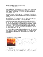
The PIC18F252 and PIC18F452 each have 32 Kbytes
of FLASH memory, while the PIC18F242 and
PIC18F442 have 16 Kbytes of FLASH. This means that
PIC18FX52 devices can store up to 16K of single word
instructions, and PIC18FX42 devices can store up to
8K of single word instructions.
The RESET vector address is at 0000h and the
interrupt vector addresses are at 0008h and 0018h.
Figure 4-1 shows the Program Memory Map for
PIC18F242/442 devices and Figure 4-2 shows the
Program Memory Map for PIC18F252/452 devices.
PIC18FXX2
DS39564C-page 36 © 2006 Microchip Technology Inc.
FIGURE 4-1: PROGRAM MEMORY MAP
AND STACK FOR
PIC18F442/242
FIGURE 4-2: PROGRAM MEMORY MAP
AND STACK FOR
PIC18F452/252
PC<20:0>
Stack Level 1
•
Stack Level 31
RESET Vector
Low Priority Interrupt Vector
•
•
CALL,RCALL,RETURN
RETFIE,RETLW
21
0000h
0018h
On-Chip
Program Memory
High Priority Interrupt Vector
0008h
User Memory Space
1FFFFFh
4000h
3FFFh
Read '0'
200000h
PC<20:0>
Stack Level 1
•
Stack Level 31
RESET Vector
Low Priority Interrupt Vector
•
•
CALL,RCALL,RETURN
RETFIE,RETLW
21
0000h
0018h
8000h
7FFFh
On-Chip
Program Memory
High Priority Interrupt Vector
0008h
User Memory Space
Read '0'
1FFFFFh
200000h
© 2006 Microchip Technology Inc. DS39564C-page 37
PIC18FXX2
4.2 Return Address Stack
The return address stack allows any combination of up
to 31 program calls and interrupts to occur. The PC
(Program Counter) is pushed onto the stack when a
CALL or RCALL instruction is executed, or an interrupt
is acknowledged. The PC value is pulled off the stack
on a RETURN, RETLW or a RETFIE instruction.
PCLATU and PCLATH are not affected by any of the
RETURN or CALL instructions.
The stack operates as a 31-word by 21-bit RAM and a
5-bit stack pointer, with the stack pointer initialized to
00000b after all RESETS. There is no RAM associated
with stack pointer 00000b. This is only a RESET value.
During a CALL type instruction, causing a push onto the
stack, the stack pointer is first incremented and the
RAM location pointed to by the stack pointer is written
with the contents of the PC. During a RETURN type
instruction, causing a pop from the stack, the contents
of the RAM location pointed to by the STKPTR are
transferred to the PC and then the stack pointer is
decremented.
The stack space is not part of either program or data
space. The stack pointer is readable and writable, and
the address on the top of the stack is readable and writ-
able through SFR registers. Data can also be pushed
to, or popped from, the stack using the top-of-stack
SFRs. Status bits indicate if the stack pointer is at, or
beyond the 31 levels provided.
4.2.1 TOP-OF-STACK ACCESS
The top of the stack is readable and writable. Three
register locations, TOSU, TOSH and TOSL hold the
contents of the stack location pointed to by the
STKPTR register. This allows users to implement a
software stack if necessary. After a CALL, RCALL or
interrupt, the software can read the pushed value by
reading the TOSU, TOSH and TOSL registers. These
values can be placed on a user defined software stack.
At return time, the software can replace the TOSU,
TOSH and TOSL and do a return.
The user must disable the global interrupt enable bits
during this time to prevent inadvertent stack
operations.
4.2.2 RETURN STACK POINTER
(STKPTR)
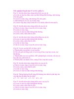
The STKPTR register contains the stack pointer value,
the STKFUL (stack full) status bit, and the STKUNF
(stack underflow) status bits. Register 4-1 shows the
STKPTR register. The value of the stack pointer can be
0 through 31. The stack pointer increments when val-
ues are pushed onto the stack and decrements when
values are popped off the stack. At RESET, the stack
pointer value will be 0. The user may read and write the
stack pointer value. This feature can be used by a Real
Time Operating System for return stack maintenance.
After the PC is pushed onto the stack 31 times (without
popping any values off the stack), the STKFUL bit is
set. The STKFUL bit can only be cleared in software or
by a POR.
The action that takes place when the stack becomes
full depends on the state of the STVREN (Stack Over-
flow Reset Enable) configuration bit. Refer to
Section 20.0 for a description of the device configura-
tion bits. If STVREN is set (default), the 31st push will
push the (PC + 2) value onto the stack, set the STKFUL
bit, and reset the device. The STKFUL bit will remain
set and the stack pointer will be set to ‘0’.
If STVREN is cleared, the STKFUL bit will be set on the
31st push and the stack pointer will increment to 31.
Any additional pushes will not overwrite the 31st push,
and STKPTR will remain at 31.
When the stack has been popped enough times to
unload the stack, the next pop will return a value of zero
to the PC and sets the STKUNF bit, while the stack
pointer remains at 0. The STKUNF bit will remain set
until cleared in software or a POR occurs.
Note: Returning a value of zero to the PC on an
underflow has the effect of vectoring the
program to the RESET vector, where the
stack conditions can be verified and
appropriate actions can be taken.
PIC18FXX2
DS39564C-page 38 © 2006 Microchip Technology Inc.
REGISTER 4-1: STKPTR REGISTER
FIGURE 4-3: RETURN ADDRESS STACK AND ASSOCIATED REGISTERS
4.2.3 PUSH AND POP INSTRUCTIONS
Since the Top-of-Stack (TOS) is readable and writable,
the ability to push values onto the stack and pull values
off the stack without disturbing normal program execu-
tion is a desirable option. To push the current PC value
onto the stack, a PUSH instruction can be executed.
This will increment the stack pointer and load the cur-
rent PC value onto the stack. TOSU, TOSH and TOSL
can then be modified to place a return address on the
stack.
The ability to pull the TOS value off of the stack and
replace it with the value that was previously pushed
onto the stack, without disturbing normal execution, is
achieved by using the POP instruction. The POP instruc-
tion discards the current TOS by decrementing the
stack pointer. The previous value pushed onto the
stack then becomes the TOS value.
4.2.4 STACK FULL/UNDERFLOW RESETS
These resets are enabled by programming the
STVREN configuration bit. When the STVREN bit is
disabled, a full or underflow condition will set the appro-
priate STKFUL or STKUNF bit, but not cause a device
RESET. When the STVREN bit is enabled, a full or
underflow will set the appropriate STKFUL or STKUNF
bit and then cause a device RESET. The STKFUL or
STKUNF bits are only cleared by the user software or
a POR Reset.
R/C-0 R/C-0 U-0 R/W-0 R/W-0 R/W-0 R/W-0 R/W-0
STKOVF STKUNF
— SP4 SP3 SP2 SP1 SP0
bit 7 bit 0
bit 7
(1)
STKOVF: Stack Full Flag bit
1 = Stack became full or overflowed
0 = Stack has not become full or overflowed
bit 6
(1)
STKUNF: Stack Underflow Flag bit
1 = Stack underflow occurred
0 = Stack underflow did not occur
bit 5 Unimplemented: Read as '0'
bit 4-0 SP4:SP0: Stack Pointer Location bits
Note 1: Bit 7 and bit 6 can only be cleared in user software or by a POR.
Legend:
R = Readable bit W = Writable bit U = Unimplemented bit, read as ‘0’
- n = Value at POR ’1’ = Bit is set ’0’ = Bit is cleared x = Bit is unknown
00011
0x001A34
11111
11110
11101
00010
00001
00000
00010
Return Address Stack
Top of Stack
0x000D58
TOSLTOSHTOSU
0x340x1A0x00
STKPTR<4:0>
© 2006 Microchip Technology Inc. DS39564C-page 39
PIC18FXX2
4.3 Fast Register Stack
A “fast interrupt return” option is available for interrupts.
A Fast Register Stack is provided for the STATUS,
WREG and BSR registers and are only one in depth.
The stack is not readable or writable and is loaded with
the current value of the corresponding register when
the processor vectors for an interrupt. The values in the
registers are then loaded back into the working regis-
ters, if the FAST RETURN instruction is used to return
from the interrupt.
A low or high priority interrupt source will push values
into the stack registers. If both low and high priority
interrupts are enabled, the stack registers cannot be
used reliably for low priority interrupts. If a high priority
interrupt occurs while servicing a low priority interrupt,
the stack register values stored by the low priority inter-
rupt will be overwritten.
If high priority interrupts are not disabled during low pri-
ority interrupts, users must save the key registers in
software during a low priority interrupt.
If no interrupts are used, the fast register stack can be
used to restore the STATUS, WREG and BSR registers
at the end of a subroutine call. To use the fast register
stack for a subroutine call, a FAST CALL instruction
must be executed.
Example 4-1 shows a source code example that uses
the fast register stack.
EXAMPLE 4-1: FAST REGISTER STACK
CODE EXAMPLE
4.4 PCL, PCLATH and PCLATU
The program counter (PC) specifies the address of the
instruction to fetch for execution. The PC is 21-bits
wide. The low byte is called the PCL register. This reg-
ister is readable and writable. The high byte is called
the PCH register. This register contains the PC<15:8>
bits and is not directly readable or writable. Updates to
the PCH register may be performed through the
PCLATH register. The upper byte is called PCU. This
register contains the PC<20:16> bits and is not directly
readable or writable. Updates to the PCU register may
be performed through the PCLATU register.
The PC addresses bytes in the program memory. To
prevent the PC from becoming misaligned with word
instructions, the LSB of PCL is fixed to a value of ’0’.
The PC increments by 2 to address sequential
instructions in the program memory.
The CALL, RCALL, GOTO and program branch
instructions write to the program counter directly. For
these instructions, the contents of PCLATH and
PCLATU are not transferred to the program counter.
The contents of PCLATH and PCLATU will be trans-
ferred to the program counter by an operation that
writes PCL. Similarly, the upper two bytes of the pro-
gram counter will be transferred to PCLATH and
PCLATU by an operation that reads PCL. This is useful
for computed offsets to the PC (see Section 4.8.1).
4.5 Clocking Scheme/Instruction
Cycle
The clock input (from OSC1) is internally divided by
four to generate four non-overlapping quadrature
clocks, namely Q1, Q2, Q3 and Q4. Internally, the pro-
gram counter (PC) is incremented every Q1, the
instruction is fetched from the program memory and
latched into the instruction register in Q4. The instruc-
tion is decoded and executed during the following Q1
through Q4. The clocks and instruction execution flow
are shown in Figure 4-4.
FIGURE 4-4: CLOCK/INSTRUCTION CYCLE
CALL SUB1, FAST ;STATUS, WREG, BSR
;SAVED IN FAST REGISTER
;STACK
•
•
SUB1 •
•
•
RETURN FAST ;RESTORE VALUES SAVED
;IN FAST REGISTER STACK
Q1
Q2 Q3 Q4
Q1
Q2 Q3 Q4
Q1
Q2 Q3 Q4
OSC1
Q1
Q2
Q3
Q4
PC
OSC2/CLKO
(RC mode)
PC
PC+2
PC+4
Fetch INST (PC)
Execute INST (PC-2)
Fetch INST (PC+2)
Execute INST (PC)
Fetch INST (PC+4)
Execute INST (PC+2)
Internal
Phase
Clock
PIC18FXX2
DS39564C-page 40 © 2006 Microchip Technology Inc.
4.6 Instruction Flow/Pipelining
An “Instruction Cycle” consists of four Q cycles (Q1,
Q2, Q3 and Q4). The instruction fetch and execute are
pipelined such that fetch takes one instruction cycle,
while decode and execute takes another instruction
cycle. However, due to the pipelining, each instruction
effectively executes in one cycle. If an instruction
causes the program counter to change (e.g., GOTO)
then two cycles are required to complete the instruction
(Example 4-2).
A fetch cycle begins with the program counter (PC)
incrementing in Q1.
In the execution cycle, the fetched instruction is latched
into the “Instruction Register” (IR) in cycle Q1. This
instruction is then decoded and executed during the
Q2, Q3, and Q4 cycles. Data memory is read during Q2
(operand read) and written during Q4 (destination
write).
EXAMPLE 4-2: INSTRUCTION PIPELINE FLOW
4.7 Instructions in Program Memory
The program memory is addressed in bytes. Instruc-
tions are stored as two bytes or four bytes in program
memory. The Least Significant Byte of an instruction
word is always stored in a program memory location
with an even address (LSB =’0’). Figure 4-5 shows an
example of how instruction words are stored in the pro-
gram memory. To maintain alignment with instruction
boundaries, the PC increments in steps of 2 and the
LSB will always read ’0’ (see Section 4.4).
The CALL and GOTO instructions have an absolute pro-
gram memory address embedded into the instruction.
Since instructions are always stored on word bound-
aries, the data contained in the instruction is a word
address. The word address is written to PC<20:1>,
which accesses the desired byte address in program
memory. Instruction #2 in Figure 4-5 shows how the
instruction “GOTO 000006h’ is encoded in the program
memory. Program branch instructions which encode a
relative address offset operate in the same manner.
The offset value stored in a branch instruction repre-
sents the number of single word instructions that the
PC will be offset by. Section 20.0 provides further
details of the instruction set.
FIGURE 4-5: INSTRUCTIONS IN PROGRAM MEMORY
All instructions are single cycle, except for any program branches. These take two cycles since the fetch instruction
is “flushed” from the pipeline while the new instruction is being fetched and then executed.
TCY0TCY1TCY2TCY3TCY4TCY5
1. MOVLW 55h
Fetch 1 Execute 1
2. MOVWF PORTB
Fetch 2 Execute 2
3. BRA SUB_1
Fetch 3 Execute 3
4. BSF PORTA, BIT3 (Forced NOP)
Fetch 4 Flush (NOP)
5. Instruction @ address SUB_1
Fetch SUB_1 Execute SUB_1
Word Address
LSB = 1 LSB = 0 ↓
Program Memory
Byte Locations
→
000000h
000002h
000004h
000006h
Instruction 1:
MOVLW 055h
0Fh 55h 000008h
Instruction 2:
GOTO 000006h
EFh 03h 00000Ah
F0h 00h 00000Ch
Instruction 3:
MOVFF 123h, 456h
C1h 23h 00000Eh
F4h 56h 000010h
000012h
000014h
© 2006 Microchip Technology Inc. DS39564C-page 41
PIC18FXX2
4.7.1 TWO-WORD INSTRUCTIONS
The PIC18FXX2 devices have four two-word instruc-
tions: MOVFF, CALL, GOTO and LFSR. The second
word of these instructions has the 4 MSBs set to 1’s
and is a special kind of NOP instruction. The lower 12
bits of the second word contain data to be used by the
instruction. If the first word of the instruction is exe-
cuted, the data in the second word is accessed. If the
second word of the instruction is executed by itself (first
word was skipped), it will execute as a NOP. This action
is necessary when the two-word instruction is preceded
by a conditional instruction that changes the PC. A pro-
gram example that demonstrates this concept is shown
in Example 4-3. Refer to Section 20.0 for further details
of the instruction set.
EXAMPLE 4-3: TWO-WORD INSTRUCTIONS
4.8 Lookup Tables
Lookup tables are implemented two ways. These are:
• Computed GOTO
• Table Reads
4.8.1 COMPUTED GOTO
A computed GOTO is accomplished by adding an offset
to the program counter (ADDWF PCL).
A lookup table can be formed with an ADDWF PCL
instruction and a group of RETLW 0xnn instructions.
WREG is loaded with an offset into the table before
executing a call to that table. The first instruction of the
called routine is the ADDWF PCL instruction. The next
instruction executed will be one of the RETLW 0xnn
instructions, that returns the value 0xnn to the calling
function.
The offset value (value in WREG) specifies the number
of bytes that the program counter should advance.
In this method, only one data byte may be stored in
each instruction location and room on the return
address stack is required.
4.8.2 TABLE READS/TABLE WRITES
A better method of storing data in program memory
allows 2 bytes of data to be stored in each instruction
location.
Lookup table data may be stored 2 bytes per program
word by using table reads and writes. The table pointer
(TBLPTR) specifies the byte address and the table
latch (TABLAT) contains the data that is read from, or
written to program memory. Data is transferred to/from
program memory, one byte at a time.
A description of the Table Read/Table Write operation
is shown in Section 3.0.
CASE 1:
Object Code Source Code
0110 0110 0000 0000 TSTFSZ REG1 ; is RAM location 0?
1100 0001 0010 0011 MOVFF REG1, REG2 ; No, execute 2-word instruction
1111 0100 0101 0110 ; 2nd operand holds address of REG2
0010 0100 0000 0000 ADDWF REG3 ; continue code
CASE 2:
Object Code Source Code
0110 0110 0000 0000 TSTFSZ REG1 ; is RAM location 0?
1100 0001 0010 0011 MOVFF REG1, REG2 ; Yes
1111 0100 0101 0110 ; 2nd operand becomes NOP
0010 0100 0000 0000 ADDWF REG3 ; continue code
Note: The ADDWF PCL instruction does not
update PCLATH and PCLATU. A read
operation on PCL must be performed to
update PCLATH and PCLATU.
PIC18FXX2
DS39564C-page 42 © 2006 Microchip Technology Inc.
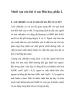
4.9 Data Memory Organization
The data memory is implemented as static RAM. Each
register in the data memory has a 12-bit address,
allowing up to 4096 bytes of data memory. Figure 4-6
and Figure 4-7 show the data memory organization for
the PIC18FXX2 devices.
The data memory map is divided into as many as 16
banks that contain 256 bytes each. The lower 4 bits of
the Bank Select Register (BSR<3:0>) select which
bank will be accessed. The upper 4 bits for the BSR are
not implemented.
The data memory contains Special Function Registers
(SFR) and General Purpose Registers (GPR). The
SFRs are used for control and status of the controller
and peripheral functions, while GPRs are used for data
storage and scratch pad operations in the user’s appli-
cation. The SFRs start at the last location of Bank 15
(0xFFF) and extend downwards. Any remaining space
beyond the SFRs in the Bank may be implemented as
GPRs. GPRs start at the first location of Bank 0 and
grow upwards. Any read of an unimplemented location
will read as ’0’s.
The entire data memory may be accessed directly or
indirectly. Direct addressing may require the use of the
BSR register. Indirect addressing requires the use of a
File Select Register (FSRn) and a corresponding Indi-
rect File Operand (INDFn). Each FSR holds a 12-bit
address value that can be used to access any location
in the Data Memory map without banking.
The instruction set and architecture allow operations
across all banks. This may be accomplished by indirect
addressing or by the use of the MOVFF instruction. The
MOVFF instruction is a two-word/two-cycle instruction
that moves a value from one register to another.
To ensure that commonly used registers (SFRs and
select GPRs) can be accessed in a single cycle,
regardless of the current BSR values, an Access Bank
is implemented. A segment of Bank 0 and a segment of
Bank 15 comprise the Access RAM. Section 4.10
provides a detailed description of the Access RAM.
4.9.1 GENERAL PURPOSE REGISTER
FILE
The register file can be accessed either directly or indi-
rectly. Indirect addressing operates using a File Select
Register and corresponding Indirect File Operand. The
operation of indirect addressing is shown in
Section 4.12.
Enhanced MCU devices may have banked memory in
the GPR area. GPRs are not initialized by a Power-on
Reset and are unchanged on all other RESETS.
Data RAM is available for use as GPR registers by all
instructions. The top half of Bank 15 (0xF80 to 0xFFF)
contains SFRs. All other banks of data memory contain
GPR registers, starting with Bank 0.
4.9.2 SPECIAL FUNCTION REGISTERS
The Special Function Registers (SFRs) are registers
used by the CPU and Peripheral Modules for control-
ling the desired operation of the device. These regis-
ters are implemented as static RAM. A list of these
registers is given in Table 4-1 and Table 4-2.
The SFRs can be classified into two sets; those asso-
ciated with the “core” function and those related to the
peripheral functions. Those registers related to the
“core” are described in this section, while those related
to the operation of the peripheral features are
described in the section of that peripheral feature.
The SFRs are typically distributed among the
peripherals whose functions they control.
The unused SFR locations will be unimplemented and
read as '0's. See Table 4-1 for addresses for the SFRs.
© 2006 Microchip Technology Inc. DS39564C-page 43
PIC18FXX2
FIGURE 4-6: DATA MEMORY MAP FOR PIC18F242/442
Bank 0
Bank 1
Bank 14
Bank 15
Data Memory Map
BSR<3:0>
= 0000
= 0001
= 1111
080h
07Fh
F80h
FFFh
00h
7Fh
80h
FFh
Access Bank
When a = 0,
the BSR is ignored and the
Access Bank is used.
The first 128 bytes are General
Purpose RAM (from Bank 0).
The second 128 bytes are
Special Function Registers
(from Bank 15).
When a = 1,
the BSR is used to specify the
RAM location that the
instruction uses.
F7Fh
F00h
EFFh
1FFh
100h
0FFh
000h
Access RAM
FFh
00h
FFh
00h
FFh
00h
GPR
GPR
SFR
Unused
Access RAM high
Access RAM low
Bank 3
to
200h
Unused
Read ’00h’
= 1110
= 0011
(SFRs)
GPR
2FFh
300h
FFh
00h
Bank 2
= 0010
PIC18FXX2
DS39564C-page 44 © 2006 Microchip Technology Inc.
FIGURE 4-7: DATA MEMORY MAP FOR PIC18F252/452
Bank 0
Bank 1
Bank 14
Bank 15
Data Memory Map
BSR<3:0>
= 0000
= 0001
= 1110
= 1111
080h
07Fh
F80h
FFFh
00h
7Fh
80h
FFh
Access Bank
When a = 0,
the BSR is ignored and the
Access Bank is used.
The first 128 bytes are General
Purpose RAM (from Bank 0).
The second 128 bytes are
Special Function Registers
(from Bank 15).
When a = 1,
the BSR is used to specify the
RAM location that the
instruction uses.
Bank 4
Bank 3
Bank 2
F7Fh
F00h
EFFh
3FFh
300h
2FFh
200h
1FFh
100h
0FFh
000h
= 0110
= 0101
= 0011
= 0010
Access RAM
FFh
00h
FFh
00h
FFh
00h
FFh
00h
FFh
00h
FFh
00h
GPR
GPR
GPR
GPR
SFR
Unused
Access RAM high
Access RAM low
Bank 5
GPR
GPR
Bank 6
to
4FFh
400h
5FFh
500h
600h
Unused
Read ’00h’
= 0100
(SFR’s)
© 2006 Microchip Technology Inc. DS39564C-page 45
PIC18FXX2
TABLE 4-1: SPECIAL FUNCTION REGISTER MAP
Address Name Address Name Address Name Address Name
FFFh TOSU FDFh INDF2
(3)
FBFh CCPR1H F9Fh IPR1
FFEh TOSH FDEh POSTINC2
(3)
FBEh CCPR1L F9Eh PIR1
FFDh TOSL FDDh POSTDEC2
(3)
FBDh CCP1CON F9Dh PIE1
FFCh STKPTR FDCh PREINC2
(3)
FBCh CCPR2H F9Ch —
FFBh PCLATU FDBh PLUSW2
(3)
FBBh CCPR2L F9Bh —
FFAh PCLATH FDAh FSR2H FBAh CCP2CON F9Ah —
FF9h PCL FD9h FSR2L FB9h — F99h —
FF8h TBLPTRU FD8h STATUS FB8h — F98h —
FF7h TBLPTRH FD7h TMR0H FB7h — F97h —
FF6h TBLPTRL FD6h TMR0L FB6h — F96h TRISE
(2)
FF5h TABLAT FD5h T0CON FB5h — F95h TRISD
(2)
FF4h PRODH FD4h — FB4h — F94h TRISC
FF3h PRODL FD3h OSCCON FB3h TMR3H F93h TRISB
FF2h INTCON FD2h LVDCON FB2h TMR3L F92h TRISA
FF1h INTCON2 FD1h WDTCON FB1h T3CON F91h —
FF0h INTCON3 FD0h RCON FB0h — F90h —
FEFh INDF0
(3)
FCFh TMR1H FAFh SPBRG F8Fh —
FEEh POSTINC0
(3)
FCEh TMR1L FAEh RCREG F8Eh —
FEDh POSTDEC0
(3)
FCDh T1CON FADh TXREG F8Dh LATE
(2)
FECh PREINC0
(3)
FCCh TMR2 FACh TXSTA F8Ch LATD
(2)
FEBh PLUSW0
(3)
FCBh PR2 FABh RCSTA F8Bh LATC
FEAh FSR0H FCAh T2CON FAAh — F8Ah LATB
FE9h FSR0L FC9h SSPBUF FA9h EEADR F89h LATA
FE8h WREG FC8h SSPADD FA8h EEDATA F88h —
FE7h INDF1
(3)
FC7h SSPSTAT FA7h EECON2 F87h —
FE6h POSTINC1
(3)
FC6h SSPCON1 FA6h EECON1 F86h —
FE5h POSTDEC1
(3)
FC5h SSPCON2 FA5h — F85h —
FE4h PREINC1
(3)
FC4h ADRESH FA4h — F84h PORTE
(2)
FE3h PLUSW1
(3)
FC3h ADRESL FA3h — F83h PORTD
(2)
FE2h FSR1H FC2h ADCON0 FA2h IPR2 F82h PORTC
FE1h FSR1L FC1h ADCON1 FA1h PIR2 F81h PORTB
FE0h BSR FC0h — FA0h PIE2 F80h PORTA
Note 1: Unimplemented registers are read as ’0’.
2: This register is not available on PIC18F2X2 devices.
3: This is not a physical register.
PIC18FXX2
DS39564C-page 46 © 2006 Microchip Technology Inc.
TABLE 4-2: REGISTER FILE SUMMARY
File Name Bit 7 Bit 6 Bit 5 Bit 4 Bit 3 Bit 2 Bit 1 Bit 0
Value on
POR, BOR
Details
on page:
TOSU
— — — Top-of-Stack upper Byte (TOS<20:16>) 0 0000 37
TOSH Top-of-Stack High Byte (TOS<15:8>) 0000 0000 37
TOSL Top-of-Stack Low Byte (TOS<7:0>) 0000 0000 37
STKPTR STKFUL STKUNF — Return Stack Pointer 00-0 0000 38
PCLATU
— — — Holding Register for PC<20:16> 0 0000 39
PCLATH Holding Register for PC<15:8> 0000 0000 39
PCL PC Low Byte (PC<7:0>) 0000 0000 39
TBLPTRU
— —bit21
(2)
Program Memory Table Pointer Upper Byte (TBLPTR<20:16>) 00 0000 58
TBLPTRH Program Memory Table Pointer High Byte (TBLPTR<15:8>) 0000 0000 58
TBLPTRL Program Memory Table Pointer Low Byte (TBLPTR<7:0>) 0000 0000 58
TABLAT Program Memory Table Latch 0000 0000 58
PRODH Product Register High Byte xxxx xxxx 71
PRODL Product Register Low Byte xxxx xxxx 71
INTCON GIE/GIEH PEIE/GIEL TMR0IE INT0IE RBIE TMR0IF INT0IF RBIF 0000 000x 75
INTCON2 RBPU INTEDG0 INTEDG1 INTEDG2
—TMR0IP—RBIP1111 -1-1 76
INTCON3 INT2IP INT1IP
— INT2IE INT1IE — INT2IF INT1IF 11-0 0-00 77
INDF0 Uses contents of FSR0 to address data memory - value of FSR0 not changed (not a physical register) n/a 50
POSTINC0 Uses contents of FSR0 to address data memory - value of FSR0 post-incremented (not a physical register) n/a 50
POSTDEC0 Uses contents of FSR0 to address data memory - value of FSR0 post-decremented (not a physical register) n/a 50
PREINC0 Uses contents of FSR0 to address data memory - value of FSR0 pre-incremented (not a physical register) n/a 50
PLUSW0 Uses contents of FSR0 to address data memory - value of FSR0 (not a physical register).
Offset by value in WREG.
n/a 50
FSR0H
— — — — Indirect Data Memory Address Pointer 0 High Byte 0000 50
FSR0L Indirect Data Memory Address Pointer 0 Low Byte xxxx xxxx 50
WREG Working Register xxxx xxxx n/a
INDF1 Uses contents of FSR1 to address data memory - value of FSR1 not changed (not a physical register) n/a 50
POSTINC1 Uses contents of FSR1 to address data memory - value of FSR1 post-incremented (not a physical register) n/a 50
POSTDEC1 Uses contents of FSR1 to address data memory - value of FSR1 post-decremented (not a physical register) n/a 50
PREINC1 Uses contents of FSR1 to address data memory - value of FSR1 pre-incremented (not a physical register) n/a 50
PLUSW1 Uses contents of FSR1 to address data memory - value of FSR1 (not a physical register).
Offset by value in WREG.
n/a 50
FSR1H
— — — — Indirect Data Memory Address Pointer 1 High Byte 0000 50
FSR1L Indirect Data Memory Address Pointer 1 Low Byte xxxx xxxx 50
BSR
— — — — Bank Select Register 0000 49
INDF2 Uses contents of FSR2 to address data memory - value of FSR2 not changed (not a physical register) n/a 50
POSTINC2 Uses contents of FSR2 to address data memory - value of FSR2 post-incremented (not a physical register) n/a 50
POSTDEC2 Uses contents of FSR2 to address data memory - value of FSR2 post-decremented (not a physical register) n/a 50
PREINC2 Uses contents of FSR2 to address data memory - value of FSR2 pre-incremented (not a physical register) n/a 50
PLUSW2 Uses contents of FSR2 to address data memory - value of FSR2 (not a physical register).
Offset by value in WREG.
n/a 50
FSR2H
— — — — Indirect Data Memory Address Pointer 2 High Byte 0000 50
FSR2L Indirect Data Memory Address Pointer 2 Low Byte xxxx xxxx 50
STATUS
— — —NOVZDCC x xxxx 52
TMR0H Timer0 Register High Byte 0000 0000 105
TMR0L Timer0 Register Low Byte xxxx xxxx 105
T0CON TMR0ON T08BIT T0CS T0SE PSA T0PS2 T0PS1 T0PS0 1111 1111 103
Legend: x = unknown, u = unchanged, - = unimplemented, q = value depends on condition
Note 1: RA6 and associated bits are configured as port pins in RCIO and ECIO Oscillator mode only and read '0' in all other Oscillator modes.
2: Bit 21 of the TBLPTRU allows access to the device configuration bits.
3: These registers and bits are reserved on the PIC18F2X2 devices; always maintain these clear.
© 2006 Microchip Technology Inc. DS39564C-page 47
PIC18FXX2
OSCCON — — — — — — —SCS 0 21
LVDCON
— — IRVST LVDEN LVDL3 LVDL2 LVDL1 LVDL0 00 0101 191
WDTCON
— — — — — — —SWDTE 0 203
RCON IPEN
— —RITO PD POR BOR 0 1 11qq 53, 28, 84
TMR1H Timer1 Register High Byte xxxx xxxx 107
TMR1L Timer1 Register Low Byte xxxx xxxx 107
T1CON RD16
— T1CKPS1 T1CKPS0 T1OSCEN T1SYNC TMR1CS TMR1ON 0-00 0000 107
TMR2 Timer2 Register 0000 0000 111
PR2 Timer2 Period Register 1111 1111 112
T2CON
— TOUTPS3 TOUTPS2 TOUTPS1 TOUTPS0 TMR2ON T2CKPS1 T2CKPS0 -000 0000 111
SSPBUF SSP Receive Buffer/Transmit Register xxxx xxxx 125
SSPADD SSP Address Register in I
2
C Slave mode. SSP Baud Rate Reload Register in I
2
C Master mode. 0000 0000 134
SSPSTAT SMP CKE D/A
PSR/WUA BF 0000 0000 126
SSPCON1 WCOL SSPOV SSPEN CKP SSPM3 SSPM2 SSPM1 SSPM0 0000 0000 127
SSPCON2 GCEN ACKSTAT ACKDT ACKEN RCEN PEN RSEN SEN 0000 0000 137
ADRESH A/D Result Register High Byte xxxx xxxx 187,188
ADRESL A/D Result Register Low Byte xxxx xxxx 187,188
ADCON0 ADCS1 ADCS0 CHS2 CHS1 CHS0 GO/DONE
—ADON0000 00-0 181
ADCON1 ADFM ADCS2
— — PCFG3 PCFG2 PCFG1 PCFG0 00 0000 182
CCPR1H Capture/Compare/PWM Register1 High Byte xxxx xxxx 121, 123
CCPR1L Capture/Compare/PWM Register1 Low Byte xxxx xxxx 121, 123
CCP1CON
— — DC1B1 DC1B0 CCP1M3 CCP1M2 CCP1M1 CCP1M0 00 0000 117
CCPR2H Capture/Compare/PWM Register2 High Byte xxxx xxxx 121, 123
CCPR2L Capture/Compare/PWM Register2 Low Byte xxxx xxxx 121, 123
CCP2CON
— — DC2B1 DC2B0 CCP2M3 CCP2M2 CCP2M1 CCP2M0 00 0000 117
TMR3H Timer3 Register High Byte xxxx xxxx 113
TMR3L Timer3 Register Low Byte xxxx xxxx 113
T3CON RD16 T3CCP2 T3CKPS1 T3CKPS0 T3CCP1 T3SYNC
TMR3CS TMR3ON 0000 0000 113
SPBRG USART1 Baud Rate Generator 0000 0000 168
RCREG USART1 Receive Register 0000 0000 175, 178,
180
TXREG USART1 Transmit Register 0000 0000 173, 176,
179
TXSTA CSRC TX9 TXEN SYNC
— BRGH TRMT TX9D 0000 -010 166
RCSTA SPEN RX9 SREN CREN ADDEN FERR OERR RX9D 0000 000x 167
EEADR Data EEPROM Address Register 0000 0000 65, 69
EEDATA Data EEPROM Data Register 0000 0000 69
EECON2 Data EEPROM Control Register 2 (not a physical register) 65, 69
EECON1 EEPGD CFGS
— FREE WRERR WREN WR RD xx-0 x000 66
TABLE 4-2: REGISTER FILE SUMMARY (CONTINUED)
File Name Bit 7 Bit 6 Bit 5 Bit 4 Bit 3 Bit 2 Bit 1 Bit 0
Value on
POR, BOR
Details
on page:
Legend: x = unknown, u = unchanged, - = unimplemented, q = value depends on condition
Note 1: RA6 and associated bits are configured as port pins in RCIO and ECIO Oscillator mode only and read '0' in all other Oscillator modes.
2: Bit 21 of the TBLPTRU allows access to the device configuration bits.
3: These registers and bits are reserved on the PIC18F2X2 devices; always maintain these clear.
PIC18FXX2
DS39564C-page 48 © 2006 Microchip Technology Inc.
IPR2 — — — EEIP BCLIP LVDIP TMR3IP CCP2IP 1 1111 83
PIR2
— — — EEIF BCLIF LVDIF TMR3IF CCP2IF 0 0000 79
PIE2
— — — EEIE BCLIE LVDIE TMR3IE CCP2IE 0 0000 81
IPR1 PSPIP
(3)
ADIP RCIP TXIP SSPIP CCP1IP TMR2IP TMR1IP 1111 1111 82
PIR1 PSPIF
(3)
ADIF RCIF TXIF SSPIF CCP1IF TMR2IF TMR1IF 0000 0000 78
PIE1 PSPIE
(3)
ADIE RCIE TXIE SSPIE CCP1IE TMR2IE TMR1IE 0000 0000 80
TRISE
(3)
IBF OBF IBOV PSPMODE — Data Direction bits for PORTE 0000 -111 98
TRISD
(3)
Data Direction Control Register for PORTD 1111 1111 96
TRISC Data Direction Control Register for PORTC 1111 1111 93
TRISB Data Direction Control Register for PORTB 1111 1111 90
TRISA
—TRISA6
(1)
Data Direction Control Register for PORTA -111 1111 87
LATE
(3)
— — — — — Read PORTE Data Latch,
Write PORTE Data Latch
-xxx 99
LATD
(3)
Read PORTD Data Latch, Write PORTD Data Latch xxxx xxxx 95
LATC Read PORTC Data Latch, Write PORTC Data Latch xxxx xxxx 93
LATB Read PORTB Data Latch, Write PORTB Data Latch xxxx xxxx 90
LATA
—LATA6
(1)
Read PORTA Data Latch, Write PORTA Data Latch
(1)
-xxx xxxx 87
PORTE
(3)
Read PORTE pins, Write PORTE Data Latch -000 99
PORTD
(3)
Read PORTD pins, Write PORTD Data Latch xxxx xxxx 95
PORTC Read PORTC pins, Write PORTC Data Latch xxxx xxxx 93
PORTB Read PORTB pins, Write PORTB Data Latch xxxx xxxx 90
PORTA
—RA6
(1)
Read PORTA pins, Write PORTA Data Latch
(1)
-x0x 0000 87
TABLE 4-2: REGISTER FILE SUMMARY (CONTINUED)
File Name Bit 7 Bit 6 Bit 5 Bit 4 Bit 3 Bit 2 Bit 1 Bit 0
Value on
POR, BOR
Details
on page:
Legend: x = unknown, u = unchanged, - = unimplemented, q = value depends on condition
Note 1: RA6 and associated bits are configured as port pins in RCIO and ECIO Oscillator mode only and read '0' in all other Oscillator modes.
2: Bit 21 of the TBLPTRU allows access to the device configuration bits.
3: These registers and bits are reserved on the PIC18F2X2 devices; always maintain these clear.
© 2006 Microchip Technology Inc. DS39564C-page 49
PIC18FXX2
4.10 Access Bank
The Access Bank is an architectural enhancement
which is very useful for C compiler code optimization.
The techniques used by the C compiler may also be
useful for programs written in assembly.
This data memory region can be used for:
• Intermediate computational values
• Local variables of subroutines
• Faster context saving/switching of variables
• Common variables
• Faster evaluation/control of SFRs (no banking)
The Access Bank is comprised of the upper 128 bytes
in Bank 15 (SFRs) and the lower 128 bytes in Bank 0.
These two sections will be referred to as Access RAM
High and Access RAM Low, respectively. Figure 4-6
and Figure 4-7 indicate the Access RAM areas.
A bit in the instruction word specifies if the operation is
to occur in the bank specified by the BSR register or in
the Access Bank. This bit is denoted by the ’a’ bit (for
access bit).
When forced in the Access Bank (a = 0), the last
address in Access RAM Low is followed by the first
address in Access RAM High. Access RAM High maps
the Special Function registers, so that these registers
can be accessed without any software overhead. This is
useful for testing status flags and modifying control bits.
4.11 Bank Select Register (BSR)
The need for a large general purpose memory space
dictates a RAM banking scheme. The data memory is
partitioned into sixteen banks. When using direct
addressing, the BSR should be configured for the
desired bank.
BSR<3:0> holds the upper 4 bits of the 12-bit RAM
address. The BSR<7:4> bits will always read ’0’s, and
writes will have no effect.
A MOVLB instruction has been provided in the
instruction set to assist in selecting banks.
If the currently selected bank is not implemented, any
read will return all '0's and all writes are ignored. The
STATUS register bits will be set/cleared as appropriate
for the instruction performed.
Each Bank extends up to FFh (256 bytes). All data
memory is implemented as static RAM.
A MOVFF instruction ignores the BSR, since the 12-bit
addresses are embedded into the instruction word.
Section 4.12 provides a description of indirect address-
ing, which allows linear addressing of the entire RAM
space.
FIGURE 4-8: DIRECT ADDRESSING
Note 1: For register file map detail, see Table 4-1.
2: The access bit of the instruction can be used to force an override of the selected bank (BSR<3:0>) to the
registers of the Access Bank.
3: The MOVFF instruction embeds the entire 12-bit address in the instruction.
Data
Memory
(1)
Direct Addressing
Bank Select
(2)
Location Select
(3)
BSR<3:0> 7
0
From Opcode
(3)
00h 01h 0Eh 0Fh
Bank 0 Bank 1 Bank 14 Bank 15
1FFh
100h
0FFh
000h
EFFh
E00h
FFFh
F00h
PIC18FXX2
DS39564C-page 50 © 2006 Microchip Technology Inc.
4.12 Indirect Addressing, INDF and
FSR Registers
Indirect addressing is a mode of addressing data mem-
ory, where the data memory address in the instruction
is not fixed. An FSR register is used as a pointer to the
data memory location that is to be read or written. Since
this pointer is in RAM, the contents can be modified by
the program. This can be useful for data tables in the
data memory and for software stacks. Figure 4-9
shows the operation of indirect addressing. This shows
the moving of the value to the data memory address
specified by the value of the FSR register.
Indirect addressing is possible by using one of the
INDF registers. Any instruction using the INDF register
actually accesses the register pointed to by the File
Select Register, FSR. Reading the INDF register itself,
indirectly (FSR = 0), will read 00h. Writing to the INDF
register indirectly, results in a no operation. The FSR
register contains a 12-bit address, which is shown in
Figure 4-10.
The INDFn register is not a physical register. Address-
ing INDFn actually addresses the register whose
address is contained in the FSRn register (FSRn is a
pointer). This is indirect addressing.
Example 4-4 shows a simple use of indirect addressing
to clear the RAM in Bank1 (locations 100h-1FFh) in a
minimum number of instructions.
EXAMPLE 4-4: HOW TO CLEAR RAM
(BANK1) USING INDIRECT
ADDRESSING
There are three indirect addressing registers. To
address the entire data memory space (4096 bytes),
these registers are 12-bit wide. To store the 12-bits of
addressing information, two 8-bit registers are
required. These indirect addressing registers are:
1. FSR0: composed of FSR0H:FSR0L
2. FSR1: composed of FSR1H:FSR1L
3. FSR2: composed of FSR2H:FSR2L
In addition, there are registers INDF0, INDF1 and
INDF2, which are not physically implemented. Reading
or writing to these registers activates indirect address-
ing, with the value in the corresponding FSR register
being the address of the data. If an instruction writes a
value to INDF0, the value will be written to the address
pointed to by FSR0H:FSR0L. A read from INDF1 reads
the data from the address pointed to by
FSR1H:FSR1L. INDFn can be used in code anywhere
an operand can be used.
If INDF0, INDF1 or INDF2 are read indirectly via an
FSR, all '0's are read (zero bit is set). Similarly, if
INDF0, INDF1 or INDF2 are written to indirectly, the
operation will be equivalent to a NOP instruction and the
STATUS bits are not affected.
4.12.1 INDIRECT ADDRESSING
OPERATION
Each FSR register has an INDF register associated
with it, plus four additional register addresses. Perform-
ing an operation on one of these five registers deter-
mines how the FSR will be modified during indirect
addressing.
When data access is done to one of the five INDFn
locations, the address selected will configure the FSRn
register to:
• Do nothing to FSRn after an indirect access (no
change) - INDFn
• Auto-decrement FSRn after an indirect access
(post-decrement) - POSTDECn
• Auto-increment FSRn after an indirect access
(post-increment) - POSTINCn
• Auto-increment FSRn before an indirect access
(pre-increment) - PREINCn
• Use the value in the WREG register as an offset
to FSRn. Do not modify the value of the WREG or
the FSRn register after an indirect access (no
change) - PLUSWn
When using the auto-increment or auto-decrement fea-
tures, the effect on the FSR is not reflected in the
STATUS register. For example, if the indirect address
causes the FSR to equal '0', the Z bit will not be set.
Incrementing or decrementing an FSR affects all 12
bits. That is, when FSRnL overflows from an increment,
FSRnH will be incremented automatically.
Adding these features allows the FSRn to be used as a
stack pointer, in addition to its uses for table operations
in data memory.
Each FSR has an address associated with it that per-
forms an indexed indirect access. When a data access
to this INDFn location (PLUSWn) occurs, the FSRn is
configured to add the signed value in the WREG regis-
ter and the value in FSR to form the address before an
indirect access. The FSR value is not changed.
If an FSR register contains a value that points to one of
the INDFn, an indirect read will read 00h (zero bit is
set), while an indirect write will be equivalent to a NOP
(STATUS bits are not affected).
If an indirect addressing operation is done where the
target address is an FSRnH or FSRnL register, the
write operation will dominate over the pre- or
post-increment/decrement functions.
LFSR FSR0 ,0x100 ;
NEXT CLRF POSTINC0 ; Clear INDF
; register and
; inc pointer
BTFSS FSR0H, 1 ; All done with
; Bank1?
GOTO NEXT ; NO, clear next
CONTINUE ; YES, continue
© 2006 Microchip Technology Inc. DS39564C-page 51
PIC18FXX2
FIGURE 4-9: INDIRECT ADDRESSING OPERATION
FIGURE 4-10: INDIRECT ADDRESSING
Opcode Address
File Address = access of an indirect addressing register
FSR
Instruction
Executed
Instruction
Fetched
RAM
Opcode
File
12
12
12
BSR<3:0>
8
4
0h
FFFh
Note 1: For register file map detail, see Table 4-1.
Data
Memory
(1)
Indirect Addressing
FSR Register11
0
0FFFh
0000h
Location Select
PIC18FXX2
DS39564C-page 52 © 2006 Microchip Technology Inc.
4.13 STATUS Register
The STATUS register, shown in Register 4-2, contains
the arithmetic status of the ALU. The STATUS register
can be the destination for any instruction, as with any
other register. If the STATUS register is the destination
for an instruction that affects the Z, DC, C, OV, or N bits,
then the write to these five bits is disabled. These bits
are set or cleared according to the device logic. There-
fore, the result of an instruction with the STATUS
register as destination may be different than intended.
For example, CLRF STATUS will clear the upper three
bits and set the Z bit. This leaves the STATUS register
as 000u u1uu (where u = unchanged).
It is recommended, therefore, that only BCF, BSF,
SWAPF, MOVFF and MOVWF instructions are used to
alter the STATUS register, because these instructions
do not affect the Z, C, DC, OV, or N bits from the
STATUS register. For other instructions not affecting
any status bits, see Table 20-2.
REGISTER 4-2: STATUS REGISTER
Note: The C and DC bits operate as a borrow and
digit borrow
bit respectively, in subtraction.
U-0 U-0 U-0 R/W-x R/W-x R/W-x R/W-x R/W-x
— — —NOVZDCC
bit 7 bit 0
bit 7-5 Unimplemented: Read as '0'
bit 4 N: Negative bit
This bit is used for signed arithmetic (2’s complement). It indicates whether the result was
negative (ALU MSB = 1).
1 = Result was negative
0 = Result was positive
bit 3 OV: Overflow bit
This bit is used for signed arithmetic (2’s complement). It indicates an overflow of the
7-bit magnitude, which causes the sign bit (bit7) to change state.
1 = Overflow occurred for signed arithmetic (in this arithmetic operation)
0 = No overflow occurred
bit 2 Z: Zero bit
1 = The result of an arithmetic or logic operation is zero
0 = The result of an arithmetic or logic operation is not zero
bit 1 DC: Digit carry/borrow
bit
For ADDWF, ADDLW, SUBLW, and SUBWF instructions
1 = A carry-out from the 4th low order bit of the result occurred
0 = No carry-out from the 4th low order bit of the result
Note: For borrow,
the polarity is reversed. A subtraction is executed by adding the two’s
complement of the second operand. For rotate (RRF, RLF) instructions, this bit is
loaded with either the bit 4 or bit 3 of the source register.
bit 0 C: Carry/borrow bit
For ADDWF, ADDLW, SUBLW, and SUBWF instructions
1 = A carry-out from the Most Significant bit of the result occurred
0 = No carry-out from the Most Significant bit of the result occurred
Note: For borrow,
the polarity is reversed. A subtraction is executed by adding the two’s
complement of the second operand. For rotate (RRF, RLF) instructions, this bit is
loaded with either the high or low order bit of the source register.
Legend:
R = Readable bit W = Writable bit U = Unimplemented bit, read as ‘0’
- n = Value at POR ’1’ = Bit is set ’0’ = Bit is cleared x = Bit is unknown
© 2006 Microchip Technology Inc. DS39564C-page 53
PIC18FXX2
4.14 RCON Register
The Reset Control (RCON) register contains flag bits
that allow differentiation between the sources of a
device RESET. These flags include the TO
, PD, POR,
BOR
and RI bits. This register is readable and writable.
REGISTER 4-3: RCON REGISTER
Note 1: If the BOREN configuration bit is set
(Brown-out Reset enabled), the BOR
bit is
’1’ on a Power-on Reset. After a Brown-
out Reset has occurred, the BOR bit will
be cleared, and must be set by firmware to
indicate the occurrence of the next
Brown-out Reset.
2: It is recommended that the POR
bit be set
after a Power-on Reset has been
detected, so that subsequent Power-on
Resets may be detected.
R/W-0 U-0 U-0 R/W-1 R-1 R-1 R/W-0 R/W-0
IPEN — —RITO PD POR BOR
bit 7 bit 0
bit 7 IPEN: Interrupt Priority Enable bit
1 = Enable priority levels on interrupts
0 = Disable priority levels on interrupts (16CXXX Compatibility mode)
bit 6-5 Unimplemented: Read as '0'
bit 4 RI
: RESET Instruction Flag bit
1 = The RESET instruction was not executed
0 = The RESET instruction was executed causing a device RESET
(must be set in software after a Brown-out Reset occurs)
bit 3 TO
: Watchdog Time-out Flag bit
1 = After power-up, CLRWDT instruction, or SLEEP instruction
0 = A WDT time-out occurred
bit 2 PD
: Power-down Detection Flag bit
1 = After power-up or by the CLRWDT instruction
0 = By execution of the SLEEP instruction
bit 1 POR
: Power-on Reset Status bit
1 = A Power-on Reset has not occurred
0 = A Power-on Reset occurred
(must be set in software after a Power-on Reset occurs)
bit 0 BOR
: Brown-out Reset Status bit
1 = A Brown-out Reset has not occurred
0 = A Brown-out Reset occurred
(must be set in software after a Brown-out Reset occurs)
Legend:
R = Readable bit W = Writable bit U = Unimplemented bit, read as ‘0’
- n = Value at POR ’1’ = Bit is set ’0’ = Bit is cleared x = Bit is unknown
PIC18FXX2
DS39564C-page 54 © 2006 Microchip Technology Inc.
NOTES: