SystemVerilog For Design phần 2 ppt
Bạn đang xem bản rút gọn của tài liệu. Xem và tải ngay bản đầy đủ của tài liệu tại đây (265.44 KB, 43 trang )
Chapter 2: SystemVerilog Declaration Spaces 17
2.2.1 Coding guidelines
1. Do not make any declarations in the $unit space! All declara-
tions should be made in named packages.
2. When necessary, packages can be imported into $unit. This is
useful when a module or interface contains multiple ports that
are of user-defined types, and the type definitions are in a pack-
age.
Directly declaring objects in the $unit compilation-unit space can
lead to design errors when files are compiled separately. It can also
lead to spaghetti code if the declarations are scattered in multiple
files that can be difficult to maintain, re-use, or to debug declaration
errors.
2.2.2 SystemVerilog identifier search rules
Declarations in the compilation-unit scope can be referenced any-
where in the hierarchy of modules that are part of the compilation
unit.
SystemVerilog defines a simple and intuitive search rule for when
referencing an identifier:
1. First, search for local declarations, as defined in the IEEE 1364
Verilog standard.
2. Second, search for declarations in packages which have been
wildcard imported into the current scope.
3. Third, search for declarations in the compilation-unit scope.
4. Fourth, search for declarations within the design hierarchy, fol-
lowing IEEE 1364 Verilog search rules.
The SystemVerilog search rules ensure that SystemVerilog is fully
backward compatible with Verilog.
2.2.3 Source code order
$
un
it
s
h
ou
ld
only be used for
importing
packages
th
e comp
il
a
ti
on-
unit scope is
third in the
search order
Data identifiers and type definitions must be declared before
being referenced.
NOTE
18 SystemVerilog for Design
Variables and nets in the compilation-unit scope
There is an important consideration when using external declara-
tions. Verilog supports implicit type declarations, where, in specific
contexts, an undeclared identifier is assumed to be a net type (typi-
cally a
wire type). Verilog requires the type of identifiers to be
explicitly declared before the identifier is referenced when the con-
text will not infer an implicit type, or when a type other than the
default net type is desired.
This implicit type declaration rule affects the declaration of vari-
ables and nets in the compilation-unit scope. Software tools must
encounter the external declaration before an identifier is referenced.
If not, the name will be treated as an undeclared identifier, and fol-
low the Verilog rules for implicit types.
The following example illustrates how source code order can affect
the usage of a declaration external to the module. This example will
not generate any type of compilation or elaboration error. For mod-
ule
parity_gen, software tools will automatically infer parity as
an implicit net type local to the module, since the reference to
par-
ity
comes before the external declaration for the signal. On the
other hand, module
parity_check comes after the external decla-
ration of
parity in the source code order. Therefore, the
parity_check module will use the external variable declaration.
module parity_gen (input wire [63:0] data );
assign parity = ^data; // parity is an
endmodule // implicit local net
reg parity; // external declaration is not
// used by module parity_gen
// because the declaration comes
// after it has been referenced
module parity_check (input wire [63:0] data,
output logic err);
assign err = (^data != parity); // parity is
// the $unit
endmodule // variable
un
d
ec
l
are
d
identifiers have
an implicit net
type
ex
t
erna
l
declarations
must be defined
before use
Chapter 2: SystemVerilog Declaration Spaces 19
2.2.4 Coding guidelines for importing packages into $unit
SystemVerilog allows module ports to be declared as user-defined
types. The coding style recommended in this book is to place those
definitions in one or more packages. Example 2-2 on page 10, listed
earlier in this chapter, illustrates this usage of packages. An excerpt
of this example is repeated below.
module ALU
(input definitions::instruction_t IW,
input logic clock,
output logic [31:0] result
);
Explicitly referencing the package as shown above can be tedious
and redundant when many module ports are of user-defined types.
An alternative style is to import a package into the $unit compila-
tion-unit scope, prior to the module declaration. This makes the
user-defined type definitions visible in the SystemVerilog search
order. For example:
// import specific package items into $unit
import definitions::instruction_t;
module ALU
(input instruction_t IW,
input logic clock,
output logic [31:0] result
);
A package can also be imported into the $unit space using a wild-
card import. Keep in mind that a wildcard import does not actually
import all package items. It simply adds the package to the System-
Verilog source path. The following code fragment illustrates this
style.
// wildcard import package items into $unit
import definitions::*;
module ALU
(input instruction_t IW,
input logic clock,
output logic [31:0] result
);
20 SystemVerilog for Design
Importing packages into $unit with separate compilation
The same care must be observed when importing packages into the
$unit space as with making declarations and definitions in the $unit
space. When using $unit, file order dependencies can be an issue,
and multiple $units can be an issue.
When items are imported from a package (either with specific
package item imports or with a wildcard import), the import state-
ment must occur before the package items are referenced. If the
package import statements are in a different file than the module or
interface that references the package items, then the file with the
import statements must be listed first in the file compilation order.
If the file order is not correct, then the compilation of the module or
interface will either fail, or will incorrectly infer implicit nets
instead of seeing the package items.
Synthesis compilers, lint checkers, some simulators, and possibly
other tools that can read in Verilog and SystemVerilog source code
can often compile one file at a time or multiple files at a time. When
multiple files are compiled as single compilation, there is a single
$unit space. An import of a package (either specific package items
or a wildcard import) into $unit space makes the package items vis-
ible to all modules and interfaces read in after the import statement.
However, if files are compiled separately, then there will be multi-
ple separate $unit compilation units. A package import in one $unit
will not be visible in another $unit.
A solution to both of these problems with importing package items
into the $unit compilation-unit space is to place the import state-
ments in every file, before the module or interface definition. This
solution works great when each file is compiled separately. How-
ever, care must still be taken when multiple files are compiled as a
single compilation. It is illegal to import the same package items
more than once into the same $unit space (The same as it is illegal
to declare the same variable name twice in the same name space).
A common C programming trick can be used to make it possible to
import package items into the $unit space with both single file com-
pilation and multiple file compilation. The trick is to use condi-
tional compilation to include the import statements the first time the
statements are compiled into $unit, and not include the statements if
they are encountered again in the same compilation. In order to tell
if the import statements have already been compiled in the current
fil
e or
d
er
compilation
dependencies
mu
lti
p
l
e
fil
e
compilation
versus single file
compilation
us
i
ng
i
mpor
t
statements in
every file
con
diti
ona
l
compilation with
$unit package
imports
Chapter 2: SystemVerilog Declaration Spaces 21
$unit space, a ‘define flag is set the first time the import state-
ments are compiled.
In the following example, the
definitions package is contained
in a separate file, called
definitions.pkg (Any file name and
file extension could be used). After the endpackage keyword, the
package is wildcard imported into the $unit compilation-unit space.
In this way, when the package is compiled, the definitions within
the package are automatically made visible in the current $unit
space.
Within the
definitions.pkg file, a flag is set to indicate when
this file has been compiled. Conditional compilation surrounds the
entire file contents. If the flag has not been set, then the package
will be compiled and imported into $unit. If the flag is already set
(indicating the package has already been compiled and imported
into the current $unit space), then the contents of the file are
ignored.
Example 2-6: Package with conditional compilation (file name: definitions.pkg)
`ifndef DEFS_DONE // if the already-compiled flag is not set
`define DEFS_DONE // set the flag
package definitions;
parameter VERSION = "1.1";
typedef enum {ADD, SUB, MUL} opcodes_t;
typedef struct {
logic [31:0] a, b;
opcodes_t opcode;
} instruction_t;
function automatic [31:0] multiplier (input [31:0] a, b);
// code for a custom 32-bit multiplier goes here
return a * b; // abstract multiplier (no error detection)
endfunction
endpackage
import definitions::*; // import package into $unit
`endif
22 SystemVerilog for Design
The line:
‘include "definitions.pkg"
should be placed at the beginning of every design or testbench file
that needs the definitions in the package. When the design or test-
bench file is compiled, it will include in its compilation the package
and import statement. The conditional compilation in the
defini-
tions.pkg
file will ensure that if the package has not already been
compiled and imported, it will be done. If the package has already
been compiled and imported into the current $unit space, then the
compilation of that file is skipped over.
This conditional compilation style uses the Verilog
‘include
directive to compile the definitions.pkg file as part of the com-
pilation of some other file. This is done in order to ensure that the
import statement at the end of the
definitions.pkg file will
import the package into the same $unit space being used by the
compilation of the design or testbench file. If the
defini-
tions.pkg
file were to be passed to the software tool compiler
directly on that tool’s command line, then the package and import
statement could be compiled into a different $unit space than what
the design or testbench block is using.
The file name for the example listed in 2-6 does not end with the
common convention of
.v (for Verilog source code files) or .sv
(for SystemVerilog source code files). A file extension of .pkg was
used to make it obvious that the file is not a design or testbench
block, and therefore is not a file that should be listed on the simula-
tor, synthesis compiler or other software tool command line. The
.pkg extension is an arbitrary name used for this book. The exten-
sion could be other names, as well.
Examples 2-7 and 2-8 illustrate a design file and a testbench file
that include the entire file in the current compilation. The items
within the package are then conditionally included in the current
$unit compilation-unit space using a wildcard import. This makes
the package items visible throughout the module that follows,
including in the module port lists.
For this coding style, the package file should be passed to the
software tool compiler indirectly, using a ‘include compiler
directive.
NOTE
pac
k
age
compilation
should be
indirect, using
‘include
Chapter 2: SystemVerilog Declaration Spaces 23
Example 2-7: A design file that includes the conditionally-compiled package file
`include "definitions.pkg" // compile the package file
module ALU
(input instruction_t IW,
input logic clock,
output logic [31:0] result
);
always_comb begin
case (IW.opcode)
ADD : result = IW.a + IW.b;
SUB : result = IW.a - IW.b;
MUL : result = multiplier(IW.a, IW.b);
endcase
end
endmodule
Example 2-8: A testbench file that includes the conditionally-compiled package file
`include "definitions.pkg" // compile the package file
module test;
instruction_t test_word;
logic [31:0] alu_out;
logic clock = 0;
ALU dut (.IW(test_word), .result(alu_out), .clock(clock));
always #10 clock = ~clock;
initial begin
@(negedge clock)
test_word.a = 5;
test_word.b = 7;
test_word.opcode = ADD;
@(negedge clock)
$display("alu_out = %d (expected 12)", alu_out);
$finish;
end
endmodule
24 SystemVerilog for Design
In a single file compilation, the package will be compiled and
imported into each $unit compilation-unit. This ensures that each
$unit sees the same package items. Since each $unit is unique, there
will not be a name conflict from compiling the package more than
once.
In a multiple file compilation, the conditional compilation ensures
that the package is only compiled and imported once into the com-
mon $unit compilation space that is shared by all modules. Which-
ever design or testbench file is compiled first will import the
package, ensuring that the package items are visible for all subse-
quent files.
Packages can contain variable declarations. A package variable is
shared by all design blocks (and test blocks) that import the vari-
able. The behavior of package variables will be radically different
between single file compilations and multiple file compilations. In
multiple file compilations, the package is imported into a single
$unit compilation space. Every design block or test block will see
the same package variables. A value written to a package variable
by one block will be visible to all other blocks. In single file compi-
lations, each $unit space will have a unique variable that happens to
have the same name as a variable in a different $unit space. Values
written to a package variable by one design or test block will not be
visible to other design or test blocks.
Static tasks and functions, or automatic tasks and functions with
static storage, have the same potential problem. In multiple file
compilations, there is a single $unit space, which will import one
instance of the task or function. The static storage within the task or
function is visible to all design and verification blocks. In single file
compilations, each separate $unit will import a unique instance of
the task or function. The static storage of the task or function will
not be shared between design and test blocks.
This limitation on conditionally compiling import statements into
$unit should not be a problem in models that are written for synthe-
sis, because synthesis does not support variable declarations in
packages, or static tasks and functions in packages (see section
2.1.3 on page 14).
‘include
works with both
sinlge-file and
multi-file
compilation
The conditional compilation style shown in this section does not
work with global variables, static tasks, and static functions.
NOTE
pac
k
age
variables are
shared variables
(not
synthesizable)
s
t
a
ti
c
t
as
k
s an
d
functions in
packages are
not
synthesizable
Chapter 2: SystemVerilog Declaration Spaces 25
2.2.5 Synthesis guidelines
The synthesizable constructs that can be declared within the compi-
lation-unit scope (external to all module and interface definitions)
are:
•
typedef user-defined type definitions
• Automatic functions
• Automatic tasks
•
parameter and localparam constants
• Package imports
While not a recommended style, user-defined types defined in the
compilation-unit scope are synthesizable. A better style is to place
the definitions of user-defined types in named packages. Using
packages reduces the risk of spaghetti code and file order depen-
dencies.
Declarations of tasks and functions in the $unit compilation-unit
space is also not a recommended coding style. However, tasks and
functions defined in $unit are synthesizable. When a module refer-
ences a task or function that is defined in the compilation-unit
scope, synthesis will duplicate the task or function code and treat it
as if it had been defined within the module. To be synthesizable,
tasks and functions defined in the compilation-unit scope must be
declared as
automatic, and cannot contain static variables. This is
because storage for an automatic task or function is effectively allo-
cated each time it is called. Thus, each module that references an
automatic task or function in the compilation-unit scope sees a
unique copy of the task or function storage that is not shared by any
other module. This ensures that the simulation behavior of the pre-
synthesis reference to the compilation-unit scope task or function
will be the same as post-synthesis behavior, where the functionality
of the task or function has been implemented within the module.
A
parameter constant defined within the compilation-unit scope
cannot be redefined, since it is not part of a module instance. Syn-
thesis treats constants declared in the compilation-unit scope as lit-
eral values. Declaring parameters in the $unit space is not a good
modeling style, as the constants will not be visible to modules that
are compiled separately from the file that contains the constant dec-
larations.
us
i
ng pac
k
ages
instead of $unit
is a better
coding style
ex
t
erna
lt
as
k
s
and functions
must be
automatic
26 SystemVerilog for Design
2.3 Declarations in unnamed statement blocks
Verilog allows local variables to be declared in named begin end
or fork join blocks. A common usage of local variable declara-
tions is to declare a temporary variable for controlling a loop. The
local variable prevents the inadvertent access to a variable at the
module level of the same name, but with a different usage. The fol-
lowing code fragment has declarations for two variables, both
named
i. The for loop in the named begin block will use the local
variable
i that is declared in that named block, and not touch the
variable named
i declared at the module level.
module chip (input clock);
integer i; // declaration at module level
always @(posedge clock)
begin: loop // named block
integer i; // local variable
for (i=0; i<=127; i=i+1) begin
end
end
endmodule
A variable declared in a named block can be referenced with a hier-
archical path name that includes the name of the block. Typically,
only a testbench or other verification routine would reference a
variable using a hierarchical path. Hierarchical references are not
synthesizable, and do not represent hardware behavior. The hierar-
chy path to the variable within the named block can also be used by
VCD (Value Change Dump) files, proprietary waveform displays,
or other debug tools, in order to reference the locally declared vari-
able. The following testbench fragment uses hierarchy paths to
print the value of both the variables named i in the preceding exam-
ple:
module test;
reg clock;
chip chip (.clock(clock));
always #5 clock = ~clock;
initial begin
clock = 0;
repeat (5) @(negedge clock) ;
$display("chip.i = %0d", chip.i);
$display("chip.loop.i = %0d", chip.loop.i);
l
oca
l
var
i
a
bl
es
i
n
named blocks
hi
erarc
hi
ca
l
references to
local variables
Chapter 2: SystemVerilog Declaration Spaces 27
$finish;
end
endmodule
2.3.1 Local variables in unnamed blocks
SystemVerilog extends Verilog to allow local variables to be
declared in unnamed blocks. The syntax is identical to declarations
in named blocks, as illustrated below:
module chip (input clock);
integer i; // declaration at module level
always @(posedge clock)
begin // unnamed block
integer i; // local variable
for (i=0; i<=127; i=i+1) begin
end
end
endmodule
Hierarchal references to variables in unnamed blocks
Since there is no name to the block, local variables in an unnamed
block cannot be referenced hierarchically. A testbench or a VCD
file cannot reference the local variable, because there is no hierar-
chy path to the variable.
Declaring variables in unnamed blocks can serve as a means of pro-
tecting the local variables from external, cross-module references.
Without a hierarchy path, the local variable cannot be referenced
from anywhere outside of the local scope.
This extension of allowing a variable to be declared in an unnamed
scope is not unique to SystemVerilog. The Verilog language has a
similar situation. User-defined primitives (UDPs) can have a vari-
able declared internally, but the Verilog language does not require
that an instance name be assigned to primitive instances. This also
creates a variable in an unnamed scope. Software tools will infer an
instance name in this situation, in order to allow the variable within
the UDP to be referenced in the tool’s debug utilities. Software
tools may also assign an inferred name to an unnamed block, in
order to allow the tool’s waveform display or debug utilities to ref-
erence the local variables in that unnamed block. The SystemVer-
l
oca
l
var
i
a
bl
es
i
n
unnamed blocks
l
oca
l
var
i
a
bl
es
i
n
unnamed blocks
have no
hierarchy path
name
dbl
oc
k
s
protect local
variables
i
n
f
erre
d
hierarchy paths
fro debugging
28 SystemVerilog for Design
ilog standard neither requires nor prohibits a tool inferring a scope
name for unnamed blocks, just as the Verilog standard neither
requires nor prohibits the inference of instance names for unnamed
primitive instances.
Section 7.7 on page 192 also discusses named blocks; and section
7.8 on page 194 introduces statement names, which can also be
used to provide a scope name for local variables.
2.4 Simulation time units and precision
The Verilog language does not specify time units as part of time
values. Time values are simply relative to each other. A delay of 3
is larger than a delay of 1, and smaller than a delay of 10. Without
time units, the following statement, a simple clock oscillator that
might be used in a testbench, is somewhat ambiguous:
forever #5 clock = ~clock;
What is the period of this clock? Is it 10 picoseconds? 10 nanosec-
onds? 10 milliseconds? There is no information in the statement
itself to answer this question. One must look elsewhere in the Ver-
ilog source code to determine what units of time the
#5 represents.
2.4.1 Verilog’s timescale directive
Instead of specifying the units of time with the time value, Verilog
specifies time units as a command to the software tool, using a
`timescale compiler directive. This directive has two compo-
nents: the time units, and the time precision to be used. The preci-
sion component tells the software tool how many decimal places of
accuracy to use.
In the following example,
‘timescale 1ns / 10ps
the software tool is instructed to use time units of 1 nanosecond,
and a precision of 10 picoseconds, which is 2 decimal places, rela-
tive to 1 nanosecond.
V
er
il
og spec
ifi
es
time units to the
software tool
Chapter 2: SystemVerilog Declaration Spaces 29
The ‘timescale directive can be defined in none, one or more
Verilog source files. Directives with different values can be speci-
fied for different regions of a design. When this occurs, the soft-
ware tool must resolve the differences by finding a common
denominator in all the time units specified, and then scaling all the
delays in each region of the design to the common denominator.
A problem with the
‘timescale directive is that the command is
not bound to specific modules, or to specific files. The directive is a
command to the software tool, and remains in effect until a new
‘timescale command is encountered. This creates a dependency
on which order the Verilog source files are read by the software
tool. Source files without a
‘timescale directive are dependent
on the order in which the file is read relative to previous files.
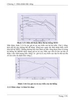
In the following illustration, files A and C contain
‘timescale
directives that set the software tool’s time units and time precision
for the code that follows the directives. File B, however, does not
contain a
‘timescale directive.
If the source files are read in the order of File A then B and then C,
the
‘timescale directive that is in effect when module B is com-
piled is 1 nanosecond units with 1 nanosecond precision. Therefore,
the delay of 5 in module B represents a delay of 5 nanoseconds.
mu
lti
p
l
e
‘timescale
directives
th
e
‘ti
mesca
l
e
directive is file
order dependent
‘timescale 1ns/1ns
module A ( );
nand #3 ( );
endmodule
File A
compilation order
module B ( );
nand #5 ( );
endmodule
File B
‘timescale 1ms/1ms
module C ( );
nand #2 ( );
endmodule
File C
Module B delays are in nanoseconds
30 SystemVerilog for Design
If the source files are read in by a compiler in a different order,
however, the effects of the compiler directives could be different.
The illustration below shows the file order as A then C and then B.
In this case, the
‘timescale directive in effect when module B is
compiled is 1 millisecond units with 1 millisecond precision.
Therefore, the delay of 5 represents 5 milliseconds. The simulation
results from this second file order will be very different than the
results of the first file order.
2.4.2 Time values with time units
SystemVerilog extends the Verilog language by allowing time units
to be specified as part of the time value.
forever #5ns clock = ~clock;
Specifying the time units as part of the time value removes all
ambiguity as to what the delay represents. The preceding example
is a 10 nanoseconds oscillator (5 ns high, 5 ns low).
The time units that are allowed are listed in the following table.
‘timescale 1ns/1ns
module A ( );
nand #3 ( );
endmodule
File A
compilation order
‘timescale 1ms/1ms
module C ( );
nand #2 ( );
endmodule
File C
module B ( );
nand #5 ( );
endmodule
File B
Module B delays are in milliseconds
ti
me un
it
s
specified as part
of the time value
Chapter 2: SystemVerilog Declaration Spaces 31
When specifying a time unit as part of the time value, there can be
no white space between the value and time unit.
#3.2ps // legal
#4.1 ps // illegal: no space allowed
2.4.3 Scope-level time unit and precision
SystemVerilog allows the time units and time precision of time val-
ues to be specified locally, as part of a module, interface or program
block, instead of as commands to the software tool (interfaces are
discussed in Chapter 10 of this book, and program blocks are pre-
sented in the companion book, SystemVerilog for Verification
1
).
In SystemVerilog, the specification of time units is further
enhanced with the keywords
timeunit and timeprecision.
These keywords are used to specify the time unit and precision
information within a module, as part of the module definition.
module chip ( );
timeunit 1ns;
timeprecision 10ps;
Table 2-1: SystemVerilog time units
Unit Description
s seconds
ms milliseconds
us microseconds
ns nanoseconds
ps picoseconds
fs femtoseconds
step
the smallest unit of time being used by the software tool
(used in SystemVerilog testbench clocking blocks)
1. Spear, Chris “SystemVerilog for Verification”, Norwell, MA: Springer 2006, 0-387-27036-1.
No space is allowed between the time value and the time unit.
NOTE
ti
meun
it
an
d
timeprecision as
part of module
definition
32 SystemVerilog for Design
endmodule
The timeunit and timeprecision keywords allow binding the
unit and precision information directly to a a module, interface or
program block, instead of being commands to the software tool.
This resolves the ambiguity and file order dependency that exist
with Verilog’s
‘timescale directive.
The units that can be specified with the
timeunit and timepre-
cision
keywords are the same as the units and precision that are
allowed with Verilog’s
‘timescale directive. These are the units
that are listed in table 2-1 on page 31, except that the special
step
unit is not allowed. As with the ‘timescale directive, the units
can be specified in multiples of 1, 10 or 100.
The specification of a module, interface or program
timeunit and
timeprecision must be the first statements within a module,
appearing immediately after the port list, and before any other dec-
larations or statements. Note that Verilog allows declarations within
the port list. This does not affect the placement of the
timeunit
and timeprecision statements. These statements must still come
immediately after the module declaration. For example:
module adder (input wire [63:0] a, b,
output reg [63:0] sum,
output reg carry);
timeunit 1ns;
timeprecision 10ps;
endmodule
2.4.4 Compilation-unit time units and precision
The timeunit and/or the timeprecision declaration can be
specified in the compilation-unit scope (described earlier in this
chapter, in section 2.2 on page 14). The declarations must come
before any other declarations. A
timeunit or timeprecision
The timeunit and timeprecision statements must be
specified immediately after the module, interface, or program
declaration, before any other declarations or statements.
NOTE
ti
meun
it
an
d
timeprecision
must be first
ex
t
erna
lti
meun
it
and
timeprecision
Chapter 2: SystemVerilog Declaration Spaces 33
declaration in the compilation-unit scope applies to all modules,
program blocks and interfaces that do not have a local
timeunit or
timeprecision declaration, and which were not compiled with
the Verilog
‘timescale directive in effect.
At most, one
timeunit value and one timeprecision value can
be specified in the compilation-unit scope. There can be more than
one
timeunit or timeprecision statements in the compilation-
unit scope, as long as all statements have the same value.
Time unit and precision search order
With SystemVerilog, the time unit and precision of a time value can
be specified in multiple places. SystemVerilog defines a specific
search order to determine a time value’s time unit and precision:
• If specified, use the time unit specified as part of the time value.
• Else, if specified, use the local time unit and precision specified
in the module, interface or program block.
• Else, if the module or interface declaration is nested within
another module or interface, use the time unit and precision in
use by the parent module or interface. Nested module declara-
tions are discussed in Chapter 9 and interfaces are discussed in
Chapter 10.
• Else, if specified, use the
`timescale time unit and precision in
effect when the module was compiled.
• Else, if specified, use the time unit and precision defined in the
compilation-unit scope.
• Else, use the simulator’s default time unit and precision.
This search order allows models using the SystemVerilog exten-
sions to be fully backward compatible with models written for Ver-
ilog.
The following example illustrates a mixture of delays with time
units,
timeunit and timeprecision declarations at both the
module and compilation-unit scope levels, and
‘timescale com-
piler directives. The comments indicate which declaration takes
precedence.
ti
me un
it
an
d
precision search
order
b
ac
k
war
d
compatibility
34 SystemVerilog for Design
Example 2-9: Mixed declarations of time units and precision (not synthesizable)
timeunit 1ns; // external time unit and precision
timeprecision 1ns;
module my_chip ( );
timeprecision 1ps; // local precision (priority over external)
always @(posedge data_request) begin
#2.5 send_packet; // uses external units & local precision
#3.75ns check_crc; // specific units take precedence
end
task send_packet();
endtask
task check_crc();
endtask
endmodule
`timescale 1ps/1ps // directive takes precedence over external
module FSM ( );
timeunit 1ns; // local units take priority over directive
always @(State) begin
#1.2 case (State) // uses local units & timescale precision
WAITE: #20ps ; // specific units take precedence
end
endmodule
2.5 Summary
This chapter has introduced SystemVerilog packages and the $unit
declaration space. Packages provide a well-defined declaration
space where user-defined types, tasks, functions and constants can
be defined. The definitions in a package can be imported into any
number of design blocks. Specific package items can be imported,
or the package definitions can be added to a design block’s search
path using a wildcard import.
Chapter 2: SystemVerilog Declaration Spaces 35
The $unit declaration space provides a quasi global declaration
space. Any definitions not contained within a design block, test-
bench block or package falls into the $unit compilation-unit space.
Care must be taken when using $unit to avoid file order dependen-
cies and differences between separate file compilation and multi-
file compilation. This chapter provided coding guidelines for the
proper usage of the $unit compilation-unit space.
SystemVerilog also allows local variables to be defined in unnamed
begin end blocks. This simplifies declaring local variables, and
also hides the local variable from outside the block. Local variables
in unnamed blocks are protected from being read or modified from
code that is not part of the block.
SystemVerilog also enhances how simulation time units and preci-
sion are specified. These enhancements eliminate the file order
dependencies of Verilog’s
‘timescale directive.
Chapter 3
SystemVerilog Literal Values
and Built-in Data Types
E
3-0:
PLE 3-0:
R
E 3-0.
ystemVerilog extends Verilog’s built-in variable types, and
enhances how literal values can be specified. This chapter
explains these enhancements and offers recommendations on
proper usage. A number of small examples illustrate these enhance-
ments in context. Subsequent chapters contain other examples that
utilize SystemVerilog’s enhanced variable types and literal values.
The next chapter covers another important enhancement to variable
types, user-defined types.
The enhancements presented in this chapter include:
• Enhanced literal values
•
‘define text substitution enhancements
• Time values
• New variable types
• Signed and unsigned types
• Variable initialization
• Static and automatic variables
• Casting
• Constants
S
38 SystemVerilog for Design
3.1 Enhanced literal value assignments
In the Verilog language, a vector can be easily filled with all zeros,
all Xs (unknown), or all Zs (high-impedance).
parameter SIZE = 64;
reg [SIZE-1:0] data;
data = 0; // fills all bits of data with zero
data = 'bz; // fills all bits of data with Z
data = 'bx; // fills all bits of data with X
Each of the assignments in the example above is scalable. If the
SIZE parameter is redefined, perhaps to 128, the assignments will
automatically expand to fill the new size of
data. However, Ver-
ilog does not provide a convenient mechanism to fill a vector with
all ones. To specify a literal value with all bits set to one, a fixed
size must be specified. For example:
data=64'hFFFFFFFFFFFFFFFF;
This last example is not scalable. If the SIZE constant is redefined
to a larger size, such as 128, the literal value must be manually
changed to reflect the new bit size of
data. In order to make an
assignment of all ones scalable, Verilog designers have had to learn
coding tricks, such as using some type of operation to fill a vector
with all ones, instead of specifying a literal value. The next two
examples illustrate using a ones complement operator and a two’s
complement operator to fill a vector with all ones:
data = ~0; // one's complement operation
data = -1; // two's complement operation
SystemVerilog enhances assignments of a literal value in two ways.
First, a simpler syntax is added, that allows specifying the fill value
without having to specify a radix of binary, octal or hexadecimal.
Secondly, the fill value can also be a logic 1. The syntax is to spec-
ify the value with which to fill each bit, preceded by an apostrophe
(
' ), which is sometimes referred to as a “tick”. Thus:
•
'0 fills all bits on the left-hand side with 0
•
'1 fills all bits on the left-hand side with 1
•
'z or 'Z fills all bits on the left-hand side with z
filli
ng a vec
t
or
with a literal
value
spec
i
a
llit
era
l
value for filling a
vector
Chapter 3: SystemVerilog Literal Values and Built-in Data Types 39
• 'x or 'X fills all bits on the left-hand side with x
Note that the apostrophe character (
' ) is not the same as the grave
accent (
` ), which is sometimes referred to as a “back tick”.
Using SystemVerilog, a vector of any width can be filled with all
ones without hard coding the width of the value to be assigned, or
using operations.
data = '1; // fills all bits of data with 1
This enhancement to the Verilog language simplifies writing mod-
els that work with very large vector sizes. The enhancement also
makes it possible to code models that automatically scale to new
vector sizes without having to modify the logic of the model. This
automatic scaling is especially useful when using initializing vari-
ables that have parameterized vector widths.
3.2 ‘define enhancements
SystemVerilog extends the ability of Verilog’s ‘define text substi-
tution macro by allowing the macro text to include certain special
characters.
3.2.1 Macro argument substitution within strings
Verilog allows the quotation mark ( " ) to be used in a ‘define
macro, but the text within the quotation marks became a literal
string. This means that in Verilog, it is not possible to create a string
using text substitution macros where the string contains embedded
macro arguments.
In Verilog, the following example will not work as intended:
`define print(v) \
$display("variable v = %h", v)
`print(data);
In this example, the macro ‘print() will expand to:
$display("variable v = %h", data);
lit
era
l
va
l
ues
scale with the
size of the left-
hand side vector
40 SystemVerilog for Design
The intent of this text substitution example is that all occurrences of
the macro argument
v will be substituted with the actual argument
value,
data. However, since the first occurrence of v is within
quotes in the macro definition, Verilog does not substitute the first
occurrence of
v with data.
SystemVerilog allows argument substitution inside a macro text
string by preceding the quotation marks that form the string with a
grave accent (
‘ ). The example below defines a text substitution
macro that represents a complete
$display statement. The string
to be printed contains a
%h format argument. The substituted text
will contain a text string that prints a message, including the name
and logic value of the argument to the macro. The %h within the
string will be correctly interpreted as a format argument.
`define print(v) \
$display(‘"variable v = %h‘", v)
`print(data);
In this example, the macro ‘print() will expand to:
$display("variable data = %h", data);
In Verilog, quotation marks embedded within a string must be
escaped using
\" so as to not affect the quotation marks of the
outer string. The following Verilog example embeds quotation
marks within a print message.
$display("variable \"data\" = %h", data);
When a string is part of a text substitution macro that contains vari-
able substitution, it is not enough to use
\" to escape the embedded
quotation marks. Instead,
‘\‘" must be used. For example:
`define print(v) \
$display(‘"variable ‘\‘"v‘\‘" = %h‘", v)
`print(data);
In this example, the macro ‘print() will expand to:
$display("variable \"data\" = %h", data);
‘" a
ll
ows macro
argument
substitution
within strings
‘\‘" a
ll
ows an
escaped quote
in a macro text
string containing
argument
substitution
Chapter 3: SystemVerilog Literal Values and Built-in Data Types 41
3.2.2 Constructing identifier names from macros
Using Verilog ‘define, it is not possible to construct an identifier
name by concatenating two or more text macros together. The prob-
lem is that there will always be a white space between each portion
of the constructed identifier name.
SystemVerilog provides a way to delimit an identifier name without
introducing a white space, using two consecutive grave accent
marks, i.e.
‘‘. This allows two or more names to be concatenated
together to form a new name.
One application for
‘‘ is to simplify creating source code where a
set of similar names are needed several times, and an array cannot
be used. In the following example, a 2-state bit variable and a
wand net need to be defined with similar names, and a continuous
assignment of the variable to the net. The variable allows local pro-
cedural assignments, and the net allows wired logic assignments
from multiple drivers, where one of the drivers is the 2-state vari-
able: The
bit type is discussed in more detail later in this chapter.
In brief, the
bit type is similar to the Verilog reg type, but bit
variables only store 2-state values, whereas reg stores 4-state val-
ues.
In source code without text substitution, these declarations might
be:
bit d00_bit; wand d00_net = d00_bit;
bit d01_bit; wand d01_net = d01_bit;
// repeat 60 more times, for each bit
bit d62_bit; wand d62_net = d62_bit;
bit d63_bit; wand d63_net = d63_bit;
Using the SystemVerilog enhancements to ‘define, these declara-
tions can be simplified as:
‘define TWO_STATE_NET(name) bit name‘‘_bit; \
wand name‘‘_net = name‘‘_bit;
‘TWO_STATE_NET(d00)
‘TWO_STATE_NET(d01)
‘TWO_STATE_NET(d62)
‘TWO_STATE_NET(d63)
‘‘ serves as a
delimiter without
a space in the
macro text
42 SystemVerilog for Design
3.3 SystemVerilog variables
3.3.1 Object types and data types
Verilog data types
The Verilog language has hardware-centric variable types and net
types. These types have special simulation and synthesis semantics
to represent the behavior of actual connections in a chip or system.
• The Verilog
reg, integer and time variables have 4 logic val-
ues for each bit: 0, 1, Z and X.
• The Verilog
wire, wor, wand, and other net types have 120 val-
ues for each bit (4-state logic plus multiple strength levels) and
special wired logic resolution functions.
SystemVerilog data types
Verilog does not clearly distinguish between signal types, and the
value set the signals can store or transfer. In Verilog, all nets and
variables use 4-state values, so a clear distinction is not necessary.
To provide more flexibility in variable and net types and the values
that these types can store or transfer, the SystemVerilog standard
defines that signals in a design have both a type and a data type.
Type indicates if the signal is a net or variable. SystemVerilog uses
all the Verilog variable types, such as
reg and integer, plus adds
several more variable types, such as
byte and int. SystemVerilog
does not add any extensions to the Verilog net types.
Data type indicates the value system of the net or variable, which is
0 or 1 for 2-state data types, and 0, 1, Z or X for 4-state data types.
The SystemVerilog keyword
bit defines that an object is a 2-state
data type. The SystemVerilog keyword
logic defines that an
object is a 4-state data type. In the SystemVerilog-2005 standard,
variable types can be either 2-state or 4-state data types, where as
net types can only be 4-state data types.
V
er
il
og
’
s
hardware
types
d
a
t
a
declarations
have a type and
a data type
“t
ype
”d
e
fi
nes
if
data is a net or
variable
“d
a
t
a
t
ype
”
defines if data is
2-state or
4-state