COMPUTER NUMERICAL CONTROL PROGRAMMING BASICS phần 3 pdf
Bạn đang xem bản rút gọn của tài liệu. Xem và tải ngay bản đầy đủ của tài liệu tại đây (474.82 KB, 10 trang )
16
merge individual axis points into a predefined tool path is built into
most of today’s MCUs. There are five methods of interpolation:
linear, circular, helical, parabolic, and cubic. All contouring controls
provide linear interpolation, and most controls are capable of both
linear and circular interpolation. Helical, parabolic, and cubic
interpolation are used by industries that manufacture parts which
have complex shapes, such as aerospace parts and dies for car
bodies.
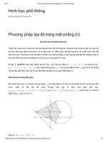
Linear Interpolation
Linear Interpolation
consists of any programmed points linked
together by straight lines, whether the points are close together or
far apart (Fig. 11). Curves can be produced with linear interpola-
tion by breaking them into short, straight-line segments. This
method has limitations, because a very large number of points
would have to be programmed to describe the curve in order to
produce a contour shape.
A contour programmed in linear interpolation requires the coordi-
nate positions (XY positions in two-axis work) for the start and
finish of each line segment. Therefore, the end point of one line or
segment becomes the start point for the next segment, and so on,
throughout the entire program.
Fig. 11 An example of two-axis linear interpolation. (Kelmar Associates)
17
Fig. 12 For two-dimensional circular interpolation the MCU must be supplied with the XY axis,
radius, start point, end point, and direction of cut. (Kelmar Associates)
Programming Format
Word address is the most common programming format used for
CNC programming systems. This format contains a large number
of different codes (preparatory and miscellaneous) that transfers
program information from the part print to machine servos, relays,
micro-switches, etc., to manufacture a part. These codes, which
conform to EIA (Electronic Industries Association) standards, are
in a logical sequence called a
block of information
. Each block
should contain enough information to perform one machining
operation.
Word Address Format
Every program for any part to be machined, must be put in a
Circular Interpolation
The development of MCUs capable of
circular interpolation
has
greatly simplified the process of programming arcs and circles. To
program an arc (Fig. 12), the MCU requires only the coordinate
positions (the XY axes) of the circle center, the radius of the circle,
the start point and end point of the arc being cut, and the direction
in which the arc is to be cut (clockwise or counterclockwise) See
Fig. 12. The information required may vary with different MCUs.
18
format that the machine control unit can understand. The format
used on any CNC machine is built in by the machine tool builder
and is based on the type of control unit on the machine. A vari-
able-block format which uses words (letters) is most commonly
used. Each instruction word consists of an address character,
such as X, Y, Z, G, M, or S. Numerical data follows this address
character to identify a specific function such as the distance, feed
rate, or speed value.
The address code G90 in a program, tells the control that all
measurements are in the absolute mode. The code G91, tells the
control that measurements are in the incremental mode.
Codes
The most common codes used when programming CNC ma-
chines tools are
G-codes
(preparatory functions), and
M codes
(miscellaneous functions). Other codes such as F, S, D, and T are
used for machine functions such as feed, speed, cutter diameter
offset, tool number, etc.
G-codes are sometimes called cycle codes because they refer to
some action occurring on the X, Y, and/or Z axis of a machine tool,
Fig. 13.
The G-codes are grouped into categories such as Group 01,
containing codes G00, G01, G02, G03. which cause some move-
ment of the machine table or head. Group 03 includes either
absolute or incremental programming, while Group 09 deals with
canned cycles.
A G00 code rapidly positions the cutting tool while it is above the
workpiece from one point to another point on a job. During the
rapid traverse movement, either the X or Y axis can be moved
individually or both axes can be moved at the same time. Although
the rate of rapid travel varies from machine to machine, it ranges
between 200 and 800 in./min (5 and 20 m/min).
19
Fig. 13 The functions of a few common G-codes. (Deckel Maho, Inc.)
The G01, G02, and G03 codes move the axes at a controlled
feedrate.
• G01 is used for straight-line movement (linear interpolation).
• G02 (clockwise) and G03 (counterclockwise) are used for arcs
and circles (circular interpolation).
G00
RAPID TRAVERSE
G01
LINEAR INTERPOLATION
(STRAIGHT LINE MOVEMENT)
G02
CIRCULAR INTERPOLATION
(CLOCKWISE)
G03
CIRCULAR INTERPOLATION
(COUNTERCLOCKWISE)
20
Group Code Function
01 G00 Rapid positioning
01 G01 Linear interpolation
01 G02 Circular interpolation clockwise (CW)
01 G03 Circular interpolation counterclockwise (CCW)
06 G20* Inch input (in.)
06 G21* Metric input (mm)
G24 Radius programming (**)
00 G28 Return to reference point
00 G29 Return from reference point
G32 Thread cutting (**)
07 G40 Cutter compensation cancel
07 G41 Cutter compensation left
07 G42 Cutter compensation right
08 G43 Tool length compensation positive (+) direction
08 G44 Tool length compensation minus (-) direction
08 G49 Tool length compensation cancel
G84 Canned turning cycle (**)
03 G90 Absolute programming
03 G91 Incremental programming
(*) - on some machines and controls, these may be G70 (inch) and
G71 (metric)
(**) - refers only to CNC lathes and turning centers.
Fig. 14 Some of the most common G-codes used in CNC programming.
M or miscellaneous codes are used to either turn ON or OFF
different functions which control certain machine tool operations,
Fig. 15.
M-codes are not grouped into categories, although several codes
may control the same type of operations such as M03, M04, and
M05 which control the machine tool spindle.
• M03 turns the spindle on clockwise
• M04 turns the spindle on counterclockwise
• M05 turns the spindle off
21
Fig. 15 The functions of a few common M-codes. (Deckel Maho, Inc.)
M03
DIRECTION OF ROTATION
(CLOCKWISE)
M04
DIRECTION OF ROTATION
(COUNTERCLOCKWISE)
M06
TOOL CHANGE WITH
AUTOMATIC RETRACTION
M30
END OF PROGRAM
AND
RETURN TO BEGINNING
OF PROGRAM
22
Code Function
M00 Program stop
M02 End of program
M03 Spindle start (forward CW)
M04 Spindle start (reverse CCW)
M05 Spindle stop
M06 Tool change
M08 Coolant on
M09 Coolant off
M10 Chuck - clamping (**)
M11 Chuck - unclamping (**)
M12 Tailstock spindle out (**)
M13 Tailstock spindle in (**)
M17 Toolpost rotation normal (**)
M18 Toolpost rotation reverse (**)
M30 End of tape and rewind
M98 Transfer to subprogram
M99 End of subprogram
(**) - refers only to CNC lathes and turning centers.
Fig. 16 Some of the most common M-codes used in CNC programming.
Block of Information
CNC information is generally programmed in blocks of five words.
Each word conforms to the EIA standards and they are written on
a horizontal line. If five complete words are not included in each
block, the machine control unit (MCU) will not recognize the
information, therefore the control unit will not be activated.
Using the example shown in Fig. 17 , the five words are as fol-
lows:
N001 represents the sequence number of the operation.
G01 represents linear interpolation
X12345 will move the table 1.2345 in. in a positive direction
along the X axis.
Y06789 will move the table 0.6789 in. along the Y axis.
M03 Spindle on CW.
23
Fig. 17 A complete block of information consists of five words. (Kelmar Associates)
Programming for Positioning
Before starting to program a job, it is important to become familiar
with the part to be produced. From the engineering drawings, the
programmer should be capable of planning the machining se-
quences required to produce the part. Visual concepts must be
put into a written manuscript as the first step in developing a part
program, Fig. 18. It is the part program that will be sent to the
machine control unit by the computer, tape, diskette, or other input
media.
The programmer must first establish a reference point for aligning
the workpiece and the machine tool for programming purposes.
The manuscript must include this along with the types of cutting
tools and work-holding devices required, and where they are to be
located.
24
Fig. 18 The first step in producing a CNC program is to take the information from the print and
produce a program manuscript. (Deckel Maho, Inc.)
Dimensioning Guidelines
The system of rectangular coordinates is very important to the
successful operation of CNC machines. Certain guidelines should
be observed when dimensioning parts for CNC machining. The
following guidelines will insure that the dimensioning language
means exactly the same thing to the design engineer, the techni-
cian, the programmer, and the machine operator.
1. Define part surfaces from three perpendicular reference
planes.
2. Establish reference planes along part surfaces which are
parallel to the machine axes.
3. Dimension from a specific point on the part surface.
25
4. Dimension the part clearly so that its shape can be understood
without making mathematical calculations or guesses.
5. Define the part so that a computer numerical control cutter
path can be easily programmed.
Machine Zero Point
The machine zero point can be set by three methods—by the
operator, manually by a programmed absolute zero shift, or by
work coordinates, to suit the holding fixture or the part to be
machined.
MANUAL SETTING - The operator can use the MCU controls to
locate the spindle over the desired part zero and then set the X
and Y coordinate registers on the console to zero.
Fig. 19 The relationship between the part zero and the machine system of coordinates.
(Deckel Maho, Inc.)
Stored zero shifts (G54 G59)
Programmed zero shift (G92)
R = Reference point (maximum travel of machine)
M = Machine zero point (X0,Y0,Z0) of machine coordinate system.
W = Part zero point workpiece coordinate system.
Under G54 G59 the actual machine coordinates of part
zero are stored in the stored zero offsets memory and
activated in the part program.
Under G92 the actual machine coordinates are inserted and
used on the G92 line of the part program.