DESIGN OF MASONRY STRUCTURES Part 2 pptx
Bạn đang xem bản rút gọn của tài liệu. Xem và tải ngay bản đầy đủ của tài liệu tại đây (724.67 KB, 22 trang )
m intervals as a general rule. However, the length of the panel without
movement joint should not exceed twice the height.
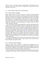
Some indication of reversible or irreversible movement of various
building materials is shown in Table 2.5.
The EC6 gives guidance for the design values of dimensional changes
for unreinforced masonry, which are given in Chapter 4 (section 4.4).
2.2.7 Soluble salts
(a) Efflorescence
All clay bricks contain soluble salts to some extent. The salt can also find
its way from mortar or soil or by contamination of brick by foreign
agents. In a new building when the brickwork dries out owing to
evaporation of water, the dissolved salts normally appear as a white
deposit termed ‘efflorescence’ on the surface of bricks. Sometimes the
colour may be yellow or pale green because of the presence of vanadium
or chromium. The texture may vary from light and fluffy to hard and
glassy. Efflorescence is caused by sulphates of sodium, potassium,
magnesium and calcium; not all of these may be present in a particular
case. Efflorescence can take place on drying out brickwork after
construction or subsequently if it is allowed to become very wet. By and
large, efflorescence does not normally result in decay, but in the United
Kingdom, magnesium sulphate or sodium sulphate may cause
disruption due to crystallization. Abnormal amounts of sodium
sulphate, constituting more than 3% by weight of a brick, will cause
disruption of its surface. Brick specimens showing efflorescence in the
‘heavy’ category are not considered to comply with BS 3921.
(b) Sulphate attack
Sulphates slowly react in the presence of water with tricalcium
aluminate, which is one of the constituents of Portland cement and
Table 2.5 Moisture movement in different building materials
©2004 Taylor & Francis
hydraulic lime. If water containing dissolved sulphate from clay bricks
or aggregates reaches the mortar, this reaction takes place, causing
mortar to crack and spall and thus resulting in the disintegration of the
masonry. Sulphate attack is only possible if the masonry is exposed to
very long and persistent wet conditions. Chimneys, parapets and earth-
retaining walls which have not been properly protected from excessive
dampness may be vulnerable to sulphate attack. In general, it is
advisable to keep walls as dry as possible. In conditions of severe
exposure to rain, bricks (L) or sulphate-resistant cement should be used.
The resistance of mortar against sulphate attack can be increased by
specifying a fairly rich mix, i.e. stronger than grade (iii) mortar (1:1:6) or
replacing lime with a plasticizer. Calcium silicate and concrete units do
not contain significant amounts of sulphate compared to clay bricks.
However, concrete bricks of minimum 30 N/mm
2
strength should be
used in mortar for earth-retaining walls, cills and copings.
2.2.8 Fire resistance
Clay bricks are subjected to very much higher temperatures during firing
than they are likely to be exposed to in a building fire. As a result, they
possess excellent fire resistance properties. Calcium silicate bricks have
similar fire resistance properties to clay bricks. Concrete bricks and
blocks have 30 min to 6 h notional fire resistance depending on the
thickness of the wall.
2.3 MORTAR
The second component in brickwork is mortar, which for loadbearing
brickwork should be a cement:lime:sand mix in one of the designations
shown in Table 2.6. For low-strength bricks a weaker mortar, 1:2:9 mix by
volume, may be appropriate. For reinforced and prestressed brickwork,
mortar weaker than grade (ii)
is not recommended.
2.3.1 Function and requirement of mortar
In deciding the type of mortar the properties needing to be considered are:
• Development of early strength.
• Workability, i.e. ability to spread easily.
• Water retentivity, i.e. the ability of mortar to retain water against the
suction of brick. (If water is not retained and is extracted quickly by a
high-absorptive brick, there will be insufficient water left in the
mortar joint for hydration of the cement, resulting in poor bond
between brick and mortar.)
©2004 Taylor & Francis
• Proper development of bond with the brick.
• Resistance to cracking and rain penetration.
• Resistance to frost and chemical attack, e.g. by soluble sulphate.
• Immediate and long-term appearance.
2.3.2 Cement
The various types of cement used for mortar are as follows.
(a) Portland cement
Ordinary Portland cement and rapid-hardening cement should conform
to a standard such as BS 12. Rapid-hardening cement may be used
instead of ordinary Portland cement where higher early strength is
required; otherwise its properties are similar. Sulphate-resistant cement
should be used in situations where the brickwork is expected to remain
wet for prolonged periods or where it is susceptible to sulphate attack,
e.g. in brickwork in contact with sulphate-bearing soil.
(b) Masonry cement
This is a mixture of approximately 75% ordinary Portland cement, an inert
mineral filler and an air-entraining agent. The mineral filler is used to reduce
the cement content, and the air-entraining agent is added to improve the
workability. Mortar made from masonry cement will have lower strength
compared to a normal cement mortar of similar mix. The other properties
of the mortar made from the masonry cement are intermediate between
cement:lime:sand mortar and plasticized cement:sand mortar.
2.4 LIME: NON-HYDRAULIC OR SEMI-HYDRAULIC LIME
Lime is added to cement mortar to improve the workability, water
retention and bonding properties. The water retentivity property of lime
is particularly important in situations where dry bricks might remove a
considerable amount of water from the mortar, thus leaving less than
required for the hydration of the cement. Two types of lime are used,
non-hydraulic or semi-hydraulic, as one of the constituents of mortar for
brickwork. These limes are differentiated by the process whereby they
harden and develop their strengths. Non-hydraulic lime initially stiffens
because of loss of water by evaporation or suction by bricks, and
eventually hardens because of slow carbonation, i.e. absorption of
carbon dioxide from the air to change calcium hydroxide to calcium
carbonate. Semi-hydraulic lime will harden in wet conditions as a result
of the presence of small quantities of compounds of silica and alumina. It
©2004 Taylor & Francis
hardens owing to chemical reaction with water rather than atmospheric
action. In the United Kingdom, the lime used for mortar must conform to
BS 890.
2.5 SAND
The sand for mortar must be clean, sharp, and free from salt and organic
contamination. Most natural sand contains a small quantity of silt or
clay. A small quantity of silt improves the workability. Loam or clay is
moisture-sensitive and in large quantities causes shrinkage of mortar.
Marine and estuarine sand should not be used unless washed completely
to remove magnesium and sodium chloride salts which are deliquescent
Fig. 2.4 Grading limits of mortar sand (BS 1200).
©2004 Taylor & Francis
and attract moisture. Specifications of sand used for mortar, such as BS
1200, prescribe grading limits for the particle size distribution. The limits
given in BS 1200 are as shown in Fig. 2.4, which identifies two types of
sand:sand type S and sand type G. Both types of sand will produce
satisfactory mortars. However, the grading of sand type G, which falls
between the lower limits of sand S and sand G, may require slightly more
cement for a particular grade of mortar to satisfy the strength
requirement envisaged in BS 5628 (refer to Table 2.6).
2.6 WATER
Mixing water for mortar should be clean and free from contaminants either
dissolved or in suspension. Ordinary drinking water will be suitable.
2.7 PLASTICIZED PORTLAND CEMENT MORTAR
To reduce the cement content and to improve the workability, plasticizer,
which entrains air, may be used. Plasticized mortars have poor water
retention properties and develop poor bond with highly absorptive
bricks. Excessive use of plasticizer will have a detrimental effect on
strength, and hence manufacturers’ instructions must be strictly
followed. Plasticizer must comply with the requirements of BS 4887.
2.8 USE OF PIGMENTS
On occasion, coloured mortar is required for architectural reasons. Such
pigments should be used strictly in accordance with the instructions of
the manufacturer since excessive amounts of pigment will reduce the
compressive strength of mortar and interface bond strength. The
quantity of pigment should not be more than 10% of the weight of the
cement. In the case of carbon black it should not be more than 3%.
2.9 FROST INHIBITORS
Calcium chloride or preparations based on calcium chloride should not
be used, since they attract water and cause dampness in a wall, resulting
in corrosion of wall ties and efflorescence.
2.10 PROPORTIONING AND STRENGTH
The constituents of mortar are mixed by volume. The proportions of
material and strength are given in Table 2.6. For loadbearing brickwork
the mortar must be gauged properly by the use of gauging boxes and
preferably should be weigh-batched.
©2004 Taylor & Francis
Recent research (Fig. 2.5) has shown that the water/cement ratio is the
most important factor which affects the compressive strength of grades I,
II and III mortars. In principle, therefore, it would be advisable for the
structural engineer to specify the water/cement ratio for mortar to be
used for structural brickwork; but, in practice, the water/cement ratio
for a given mix will be determined by workability. There are various
laboratory tests for measuring the consistency of mortar, and these have
been related to workability. Thus in the United Kingdom, a dropping ball
test is used in which an acrylic ball of 10 mm diameter is dropped on to
the surface of a sample of mortar from a height of 250 mm. A ball
penetration of 10 mm is associated with satisfactory workability. The test
is, however, not used on site, and it is generally left to the bricklayer to
adjust the water content to achieve optimum workability. This in fact
achieves a reasonably consistent water/cement ratio which varies from
one mix to another. The water/cement ratio for 10mm ball penetration,
representing satisfactory workability, has been indicated in Fig. 2.5 for
the three usual mortar mixes.
It is important that the practice of adding water to partly set mortar to
restore workability (known as ‘knocking up’ the mix) should be prevented.
2.11 CHOICE OF UNIT AND MORTAR
Table 2.7 shows the recommended minimum quality of clay or calcium
silicate or concrete bricks/blocks and mortar grades which should be
used in various situations from the point of view of durability.
2.12 WALL TIES
In the United Kingdom, external cavity walls are used for environmental
reasons. The two skins of the wall are tied together to provide some
degree of interaction. Wall ties for cavity walls should be galvanized
mild steel or stainless steel and must comply to BS 1243. Three types of
ties (Fig. 2.6) are used for cavity walls.
• Vertical twist type made from 20 mm wide, 3.2 to 4.83 mm thick metal
strip
• ‘Butterfly’—made from 3.15 mm wire
• Double-triangle type—made from 4.5 mm wire.
For loadbearing masonry vertical twist type ties should be used for
maximum co-action. For a low-rise building, or a situation where large
differential movement is expected or for reason of sound insulation,
more flexible ties should be selected. In certain cases where large
differential movements have to be accommodated, special ties or fixings
have to be used (see Chapter 13). In specially unfavourable situations
©2004 Taylor & Francis
Table 2.7 (Contd)
©2004 Taylor & Francis
©2004 Taylor & Francis
Table 2.7 (Contd)
©2004 Taylor & Francis
©2004 Taylor & Francis
Table 2.7 (Contd)
©2004 Taylor & Francis
©2004 Taylor & Francis
Table 2.7 (Contd)
©2004 Taylor & Francis
©2004 Taylor & Francis
Table 2.7 (Contd)
©2004 Taylor & Francis
©2004 Taylor & Francis
The maximum size of the aggregate can be increased depending on the
size and configuration of the void to be filled with concrete. In some
cases it would be possible to use concrete design mix as specified in BS
5328 for reinforced and prestressed masonry. In reinforced and
prestressed masonry, the bricks or blocks coming in contact with concrete
will absorb water from the mix depending on its water retentivity
property, and hence maximum free water/cement ratio used in BS 8110
may not be applicable. In order to compensate for this and for free
flowing of the mix to fill the space and the void, a slump of 75 mm and
175mm for concrete mix has been recommended in BS 5628: Part 2.
In prestressed sections where tendons are placed in narrow ducts, a
neat cement or sand:cement grout having minimum compressive
strength of 17 N/mm
2
at 7 days may be used.
Table 2.8 Chloride content of mixes
Table 2.9 Characteristic tensile strength of reinforcing steel
©2004 Taylor & Francis
The mix must conform to the limit prescribed by BS 5628: Part 2 for
maximum total chloride content as in Table 2.8.
2.14 REINFORCING AND PRESTRESSING STEEL
2.14.1 Reinforcing steel
Hot-rolled or cold-worked steel bars and fabric conforming to the
relevant British Standard can be used as reinforcement. The
characteristic strengths of reinforcement are given in Table 2.9.
In situations where there is risk of contamination by chloride, solid
stainless steel or low-carbon steel coated with at least 1 mm of austenitic
stainless steel may be used.
2.14.2 Prestressing steel
Wire, strands and bars complying to BS 4486 or BS 5896 can be used for
prestressing. Seventy per cent of the characteristic breaking load is
allowed as jacking force for prestressed masonry which is less than the
75% normally allowed in prestressed concrete. If proper precautions are
taken, there is no reason why the initial jacking force cannot be taken to
75–80% of the breaking load. This has been successfully demonstrated in
a series of prestressed brick test beams at Edinburgh University.
The short-term design stress-strain curve for prestressing steel is
shown in Fig. 2.7.
Fig. 2.7 Typical short-term design stress-strain curve for normal and low-
relaxation tendons.
©2004 Taylor & Francis
3
Masonry properties
3.1 GENERAL
Structural design in masonry requires a clear understanding of the
behaviour of the composite unit-mortar material under various stress
conditions. Primarily, masonry walls are vertical loadbearing elements in
which resistance to compressive stress is the predominating factor in
design. However, walls are frequently required to resist horizontal shear
forces or lateral pressure from wind and therefore the strength of
masonry in shear and in tension must also be considered.
Current values for the design strength of masonry have been derived
on an empirical basis from tests on piers, walls and small specimens.
Whilst this has resulted in safe designs, it gives very little insight into the
behaviour of the material under stress so that more detailed discussion
on masonry strength is required.
3.2 COMPRESSIVE STRENGTH
3.2.1 Factors affecting compressive strength
The factors set out in Table 3.1 are of importance in determining the
compressive strength of masonry.
Table 3.1 Factors affecting masonry strength
©2004 Taylor & Francis
3.2.2 Unit/mortar/masonry strength relationship
A number of important points have been derived from compression tests
on masonry and associated standard tests on materials. These include,
first, that masonry loaded in uniform compression will fail either by the
development of tension cracks parallel to the axis of loading or by a kind
of shear failure along certain lines of weakness, the mode of failure
depending on whether the mortar is weak or strong relative to the units.
Secondly, it is observed that the strength of masonry in compression is
smaller than the nominal compressive strength of the units as given by a
standard compressive test. On the other hand, the masonry strength may
greatly exceed the cube crushing strength of the mortar used in it. Finally,
it has been shown that the compressive strength of masonry varies
roughly as the square root of the nominal unit crushing strength and as
the third or fourth root of the mortar cube strength.
From these observations it may be inferred that:
1. The secondary tensile stresses which cause the splitting type of failure
result from the restrained deformation of the mortar in the bed joints
of the masonry.
2. The apparent crushing strength of the unit in a standard test is not a
direct measure of the strength of the unit in the masonry, since the
mode of failure is different in the two situations.
3. Mortar withstands higher compressive stresses in a brickwork bed
joint because of the lateral restraint on its deformation from the unit.
Various theories for the compressive strength of masonry have been
proposed based on equation of the lateral strains in the unit and mortar
at their interface and an assumed limiting tensile strain in the unit. Other
theories have been based on measurement of biaxial and triaxial strength
tests on materials. But in both approaches the difficulties of determining
the necessary materials properties have precluded their practical use,
and for design purposes reliance continues to be placed on empirical
relationships between unit, mortar and masonry strengths. Such
relationships are illustrated in Fig. 3.1 and are incorporated in codes of
practice, as set out in Chapter 4 for BS 5628 and Eurocode 6.
3.2.3 Some effects of unit characteristics
The apparent strength of a unit of given material increases with decrease
in height because of the restraining effect of the testing machine platens
on the lateral deformation of the unit. Also, in masonry the units have to
resist the tensile forces resulting from restraint of the lateral strains in the
mortar. Thus for given materials and joint thickness, the greater the
height of the unit the greater the resistance to these forces and the greater
©2004 Taylor & Francis
the resulting masonry strength will be different from that of masonry in
which the units are laid on their normal bed faces. The masonry strength
will also depend on the type of unit: a highly perforated unit is likely to
be relatively weak when compressed in a direction parallel to its length
and thus result in a correspondingly lower masonry strength. This is
illustrated in Table 3.2 which gives some results for brickwork built with
various types of bricks. From this table it can be seen that, although there
is a substantial reduction in brickwork strength when built and stressed
in directions other than normal, this is not proportional to the brick
strength when the latter is compressed in the corresponding direction.
No general rule can be given relating brickwork to brick strength when
compressed with the units laid on edge or on end.
Special considerations apply to masonry built with hollow blocks in
which the cores may be unfilled or filled with concrete. In the former
case the mortar joint may cover the whole of the bed face of the block
(full-bedded) or only the outer shells (shell-bedded).
The strength of full-bedded blocks is taken to be that of the maximum
test load divided by the gross area of the unit and the masonry strength is
Fig. 3.2 Effect of joint thickness on brickwork strength.
©2004 Taylor & Francis
been carried out with a view to establishing limiting stresses for use in
design. Typical results are shown in Fig. 3.3. It is found that there is a
Coulomb type of relationship between shear strength and
precompression, i.e. there is an initial shear resistance dependent on
adhesion between the units and mortar augmented by a frictional
component proportional to the precompression. This may be expressed
by the formula:
(3.2)
where
τ
0
is the shear strength at zero precompression, µ is an apparent
coefficient of friction and
σ
c
is the vertical compressive stress.
This relationship holds up to a certain limiting value of the vertical
compression, beyond which the joint failure represented by the Coulomb
equation is replaced by cracking through the units. For clay bricks this
limit is about 2.0 N/mm
2
. The shear strength depends on the mortar
strength and for units with a compressive strength between 20 and 50 N/
mm
2
set in strong mortar the value of t
0
will be approximately 0.3
N/mm
2
and 0.2 N/mm
2
for medium strength (1:1:6) mortar. The average
value of µ is 0.4–0.6.
The shear stresses quoted above are average values for walls having a
height-to-length ratio of 1.0 or more and the strength of a wall is
calculated on the plan area of the wall in the plane of the shear force.
Fig. 3.3 Typical relationship between shear strength of brickwork and vertical
precompression from test results.
©2004 Taylor & Francis