DESIGN OF MASONRY STRUCTURES Part 4 ppsx
Bạn đang xem bản rút gọn của tài liệu. Xem và tải ngay bản đầy đủ của tài liệu tại đây (415.62 KB, 20 trang )
(f) Deformation properties of masonry
It is stated that the stress-strain relationship for masonry is parabolic in
form but may for design purposes be assumed as an approximation to be
rectangular or parabolic-rectangular. The latter is a borrowing from
reinforced concrete practice and may not be applicable to all kinds of
masonry.
The modulus of elasticity to be assumed is the secant modulus at the
serviceability limit, i.e. at one-third of the maximum load. Where the results
of tests in accordance with the relevant European standard are not available
E under service conditions and for use in structural analysis may be taken
as 1000f
k
. It is further recommended that the E value should be multiplied
by a factor of 0.6 when used in determining the serviceability limit state. A
reduced E value is also to be adopted in relation to long-term loads. This
may be estimated with reference to creep data.
In the absence of more precise data, the shear modulus may be
assumed to be 40% of E.
Table 4.7 Values of f
vk0
and limiting values of f
vk
for general-purpose mortar (EC6)
a
©2004 Taylor & Francis
(g) Creep, shrinkage and thermal expansion
A table is provided of approximate values to be used in the calculation of
creep, shrinkage and thermal effects. However, as may be seen from
Table 4.8 these values are given in terms of rather wide ranges so that it is
difficult to apply them in particular cases in the absence of test results for
the materials being used.
4.4.4 Section 4: design of masonry
(a) General stability
Initial provisions of this section call for overall stability of the structure to
be considered. The plan layout of the building and the interconnection of
Table 4.8 Deformation properties of unreinforced masonry made with
generalpurpose mortar (EC6).
©2004 Taylor & Francis
elements must be such as to prevent sway. The possible effects of
imperfections should be allowed for by assuming that the structure is
inclined at an angle of
to the vertical where h
tot
is the total
height of the building. One designer must, unambiguously, be
responsible for ensuring overall stability.
(b) Accidental damage
Buildings are required to be designed in such a way that there is a
‘reasonable probability’ that they will not collapse catastrophically under
the effect of misuse or accident and that the extent of damage will not be
disproportionate to the cause. This is to be achieved by considering the
removal of essential loadbearing members or designing them to resist the
effects of accidental actions. However, no specific rules relating to these
requirements are given.
(c) Design of structural members
The design of members has to be such that no damage is caused to
facings, finishes, etc., but it may be assumed that the serviceability limit
state is satisfied if the ultimate limit state is verified. It is also required
that the stability of the structure or of individual walls is ensured during
construction.
Subject to detailed provisions relating to the type of construction, the
design vertical load resistance per unit length, N
Rd
, of an unreinforced
masonry wall is calculated from the following expression:
(4.12)
where Φ
i,m
is a capacity reduction factor allowing for the effects of
slenderness and eccentricity (Φ
i
applies to the top and bottom of the wall;
Φ
m
applies to the mid-height and is obtained from the graph shown in
Fig. 4.6), t is the thickness of the wall, f
k
is the characteristic compressive
strength of the masonry and
␥
m
is the partial safety factor for the
material.
The capacity reduction factor Φ
i
is given by:
(4.13)
where e
i
is the eccentricity at the top or bottom of the wall calculated
from
(4.14)
where M
i
and N
i
are respectively the design bending moment and
vertical load at the top or bottom of the wall and e
hi
and e
a
are
©2004 Taylor & Francis
Rules are given for the assessment of the effective height of a wall. In
general, walls restrained top and bottom by reinforced concrete slabs are
assumed to have an effective height of 0.75×actual height. If similarly
restrained by timber floors the effective height is equal to the actual
height. Formulae are given for making allowance for restraint on vertical
edges where this is known to be effective. Allowance may have to be
made for the presence of openings, chases and recesses in walls.
The effective thickness of a wall of ‘solid’ construction is equal to the
actual thickness whilst that of a cavity wall is
(4.18)
where t
1
and t
2
are the thicknesses of the leaves. Some qualifications of
this rule are applicable if only one leaf is loaded.
The out-of-plane eccentricity of the loading on a wall is to be assessed
having regard to the material properties and the principles of mechanics.
A possible, simplified method for doing this is given in an Annex, but
presumably any other valid method would be permissible.
An increase in the design load resistance of an unreinforced wall
subjected to concentrated loading may be allowed. For walls built with
units having a limited degree of perforation, the maximum design
compressive stress in the locality of a beam bearing should not exceed
(4.19)
where and A
ef
are as shown in Fig. 4.7.
This value should be greater than the design strength f
k
/
␥
m
but not
greater than 1.25 times the design strength when x=0 or 1.5 times this
value when x=1.5. No increase is permitted in the case of masonry built
with perforated units or in shell-bedded masonry.
(d) Design of shear walls
Rather lengthy provisions are set out regarding the conditions which
may be assumed in the calculation of the resistance of shear walls but the
essential requirement is that the design value of the applied shear load,
V
sd
, must not exceed the design shear resistance, V
Rd
, i.e.
(4.20)
where f
vk
is the characteristic shear strength of the masonry, t is the
thickness of the masonry and l
c
is the compressed length of the wall
(ignoring any part in tension).
Distribution of shear forces amongst interconnected walls may be by
elastic analysis and it would appear that the effect of contiguous floor
©2004 Taylor & Francis
provisions for shear reinforcement are, however, more elaborate and
provide for the possible inclusion of diagonal reinforcement, which is
uncommon in reinforced masonry sections.
A section is included on the design of reinforced masonry deep beams
which may be carried out by an appropriate structural theory or by an
approximate theory which is set out in some detail. In this method the
lever arm, z, for calculating the design moment of resistance is, referring
to Fig. 4.8, the lesser of
(4.21)
where l
ef
is the effective span, taken to be 1.15×the clear span, and h is the
clear height of the wall.
The reinforcement A
s
required in the bottom of the deep beam is then
(4.22)
where M
Rd
is the design bending moment and f
yk
is the characteristic
strength of the reinforcement. The code also calls for additional nominal
bed-joint reinforcement to a height of 0.5l above the main reinforcement
or 0.5d, whichever is the lesser, ‘to resist cracking’. In this case, an upper
limit of is specified although a compression failure in a deep
beam seems very improbable.
Other clauses deal with serviceability and with prestressed masonry.
The latter, however, refer only to ENV 1992–1–1 which is the Eurocode
for prestressed concrete and give no detailed guidance.
Fig. 4.8 Representation of a deep beam.
©2004 Taylor & Francis
4.4.5 Sections 5 and 6: structural detailing and construction
Section 5 of ENV 1996–1–1 is concerned with detailing, making
recommendations for bonding, minimum thicknesses of walls,
protection of reinforcement, etc.
Section 6 states some general requirements for construction such as
handling and storage of units and other materials, accuracy limits,
placing of movement joints and daily construction height.
©2004 Taylor & Francis
5
Design for compressive loading
5.1 INTRODUCTION
This chapter deals with the compressive strength of walls and columns
which are subjected to vertical loads arising from the self-weight of the
masonry and the adjacent supported floors. Other in-plane forces, such
as lateral loads, which produce compression are dealt with in Chapter 6.
In practice, the design of loadbearing walls and columns reduces to
the determination of the value of the characteristic compressive strength
of the masonry (f
k
) and the thickness of the unit required to support the
design loads. Once f
k
is calculated, suitable types of masonry/mortar
combinations can be determined from tables, charts or equations.
As stated in Chapter 1 the basic principle of design can be expressed
as
design vertical loading р design vertical load resistance
in which the term on the left-hand side is determined from the known
applied loading and the term on the right is a function of f
k
, the
slenderness ratio and the eccentricity of loading.
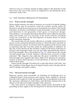
5.2 WALL AND COLUMN BEHAVIOUR UNDER AXIAL LOAD
If it were possible to apply pure axial loading to walls or columns then
the type of failure which would occur would be dependent on the
slenderness ratio, i.e. the ratio of the effective height to the effective
thickness. For short stocky columns, where the slenderness ratio is low,
failure would result from compression of the material, whereas for long
thin columns and higher values of slenderness ratio, failure would occur
from lateral instability.
A typical failure stress curve is shown in Fig. 5.1.
The actual shape of the failure stress curve is also dependent on the
properties of the material, and for brickwork, in BS 5628, it takes the form
of the uppermost curve shown in Fig. 4.4 but taking the vertical axis to
©2004 Taylor & Francis
on the slenderness ratio and the eccentricity, and the equation for
calculating the tabular values is given in Appendix B1 of the code as:
(5.1)
where e
m
is the larger value of e
x
, the eccentricity at the top of the wall,
and e
t
, the eccentricity in the mid-height region of the wall. Values of e
t
are given by the equation:
(5.2)
where (h
ef
/t) is the slenderness ratio (section 5.4) and e
a
represents an
additional eccentricity to allow for the effects of slenderness.
A graph showing the variation of ß with slenderness ratio and
eccentricity was shown previously in Fig. 4.4 and further details of the
method used for calculating ß are given in sections 5.6.2 and 5.9.
5.3.2 ENV 1996–1–1
A similar approach is used in the Eurocode, ENV 1996–1–1, except that a
capacity reduction factor Φ is used instead of ß. The effects of slenderness
and eccentricity of loading are allowed for in both Φ and ß but in a
slightly different way. In the Eurocode, values of Φ
i
at the top (or bottom)
of the wall are defined by an equation similar to that given in BS 5628
Fig. 5.2 Eccentric axial loading.
©2004 Taylor & Francis
whilst values of Φ
m
in the mid-height region are determined from a set of
curves (Fig. 4.6).
1. At the top (or bottom) of the wall values of Φ are defined by
(5.3)
where
(5.4)
where, with reference to the top (or bottom) of the wall, M
i
is the
design bending moment, N
i
the design vertical load, e
hi
the eccentricity
resulting from horizontal loads, e
a
the accidental eccentricity and t the
wall thickness. The accidental eccentricity e
a
, which allows for
construction imperfections, is assumed to be h
ef
/450 where h
ef
is the
effective height. The value 450, representing an average ‘category of
execution’, can be changed to reflect a value more appropriate to a
particular country.
2. For the middle fifth of the wall Φ
m
can be determined from Fig. 4.6
using values of h
ef
/t
ef
and e
mk
/t. Figure 4.6, used in EC6, is equivalent
to Fig. 4.4, used in BS 5628, to obtain values of Φ and ß respectively.
The value of e
mk
is obtained from:
(5.5)
where, with reference to the middle one-fifth of the wall height, M
m
is
the design bending moment, N
m
the design vertical load, e
hm
the
eccentricity resulting from horizontal loads and e
k
the creep
eccentricity defined by
e
k
=0.002Φ
∞
(h
ef
/t
m
) (te
m
)
1/2
where Φ
∞
is a final creep coefficient obtained from a table given in the
code. However, the value of e
k
can be taken as zero for all walls built
with clay and natural stone units and for walls having a slenderness
ratio up to 15 constructed from other masonry units.
Note that the notation e
a
used in EC6 is not the same quantity e
a
used in
BS 5628. They are defined and calculated differently in the two codes.
5.4 SLENDERNESS RATIO
This is the ratio of the effective height to the effective thickness, and
therefore both of these quantities must be determined for design
purposes. The maximum slenderness ratio permitted according to both
BS 5628 and ENV 1996–1–1 is 27.
©2004 Taylor & Francis
5.4.1 Effective height
The effective height is related to the degree of restraint imposed by the
floors and beams which frame into the wall or columns.
Theoretically, if the ends of a strut are free, pinned, or fully fixed then,
since the degree of restraint is known, the effective height can be
calculated (Fig. 5.3) using the Euler buckling theory.
In practice the end supports to walls and columns do not fit into these
neat categories, and engineers have to modify the above theoretical
values in the light of experience. For example, a wall with concrete floors
framing into the top and bottom, from both sides (Fig. 5.4), could be
considered as partially fixed at both ends, and for this case the effective
length is taken as 0.75h, i.e. half-way between the ‘pinned both ends’ and
the ‘fixed both ends’ cases.
In the above example it is assumed that the degree of fixity is half-way
between the pinned and fixed case, but in reality the degree of fixity is
dependent on the relative values of the stiffnesses of the floors and walls.
For the case of a column with floors framing into both ends, the
stiffnesses of the floors and columns are of a similar magnitude and the
effective height is taken as h, the clear distance between lateral supports
(Fig. 5.4).
(a) BS 5628
In BS 5628 the effective height is related to the degree of lateral resistance
to movement provided by supports, and the code distinguishes between
two types of resistance—simple and enhanced. The term enhanced
resistance is intended to imply that there is some degree of rotational
restraint at the end of the member. Such resistances would arise, for
example, if floors span to a wall or column from both sides at the same
level or where a concrete floor on one side only has a bearing greater
than 90 mm and the building is not more than three storeys.
Fig. 5.3 Effective height for different end conditions.
©2004 Taylor & Francis
where h is the clear storey height and
n
is a reduction factor where n=2,
3 or 4 depending on the edge restraint or stiffening of the wall. Suggested
values of
n
given in the code are:
• For walls restrained at the top and bottom then
2
=0.75 or 1.0 depending on the degree of restraint
• For walls restrained top and bottom and stiffened on one vertical edge
with the other vertical edge free
where L is the distance of the free edge from the centre of the
stiffening wall. If Lу15t, where t is the thickness of the stiffened wall,
take
3
=
2
.
• For walls restrained top and bottom and stiffened on two vertical
edges
where L is the distance between the centres of the stiffening walls. If
Lу30t, where t is the thickness of the stiffened wall, take
4
=
2
.
Note that walls may be considered as stiffened if cracking between the
wall and the stiffening is not expected or if the connection is designed to
resist developed tension and compression forces by the provision of
anchors or ties. These conditions are important and designers should
ensure that they are satisfied before assuming that any stiffening exists.
Stiffening walls should have a length of at least one-fifth of the storey
height and a thickness of 0.3×(wall thickness) with a minimum value of
85mm.
5.4.2 Effective thickness
The effective thickness of single leaf walls or columns is usually taken as
the actual thickness, but for cavity walls or walls with piers other
assumptions are made.
(a) BS 5628
Considering the single leaf wall with piers shown in Fig. 5.5(a) it is
necessary to decide on the value of the factor K shown in Fig. 5.5(b),
which will give a wall of equivalent thickness. Here, the meaning of
©2004 Taylor & Francis
Effective thickness is taken as the greatest value of:
•
• t
1
• Kt
2
According to the code the stiffness coefficients given in Table 5.1 can also
be used for a wall stiffened by intersecting walls if the assumption is
made that the intersecting walls are equivalent to piers of width equal to
the thickness of the intersecting walls and of thickness equal to three
times the thickness of the stiffened wall. However, recent experiments do
not confirm this. A series of tests conducted by Sinha and Hendry on
brick walls stiffened either by returns or by intersecting diaphragm walls
under axial compressive loading showed no increase in strength
compared to strip walls for a range of slenderness ratios up to 32.
(b) ENV 1996–1–1
In the Eurocode the effective thickness of a cavity wall in which the
leaves are connected by suitable wall ties is determined using:
(5.7)
5.5 CALCULATION OF ECCENTRICITY
In order to determine the value of the eccentricity, different simplifying
assumptions can be made, and these lead to different methods of
calculation. The simplest is the approximate method given in BS 5628,
but a more accurate value can be obtained, at the expense of additional
calculation, by using a frame analysis. Calculation of the eccentricity
Fig. 5.6 Cavity wall with piers.
©2004 Taylor & Francis
according to the Eurocode is performed using the equations given in
section 5.3. The approach using these equations is similar to the method
given in BS 5628.
5.5.1 Approximate method of BS 5628
1. The load transmitted by a single floor is assumed to act at one-third of
the depth of the bearing areas from the face of the wall (Figs. 5.7(a)
and (b)).
2. For a continuous floor, the load from each side is assumed to act at
one-sixth of the thickness of the appropriate face (Fig. 5.8 (a)).
3. Where joist hangers are used the load is assumed to act at the centre of
the joist bearing areas of the hanger (Fig. 5.8(b)).
4. If the applied vertical load acts between the centroid of the two leaves
of a cavity wall it should be replaced by statically equivalent axial
loads in the two leaves (Fig. 5.9).
In the above the total vertical load on a wall, above the lateral support
being considered, is assumed to be axial.
Fig. 5.7 (a) Eccentricity for floor/solid wall; (b) eccentricity for floor/cavity wall.
©2004 Taylor & Francis
Note that the eccentricity calculated above is the value at the top of the
wall or column where the floor frames into the wall. In BS 5628 the
eccentricity is assumed to vary from the calculated value at the top of the
wall to zero at the bottom of the wall, subject to an additional eccentricity
being considered to cover slenderness effects (see Chapter 4).
5.5.2 Simplified method for calculating the eccentricity
(ENV 1996–1–1)
In order to calculate the eccentricities e
i
or e
m
it is necessary to determine
the value of M
i
or M
m
and a simplified method of calculating these
moments is described in Annex C of EC6. Using the simplified frame
diagram illustrated in Fig. 5.10 in which the remote ends of each member
framing into a joint are assumed to be fixed (unless known to be free), the
bending moment M
1
can be calculated using:
(5.8)
where n is taken as 4 if the remote end is fixed and 3 if free. The value of
M
2
can be obtained from the same equation but replacing the numerator
with nE
2
I
2
/h
2
. Here E and I represent the appropriate modulus of
elasticity and second moment of area respectively, and w
3
and w
4
are the
design uniformly distributed loads modified by the partial safety factors.
If less than four members frame into a joint then the equation is modified
by ignoring the terms related to the missing members.
Fig. 5.10 Simplified frame diagram.
©2004 Taylor & Francis
The code states that this simplified method is not suitable for timber floor
joists and proposes that for this case the eccentricity be taken as у0.4t. Also,
since the results obtained from the equation tend to be conservative the code
allows the use of a reduction factor (1-k/4) if the design vertical stress is
greater than 0.25 N/mm
2
. The value of k is given by
(5.9)
where each k is the stiffness factor defined by EI/h.
5.5.3 Frame analysis
If the wall bending moment and axial load are calculated for any joint in
a multi-storey framed structure then the eccentricity can be determined
by dividing the moment by the axial load. The required moment and
axial load can be determined using a normal rigid frame analysis. This
approach is reasonable when the wall compression is high enough to
contribute to the rigidity of the joints, but would lead to inaccuracies
when the compression is small.
The complete frame analysis can be avoided by a partial analysis
which assumes that the far ends of members (floors and walls) attached
to the joint under consideration are pinned (Fig. 5.11).
The wall bending moments for the most unfavourable loading
conditions can now be determined using moment-distribution or slope-
deflection methods.
More sophisticated methods which allow for the relative rotation of
the wall and slab at the joints and changing wall stiffness due to tension
cracking in flexure are being developed.
Fig. 5.11 Multi-storey frame and typical joint.
©2004 Taylor & Francis
5.6 VERTICAL LOAD RESISTANCE
The resistance of walls or columns to vertical loading is obviously related
to the characteristic strength of the material used for construction, and it
has been shown above that the value of the characteristic strength used
must be reduced to allow for the slenderness ratio and the eccentricity of
loading. If we require the design vertical load resistance, then the
characteristic strength, which is related to the strength at failure, must be
further reduced by dividing by a safety factor for the material.
As shown in Chapter 4 the British code introduces a capacity
reduction factor ß which allows simultaneously for effects of eccentricity
and slenderness ratio. It should be noted that these values of ß are for
use with the assumed notional values of eccentricity given in the code,
and that if the eccentricity is determined by a frame type analysis which
takes account of continuity then different capacity reduction factors
should be used.
As shown in section 5.3 the Eurocode introduces the capacity
reduction factor Φ which is similar to, but not identical with, the factor ß
used in BS 5628.
If tensile strains are developed over part of a wall or column then
there is a reduction in the effective area of the cross-section since it can be
assumed that the area under tension has cracked. This effect is of
importance for high values of eccentricity and slenderness ratio, and the
Swedish code allows for it by introducing the ultimate strain value for
the determination of the reduction factor.
5.6.1 Design vertical load resistance of walls
Using the principles outlined above the design vertical load resistance
per unit length of wall is given in BS 5628 as (ßtf
k
)/
␥
m
where
␥
m
is the
partial safety factor for the material and ß is obtained from Fig. 4.4. In the
Eurocode the design vertical load resistance per unit length of wall is
given as (Φtf
k
)/
␥
m
where Φ is determined either at the top (or bottom),
Φ
i
, or in the middle fifth of the wall, Φ
m
.
The procedure for calculating the design vertical load resistance in BS
5628 can be summarized as follows:
1. Determine e
x
at the top of the wall using the method illustrated in Figs
5.7 to 5.9.
2. Determine e
a
, the additional eccentricity, using equation (4.2) and the
total eccentricity e
t
using equation (4.3).
3. If e
x
>e
t
then e
x
governs the design. If e
t
>e
x
then e
t
(the eccentricity at
mid-height) governs.
4. Taking e
m
to represent the larger value of e
x
and e
t,
then if e
m
is р0.05t
the design load resistance is given by (ßtf
k
)/
␥
m
, with ß=1, and if e
m
©2004 Taylor & Francis
>0.05t the design load resistance is given by (ßtf
k
)/
␥
m
, with ß=1.1(1-
2e
m
/t).
5.6.2 Design vertical load resistance of columns
For columns the design vertical load resistance is given in BS 5628 as
(ßtf
k
)/
␥
m
, but for this case the rules in Table 5.2 apply to the selection of ß
from Fig. 4.4.
If the eccentricities at the top of the column about the major and minor
axes are greater than 0.05b and 0.05t respectively, then the code
recommends that the values of ß can be determined from the equations
given in Appendix B of BS 5628. The method can be summarized as
follows (Fig. 5.12):
1. About XX axis
• The design eccentricity e
m
about XX is defined as the larger value of
e
x
and e
t
, where
and (h
ef
/t) is the slenderness ratio about the minor axis.
• The value of ß is calculated from
Table 5.2 Rules for selecting ß for columns
©2004 Taylor & Francis
About XX axis
e
m
=e
x
=20 mm
or
So
About YY axis
or
For this case the bracketed term is negative, because the slenderness ratio
is less than 6, and therefore no additional term due to slenderness effect
is required. That is e
m
=60 mm and
Note that the design vertical load resistance for the above example
would be
(a)
(b)
Fig. 5.13 Dimensions of worked example.
©2004 Taylor & Francis
That is, the largest value of ß
XX
and ß
YY
is used in order to ensure that the
smaller value of f
k
will be determined when the design vertical load
resistance is equated to the design vertical load.
No specific references to the design of columns are given in the
Eurocode although a similar approach to that outlined above but
replacing ß with Φ would be possible.
5.6.3 Design vertical load resistance of cavity walls or columns
The design vertical load resistance for cavity walls or columns can be
determined using the methods outlined in sections 5.6.1 and 5.6.2 if the
vertical loading is first replaced by the statically equivalent axial load on
each leaf. The effective thickness of the cavity wall or column is used for
determining the slenderness ratio for each leaf of the cavity.
5.6.4 Design vertical strength for concentrated loads
Increased stresses occur beneath concentrated loads from beams and
lintels, etc. (see Fig. 4.5), and the combined effect of these local stresses
with the stresses due to other loads should be checked. The concentrated
load is assumed to be uniformly distributed over the bearing area.
(a) BS 5268
In BS 5628 two design checks are suggested:
• At the bearing, assuming a local design bearing strength of either
1.25f
k
/
␥
m
or 1.5f
k
/
␥
m
depending on the type of bearing.
• At a distance of 0.4h below the bearing, where the design strength is
assumed to be ßf
k
/
␥
m
. The concentrated load is assumed to be
dispersed within a zone contained by lines extending downwards at
45° from the edges of the loaded area (Fig. 5.14).
The code also makes reference to the special case of a spreader beam
located at the end of a wall and spanning in its plane. For this case the
maximum stress at the bearing, combined with stresses due to other
loads, should not exceed 2.0 f
k
/
␥
m
.
(b) ENV 1996–1–1
In ENV 1996–1–1 the following checks are suggested:
• For Group 1 masonry units, the local design bearing strength must not
exceed the value derived from
(5.10)
©2004 Taylor & Francis
eccentricities. The design process for vertical loading is completed by
equating the design vertical loading to the appropriate design vertical
load resistance and using the resulting equation to determine the value
of the characteristic compressive strength of the masonry f
k
. Typically the
equation takes the form
(5.11)
Generally the calculation of ΣW involves the summation of products of
the partial safety factor for load (
␥
f
) with the appropriate characteristic
load (G
k
and Q
k
). This is discussed in Chapter 4 and illustrated in
Chapter 10. For design according to the Eurocode, ß in equation (5.11)
would be replaced by Φ.
Using standard tables or charts and modification factors where
applicable, the compressive strength of the masonry units and the required
mortar strength to provide the necessary value of f
k
can be obtained.
Examples of the calculation for an inner solid brick wall and an
external cavity wall are given in section 5.9.
5.8 MODIFICATION FACTORS
The value of f
k
used in Fig. 4.1, in order to determine a suitable masonry/
mortar combination, is sometimes modified to allow for the effects of
small plan area or narrow masonry walls.
5.8.1 Small plan area
(a) BS 5628
If the horizontal cross-sectional area (A) is less than 0.2 m
2
then the value
of f
k
determined from an equation similar to (5.11) is divided by a factor
(0.70+1.5A).
(b) ENV 1996–1–1
If the horizontal cross-sectional area (A) is less than 0.1 m
2
then the value
of f
k
determined from an equation similar to (5.11) is divided by a factor
(0.70+3A).
5.8.2 Narrow masonry walls
In BS 5628 a modification factor is also given for narrow walls. If the
thickness of the wall is equal to the width of the masonry then the value
of f
k
determined from an equation similar to (5.11) is divided by 1.15.
©2004 Taylor & Francis