DESIGN OF MASONRY STRUCTURES Part 9 doc
Bạn đang xem bản rút gọn của tài liệu. Xem và tải ngay bản đầy đủ của tài liệu tại đây (701.84 KB, 24 trang )
Table 12.1 Loading on wall A per metre run
©2004 Taylor & Francis
Table 12.1 (Contd)
©2004 Taylor & Francis
©2004 Taylor & Francis
Table 12.2 Loading on wall B per metre run; inner leaf
©2004 Taylor & Francis
©2004 Taylor & Francis
walls will provide the resistance to wind loading. In an actual design, the
designer must of course check that the structure is safe for wind blowing
east-west and vice versa.
In the calculation below it has further been assumed that the walls act
as independent cantilevers; and hence moments or forces are
apportioned according to their stiffness.
12.5.2 Wind loads
These are calculated according to CP 3, Chapter V: Part 2. We have
Using ground roughness category 3, Class B, with height of the
building=21.0m, from Table 3, CP3, Chapter V: Part 2
Therefore design wind speed is
and dynamic wind pressure is
From Clause 7.3, CP3, Chapter V: Part 2, total wind force
The total maximum bending moment is
total max. BM=F×h/2
where h is the height under consideration. Total BM just above floor level
is given for each floor by:
• 6th floor
C
f
qA
e
×h/2=1.1×(1269/10
3
)×21×3×3/2=131.9kNm
• 5th floor
1.1×(1269/10
3
)×21×6×3=527.6kNm
• 4th floor
(1.1×1269×21/10
3
)×9×9/2=1187.20kNm
• 3rd floor
29.313×(12×12/2)=2110.54kNm
• 2nd floor
29.313×(15×15/2)=3297.70kNm
©2004 Taylor & Francis
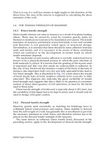
Fig. 12.3 The variation of the factor S
2
and the wind velocity along the height of
the building. (Assumptions made in the design shown in full lines.)
©2004 Taylor & Francis
• 1st floor
29.313×(18×18/2)=4748.71kNm
• ground floor
1.1×(1269/10
3
)×21×21×21/2=6463.2kNm
In the calculation the factor S
2
has been kept constant (Fig. 12.3), which
means the design will be a bit conservative. However, the reader can
vary the S
2
factor as given in Fig. 12.3 taken from Table 3 (CP 3) which
means the wind speed will be variable depending on the height of the
building.
12.5.3 Assumed section of wall resisting the wind moment
The flange which acts together with the web of I-section is the lesser of
• 12 times thickness of flange+thickness of web
• centre line to centre line of walls
• one-third of span
(a) Wall A
For wall A (Fig. 12.4), neglecting the outer skin of the cavity wall flange,
the second moment of area is
(b) Wall B
The flange width which acts with channel section has been assumed as
half of the I-section. For wall B (Fig. 12.5), neglecting the outer skin of the
cavity wall flange,
©2004 Taylor & Francis
Table 12.3 Distribution of bending moment stresses and shear force in walls
©2004 Taylor & Francis
©2004 Taylor & Francis
©2004 Taylor & Francis
©2004 Taylor & Francis
©2004 Taylor & Francis
©2004 Taylor & Francis
12.6.2 Selection of brick and mortar combinations for wall
A:BS 5628
Design vertical load resistance of wall is (ßtf
k
)/g
m
(clause 32.2.1),
eccentricity Hence ß=0.67
©2004 Taylor & Francis
(Table 7 of BS 5628),
␥
m
=3.5 (see section 12.3). The design loads from the
previous subsection and the characteristic strengths are shown in Table
12.4 along with the suitable brick/mortar combinations.
Check for shear stress: design characteristic shear f
v
=
␥
f
␥
mv
(shear force/
area) < 0.35 +0.6g
A
(clause 25),
␥
f
=1.4 and
␥
mv
=2.5 (12.3). The value of
shear force is taken from Table 12.3. For the sixth floor
For the ground floor
There is no need to check at any other level, since shear is not a problem
for this type of structure.
The BS 5628 recommends g
A
as the design vertical load per unit area of
wall cross-section due to vertical load calculated from the appropriate
loading condition specified in clause 22. The critical condition of shear
will be with no imposed load just after and during the construction.
12.6.3 Load combination, wall B
The design principle has been covered in great detail for wall A; hence
for wall B this will be limited to the ground floor level to explain further
salient points.
Inner leaf wall B –ground floor level
(i) Dead and imposed loads
©2004 Taylor & Francis
Table 12.4 Design load and characteristic brickwork strength
©2004 Taylor & Francis
The worst combination for this wall just above ground level also is
dead+wind, and the design load is (1.96×102.5×10
3
)/10
3
=201kN/m.
12.6.4 Selection of brick and mortar for inner leaf of wall B
The design vertical load resistance of the wall is (ßtf
k
)/
␥
m
(clause 32.2.1).
The value of ß depends on the eccentricity of loading; hence the value of
e needs to be evaluated before design can be completed.
12.6.5 Calculation of eccentricity
The worst combination of loading for obtaining the value of e at top of
the wall is shown in Fig. 12.6. Axial load
P=(0.9×78.54+1.6×7.29) (G
k
and Q
k
from Table 12.2)
=(70.69+11.66)=82.35kN/m
First floor load
P
1
=(1.4×6.48+1.6×2.025) (see Table 12.2)
=12.31kN/m
©2004 Taylor & Francis
BM at centre of the panel=627.8×(Cp
e
+CP
i
)h
2
×0.104×1.4
=627.8×(1.1+0.2)×(2.85)
2
×0.104×1.4
=964.6Nm/m (Cp
e
and Cp
i
from CP3, Chapter V: Part 2)
(BM coefficient for four-sided simply supported panel is 0.104; table 3.1,
BS 8110)
(since both leaves are of same stiffness)
where
Resultant
(b) Wind blowing west-east direction
The panel B is not only subjected to dead and imposed loads, but also
subjected to wind loading from west to east direction. Then
(the bending moment induced due to wind loading acts against those
due to the vertical load).
Since resultant eccentricity of case (b) is greater than case (a), case (b)
eccentricity is considered in the design.
©2004 Taylor & Francis
12.6.6 Calculation of characteristic compressive stress f
k
for wall B
(inner leaf)
12.6.7 Design of the outer leaf of the cavity wall B in GF
Load combination:
• Windward side
©2004 Taylor & Francis
• Leeward side
The design is similar to the inner leaf and will not be considered any
further. The slight tension which is developing is of no consequence,
since 6 to 10% of the dead and imposed load will be transferred to the
outer leaf even in cases where the slab is supported on the inner skin.
The bending stress caused by the wind will be smaller if S
2
factor is
assumed variable as explained in section 12.5.2: the staircase and lift well
will also provide the stability against the wind which has been neglected.
However, any facing brick having water absorption between 7 and 12%
in 1:¼:3 mortar may be used, provided that it satisfies the lateral load
design. The grade of mortar is kept the same as for the inner leaf.
Characteristic flexural strength:
(Table 3)
Design characteristic shear as in inner leaf:
Instead of the conventional design calculations described in this chapter
a more sophisticated analysis of the structure is possible by idealizing it
as a frame with vertical loading as shown in Fig. 12.7. Similarly, the
structure can be idealized and replaced by a two-dimensional frame (Fig.
12.8) and analysed as discussed in Chapter 6 for wind loading.
12.7 DESIGN CALCULATION ACCORDING TO EC6 PART 1–1
(ENV 1996–1:1995)
To demonstrate the principle of design according to EC6, the wall A in
the ground floor will be redesigned. The dead and live loading is taken
as calculated before and as in Table 12.1. The bending moments and
shear forces due to wind loading are given in Table 12.3. The category of
manufacturing and execution controls are assumed to be II and C
respectively; thus
␥
m
=3 as given in Table 4.6.
Load combination for ultimate limit state:
©2004 Taylor & Francis
• Windward side
• Leeward side
Hence, most unfavourable action is 1.35G
kj
+1.35Q
ki
+1.35 W
ki
and the
design load=3.17×102.5×10
3
/10
3
=324.9kN/m.
12.7.1 Selection of brick and mortar combination for wall A:
according to EC6
Design vertical load resistance of wall , where depends
on eccentricity and slenderness ratio .
12.7.2 Calculation of eccentricity
Figure 12.9 shows the worst combination of loading for obtaining the
value of eccentricity. Axial load
©2004 Taylor & Francis
Fig. 12.9 Calculation of eccentricity of the loading (not to scale).
©2004 Taylor & Francis
EC6 allows the use of the value from the national code. Hence 50N/mm
2
brick in mortar will be sufficient.
In the absence of test data a formula as given below is suggested for
use:
or
Therefore, 100N/mm
2
bricks are required which is much higher than the
previous case. It would be better and economical to do tests on prisms to
obtain the characteristic strength.
For the ground floor
␥
G
has been taken as 1 for favourable effect.
The allowable shear due to precompression in BS 5628 is higher than
in the Eurocode, but it does not make much difference to the design.
12.8 DESIGN OF PANEL FOR LATERAL LOADING: BS 5628
(LIMIT STATE)
To explain the principle of the design only panel B between sixth floor
and roof will be considered. The low precompression on the inner leaf is
ignored in this design. Assume:
• Inner leaf 102.5mm brickwork in 1:1:6 mortar
• Outer leaf 102.5mm brickwork with facing brick in 1:1:6 mortar
• Boundary conditions: two sides simply supported and two sides fixed
as shown in Fig. 12.10.
©2004 Taylor & Francis