DESIGN OF MASONRY STRUCTURES Part 10 pps
Bạn đang xem bản rút gọn của tài liệu. Xem và tải ngay bản đầy đủ của tài liệu tại đây (431.21 KB, 23 trang )
12.8.1 Limiting dimension: clause 36.3, BS 5628: case B
The dimensions h×1 of panels supported on four edges should be equal
to or less than 2025 (t
ef
)
2
:
12.8.2 Characteristic wind load W
k
The corner panel is subjected to local wind suctions. From CP 3, Chapter
V, total coefficient of wind pressure,
The design wind velocity
where S
1
=S
3
=1.
Using ground roughness Category (3), Class A, and height of the
building=21m, therefore
Fig. 12.10 Panel, simply supported top and bottom and fixed at its vertical
edges.
©2004 Taylor & Francis
Note that
␥
f
is taken as 1.4 since inner leaf is an important loadbearing
element. The designer may, however, use
␥
f
=1.2 in other circumstances.
Use bricks having water absorption less than 7% in 1:1:6 mortar.
12.9 DESIGN FOR ACCIDENTAL DAMAGE
12.9.1 Introduction
The building which has been designed earlier in this chapter falls in
Category 2 (table 12, BS 5628) and hence the additional recommendation
of clause 37 to limit the extent of accidental damage must be met over
and above the recommendations in clause 20.2 for the preservation of
structural integrity.
©2004 Taylor & Francis
Three options are given in the code in Table 12. Before these options
are discussed it would be proper to consider whether the walls A and B
in the ground floor, carrying heaviest precompression, can be designated
as protected elements.
12.9.2 Protected wall
A protected wall must be capable of resisting 34 kN/m
2
from any
direction. Let us examine wall A first.
(a) Wall A
Load combination=0.95G
k
+0.35Q
k
+ 0.35W
k
(clause 22)
G
k
=the load just below the first floor. So
Therefore
(b) Lateral strength of wall with two returns
hence k=2.265. (Note that in clause 37.1.1 a factor of 7.6, which is equal to
8/1.05, has now been suggested.)
Hence this wall cannot strictly be classified as a protected member.
Since wall A, carrying a higher precompression, just fails to resist 34
kN/m
2
pressure, wall B, with a lower precompression, obviously would
not meet the requirement for a protected member.
Further, for both walls
©2004 Taylor & Francis
Neither wall A nor B can resist 34kN/m
2
. Even if they did, they do not
fulfil the requirement of clause 36.8 that
It may be commented that the basis of this provision in the code is
obscure and conflicts with the results of tests on laterally loaded walls.
Other options therefore need to be considered in designing against
accidental damage.
12.9.3 Accidental damage: options
(a) Option 1
Option 1 requires the designer to establish that all vertical and horizontal
elements are removable one at a time without leading to collapse of any
significant portion of the structure. So far as the horizontal members are
concerned, this option is superfluous if concrete floor or roof slabs are
used, since their structural design must conform to the clause 2.2.2.2(b)
of BS 8110:1985.
(b) Option 3
For the horizontal ties option 3 requirements are very similar to BS
8110:1985. In addition to this, full vertical ties need to be provided. This
option further requires that the minimum thickness of wall should be 150
mm, which makes it a costly exercise. No doubt it would be difficult to
provide reinforcements in 102.5mm wall. However, there could be several
ways whereby this problem could be overcome. This option is impracticable
in brickwork although possibly feasible for hollow block walls.
(c) Option 2
The only option left is option 2, which can be used in this case. The
horizontal ties are required by BS 8110:1985 to be provided in any case. In
addition the designer has to prove that the vertical elements one at a time
can be removed without causing collapse.
12.9.4 Design calculations for option 2: BS 5628
(a) Horizontal ties
Basic horizontal tie force, F
t
=60kN or 20+4N
s
whichever is less.
N
s
=number of storeys. Then
Hence use 48kN.
©2004 Taylor & Francis
(b) Design tie force (table 13, BS 5628)
• Peripheral ties: Tie force, F
t
=48kN.
As required: (48×10
3
)/250=192 mm
2
Provide one 16mm diameter bar as peripheral tie (201mm
2
) at roof and
each floor level uninterrupted, located in slab within 1.2m of the edge
of the building.
• Internal ties: Design tie force F
t
or whichever
is greater in the direction of span. Tie force
(For the roof the factor G
k
is 3.5.) Therefore F
t
=48kN/m. (Also note
L
a
<5×clear height=5×2.85=14.25m.) Span of corridor slab is less than
3m, hence is not considered. Tie force normal to span, F
t
=48kN/m.
Provide 10mm diameter bar at 400mm centre to centre in both
directions. Area provided 196mm
2
(satisfactory).
Internal ties should also be provided at each floor level in two directions
approximately at right angles. These ties should be uninterrupted and
anchored to the peripheral tie at both ends. It will be noted that
reinforcement provided for other purposes, such as main and
distribution steel, may be regarded as forming a part of, or whole of,
peripheral and internal ties (see section 12.10).
(c) Ties to external walls
Consider only loadbearing walls designated as B.
Therefore
design tie force=54kN/m
(d) Tie connection to masonry (Fig. 12.11)
Ignoring the vertical load at the level under consideration, the design
characteristic shear stress at the interface of masonry and concrete is
©2004 Taylor & Francis
deflect due to the removal of this support but also have to carry the wall
load above it without collapsing. As long as every floor takes care of the
load imposed on it without collapsing, there is no likelihood of the
progressive collapse of the building. This is safer than assuming that the
wall above may arch over and transfer the load to the outer cavity and
inner corridor walls. Fig. 12.12 shows one of the interior first floor slabs,
and the collapse—moment will be calculated by the yield line method.
The interior slab has been considered, because this may be more critical
than the first interior span, in which reinforcement provided will be
higher compared with the interior span. The design calculation for the
interior span is given in section 12.10.
The yield-line method gives an upper-bound solution; hence other
possible modes were also tried and had to be discarded. It seems that the
slab may collapse due to development of yield lines as shown in Fig.
12.12. On removal of wall A below, it is assumed that the slab will behave
as simply supported between corridor and outer cavity wall (Fig. 12.1)
because of secondary or tie reinforcement.
(a) Floor loading
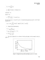
Fig. 12.12 The yield-line patterns at the collapse of the first floor slab under
consideration.
©2004 Taylor & Francis
Note that
␥
f
can be reduced to 0.35. According to the code in combination
with DL,
␥
f
factor for LL can be taken as 0.35 in the case of accidental
damage. However, it might just be possible that the live load will be
acting momentarily after the incident.
(b) Calculation for failure moment
The chosen x and y axes are shown in Fig. 12.12. The yield line ef is given
a virtual displacement of unity. External work done=Σw
δ
, where w is the
load and
δ
is the deflection of the CG of the load. So
(12.58)
©2004 Taylor & Francis
From equations (12.57) and (12.58)
or
(12.59)
For maximum value of moment dm/dß=0, from which
The positive root of this equation is
Substituting the value of ß in equation (12.59), we get
Then required A
s
is
Owing to removal of support at the ground floor, there will be minimal
increase in stresses in the outer cavity and corridor wall. The wall type A
(AD and BC in Fig. 12.10) may be relieved of some of the design load,
hence no further check is required.
12.10 APPENDIX: A TYPICAL DESIGN CALCULATION
FOR INTERIOR-SPAN SOLID SLAB
This is shown in the form of a table (Table 12.5).
©2004 Taylor & Francis
Table 12.5 (Contd)
©2004 Taylor & Francis
13
Movements in masonry buildings
13.1 GENERAL
Structural design is primarily concerned with resistance to applied loads
but attention has to be given to deformations which result from a variety
of effects including temperature change and, in the case of masonry,
variations in moisture content. Particular problems can arise when
masonry elements are constrained by interconnection with those having
different movements, which may result in quite severe stresses being set
up. Restraint of movement of a brittle material such as masonry can lead
to its fracture and the appearance of a crack. Such cracks may not be of
structural significance but are unsightly and may allow water
penetration and consequent damage to the fabric of the building.
Remedial measures will often be expensive and troublesome so that it is
essential for movement to receive attention at the design stage.
13.2 CAUSES OF MOVEMENT IN BUILDINGS
Movement in masonry may arise from the following causes:
• Moisture changes
• Temperature changes
• Strains due to applied loads
• Foundation movements
• Chemical reactions in materials
13.2.1 Moisture movements
Dimensional changes take place in masonry materials with change in
moisture content. These may be irreversible following manufacture—
thus clay bricks show an expansion after manufacture whilst concrete
and calcium silicate products are characterized by shrinkage. All types of
masonry exhibit reversible expansion or shrinkage with change in
©2004 Taylor & Francis
moisture content at all stages of their existence. Typical values are shown
in Table 13.1.
13.2.2 Thermal movements
Thermal movements depend on the coefficient of expansion of the
material and the range of temperature experienced by the building
element. Values of the coefficient of expansion are indicated in Table 13.1
but estimation of the temperature range is complicated depending as it
does on other thermal properties such as absorptivity and capacity and
incident solar radiation. The temperature range experienced in a heavy
exterior wall in the UK has been given as -20 °C to +65
º
C but there are
likely to be wide variations according to colour, orientation and other
factors.
13.2.3 Strains resulting from applied loads
Elastic and creep movements resulting from load application may be a
factor in high-rise buildings if there is a possibility of (differential
movement between a concrete or steel frame and masonry cladding or
infill. Relevant values of elastic modulus and creep coefficients are
quoted in Chapter 4.
13.2.4 Foundation movements
Foundation movements are a common cause of cracking in masonry
walls and are most often experienced in buildings constructed on clay
soils which are affected by volume changes consequent on fluctuation in
soil moisture content. Soil settlement on infilled sites and as a result of
mining operations is also a cause of damage to masonry walls in certain
areas. Where such problems are foreseen at the design stage suitable
Table 13.1 Moisture and thermal movement indices for masonry materials,
concrete and steel
©2004 Taylor & Francis
precautions can be taken in relation to the design of the foundations, the
most elementary of which is to ensure that the foundation level is at least
1m below the ground surface. More elaborate measures are of course
required to cope with weak soils or mining subsidence.
13.2.5 Chemical reactions in materials
Masonry materials are generally very stable and chemical attack in service
is exceptional. However, trouble can be experienced as the result of
sulphate attack on mortar and on concrete blocks and from the corrosion
of wall ties or other steel components embedded in the masonry.
Sulphate solution attacks a constituent of cement in mortar or concrete
resulting in its expansion and disintegration of the masonry. The soluble
salts may originate in ground water or in clay bricks but attack will only
occur if the masonry is continuously wet. The necessary precaution lies
in the selection of masonry materials, or if ground water is the problem,
in the use of a sulphate-resistant cement below damp-proof course level.
13.3 HORIZONTAL MOVEMENTS IN MASONRY WALLS
Masonry in a building will rarely be free to expand or contract without
restraint but, as a first step towards appreciating the magnitude of
movements resulting from moisture and thermal effects, it is possible to
deduce from the values given in Table 13.1 the theoretical maximum
change in length of a wall under assumed thermal and moisture
variations. Thus the maximum moisture movement in clay brick
masonry could be an expansion of 1mm in 1m. The thermal expansion
under a temperature rise of 45°C could be 0.3mm so that the maximum
combined expansion would be 1.3 mm per metre. Aerated concrete
blockwork on the other hand shrinks by up to 1.2 mm per metre and
has about the same coefficient of thermal expansion as clay masonry so
that maximum movement would be associated with a fall in
temperature.
Walls are not, in practical situations, free to expand or contract
without restraint but these figures serve to indicate that the potential
movements are quite large. If movement is suppressed, very large forces
can be set up, sufficient to cause cracking or even more serious damage.
Provision for horizontal movement is made by the selection of suitable
materials, the subdivision of long lengths of wall by vertical movement
joints and by the avoidance of details which restrain movement and give
rise to cracking.
The spacing of vertical movement joints is decided on the basis of
empirical rules rather than by calculation. Such joints are filled with a
©2004 Taylor & Francis
compressible sealant and their spacing will depend on the masonry
material. An upper limit of 15 m is appropriate in clay brickwork, 9 m in
calcium silicate brickwork and 6 m in concrete blockwork. Their width in
millimetres should be about 30% more than their spacing in metres.
Location in the building will depend on features of the building such as
intersecting walls and openings. It should be noted that the type of
mortar used has an important influence on the ability of masonry to
accommodate movement: thus a stone masonry wall in weak lime
mortar can be of very great length without showing signs of cracking.
Brickwork built in strong cement mortar, on the other hand, will have a
very much lower tolerance of movement and the provision of movement
joints will be essential.
Certain details, such as short returns (Fig. 13.1) are particularly
vulnerable to damage by moisture and thermal expansion. Similar
damage can result from shrinkage in calcium silicate brickwork or
concrete blockwork. Parapet walls are exposed to potentially extreme
variations of temperature and moisture and their design for movement
therefore requires special care. A considerable amount of guidance on
these points is provided in BS 5628: Part 3.
Fig. 13.1 Cracking at a short return in brick masonry.
©2004 Taylor & Francis
13.4 VERTICAL MOVEMENTS IN MASONRY WALLS
Vertical movements in masonry are of the same order as horizontal
movements but stress-related movements in multi-storey walls will be of
greater significance. Vertical movements are of primary importance in
the design of cavity walls and masonry cladding to reinforced concrete
or steel-framed buildings. This is because the outer leaf of masonry will
generally have different characteristics to those of the inner leaf or
structure and will be subjected to different environmental conditions.
This will result in differential movements between the outer leaf and the
inner wall which could lead to loosening of wall ties or fixtures between
them or in certain circumstances to serious damage to the masonry
cladding.
To avoid problems from this cause, BS 5628: Part 1 states that the outer
leaf of an external cavity wall should be supported at intervals of not
more than three storeys or 9m (12m in a four-storey building).
Alternatively, the relative movement between the inner wall and the
outer leaf may be calculated and suitable ties and details provided to
allow such movement to take place.
The approximate calculation of vertical movements in a multi-storey,
non-loadbearing masonry wall may be illustrated by the following
example, using hypothetical values of masonry properties. Height of
wall=24m. Number of storeys=8.
• Moisture movements. Irreversible shrinkage of masonry, 0.00525%.
Shrinkage in height of wall, 0.0000525×24×10=1.26mm. Reversible
moisture movement from dry to saturated state, ±0.04%. Moisture
movement taking place depends on moisture content at time of construction.
Assuming 50% saturation at this stage reversible movement may be
0.5×0.0004×24×10
3
=+4.8mm.
Table 13.2 Elastic and creep deformations
©2004 Taylor & Francis
• Elastic and creep movements. Elastic modulus of masonry, 2100N/mm
2
. Creep
deformation, 1.5×elastic deformation. Elastic and creep deformations,
due to self-weight, at each storey level are tabulated in Table 13.2.
• Thermal movement. Coefficient of thermal expansion, 10×10
-6
per °C.
Assumed temperature at construction, 10°C. Minimum mean
temperature of wall, -20°C. Maximum mean temperature of wall,
50°C. Range in service from 10°C, -10°C to +40°C Overall contraction
of wall
30×10×10
-6
×24×10
3
=7.2mm
Overall expansion of wall
40×10×10
-6
×24×10
3
=12.8mm
The maximum movement at the top of the wall due to the sum of these
effects is as follows:
Shown in the right-hand column are comparable figures for a clay
brickwork inner wall which would show irreversible moisture expansion
rather than contraction and would reach a stable moisture state after
construction so that irreversible moisture movement has been omitted in
this case. The wall would also experience a rise in temperature when the
building was brought into service and thus thermal expansion would
take place. In this example there would be a possible differential
movement at the top of the wall of 38.7mm but as movements are
cumulative over the height of the wall it is of interest to calculate the
relative movements at storey levels.
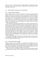
This calculation is set out in detail for the outer wall in Table 13.3. The
corresponding figures for the inner wall and the relative movements
which would have to be accommodated at each storey level are also
shown in the table and graphically in Fig. 13.2. Note that if the walls are
built at the same time the differential movement due to elastic
compression is reduced since the compression below each level will have
taken place before the ties are placed. Thus the relative wall tie
movement due to elastic compression at the top level will be zero.
©2004 Taylor & Francis
service. A concrete main structure will, however, develop shrinkage and
creep strains after completion which will have to be allowed for in
estimating differential movements relative to a masonry cladding. If
masonry cladding is built between concrete floor slabs, as in Fig. 13.3(a),
a serious problem can be created if the masonry expands and the
concrete frame shrinks unless this relative movement is allowed for by
suitable detailing as in Fig. 13.3(b).
Fig. 13.3 (a) Bowing of infill wall and detachment of brick slips as a result of
frame shrinkage, (b) Detail of horizontal movement joint to avoid damage of the
kind shown in (a).
©2004 Taylor & Francis
Notation
BS 5628
A cross-sectional area of masonry (mm
2
)
A
ps
cross-sectional area of prestressing steel (mm
2
)
A
s
cross-sectional area of primary reinforcing steel (mm
2
)
A
sv
cross-sectional area of reinforcing steel resisting shear forces
(mm
2
)
A
s1
area of compression reinforcement in the most compressed
face (mm
2
)
A
s2
area of reinforcement in the least compressed face (mm
2
)
a shear span (mm
2
)
a
v
distance from face of support to the nearest edge of a princip
al load (mm)
b width of section (mm)
b
c
width of compression face midway between restraints (mm)
b
1
width of section at level of the tension reinforcement (mm)
c lever arm factor
d effective depth (mm)
d
c
depth of masonry in compression (mm)
d
1
depth from the surface to the reinforcement in the more
highly compressed face (mm)
d
2
depth of the centroid of the reinforcement from the least
comp ressed face (mm)
E
c
modulus of elasticity of concrete (kN/mm
2
)
E
m
modulus of elasticity of masonry (kN/mm
2
)
E
m
, E
b
modulus of elasticity of mortar and brick (kN/mm
2
)
E
s
modulus of elasticity of steel (kN/mm
2
)
E
x
, E
y
modulus of elasticity in x and y direction (kN/mm
2
)
e eccentricity
e
a
additional eccentricity due to deflection in walls
e
m
the larger of e
x
or e
t
e
t
total design eccentricity in the mid-height region of a wall
e
x
eccentricity at top of a wall
©2004 Taylor & Francis
F
k
characteristic load
F
t
tie force
f
b
characteristic anchorage bond strength between mortar or
concrete infill and steel (N/mm
2
)
f
ci
strength of concrete at transfer (N/mm
2
)
f
k
characteristic compressive strength of masonry (N/mm
2
)
f
kx
characteristic flexural strength (tension) of masonry (N/mm
2
)
f
m
masonry strength
f
pb
stress in tendon at the design moment of resistance of the
section (N/mm
2
)
f
pe
effective prestress in tendon after all losses have occurred
(N/mm
2
)
f
pu
characteristic tensile strength of prestressing tendons
(N/mm
2
)
f
s
stress in the reinforcement (N/mm
2
)
f
su
stress in steel at failure
f
s1
stress in the reinforcement in the most compressed face
(N/mm
2
)
f
s2
stress in the reinforcement in the least compressed face
(N/mm
2
)
f
v
characteristic shear strength of masonry (N/mm
2
)
f
y
characteristic tensile strength of reinforcing steel (N/mm
2
)
G
k
characteristic dead load
g
A
design vertical load per unit area
g
d
design vertical dead load per unit area
h clear height of wall or column between lateral supports
h
a
clear height of wall between concrete surfaces or other
construction capable of providing adequate resistance to
rotation across the full thickness of a wall
h
ef
effective height or length of wall or column
h
L
clear height of wall to point of application of a lateral load
K stiffness coefficient
k multiplication factor for lateral strength of axially loaded
walls
L length
L
a
span in accidental damage calculation
M bending moment due to design load (N mm)
M
a
increase in moment due to slenderness (N mm)
M
d
design moment of resistance (N mm)
M
x
design moment about the x axis (N mm)
M
x
effective uniaxial design moment about the x axis (N mm)
M
y
design moment about the y axis (N mm)
M
y
effective uniaxial design moment about the y axis (N mm)
N design axial load (N)
©2004 Taylor & Francis
N
d
design axial load resistance (N)
N
dz
design axial load resistance of column, ignoring all bending
(N)
P, P
e
prestressing forces
p overall section dimension in a direction perpendicular to the
x axis (mm)
Q moment of resistance factor (N/mm
2
)
Q
k
characteristic imposed load (N)
q overall section dimension in a direction perpendicular to the
y axis (mm)
q
lat
design lateral strength per unit area
q
0
, q
1
, q
2
transverse or lateral pressure
t overall thickness of a wall or column (mm)
t
ef
effective thickness of a wall or column (mm)
t
f
thickness of a flange in a pocket-type wall (mm)
V shear force due to design loads (N)
v, v
h
shear stress due to design loads (N/mm
2
)
W
k
characteristic wind load (N)
Z, Z
1
, Z
2
section modulus (mm
3
)
z lever arm (mm)
␣
bending moment coefficient for laterally loaded panels in BS
5628
ß capacity reduction factor for walls allowing for effects of
slenderness and eccentricity
␥
f
partial safety factor for load
␥
m
partial safety factor for material
␥
mb
partial safety factor for bond strength between mortar or
concrete infill and steel
␥
mm
partial safety factor for compressive strength of masonry
␥
ms
partial safety factor for strength of steel
␥
mv
partial safety factor for shear strength of masonry
ε
strain as defined in text
λ
1
,
λ
2
stress block factors
µ
f
coefficients of friction
b
,
m
Poisson’s ratio for brick and mortar
x
,
y
Poisson’s ratios in x and y direction
µ orthogonal ratio
A
s
/bd
σ
compressive stress
σ
b
compressive stress in brick
σ
m
compressive stress in mortar or in masonry
σ
s
stress in steel
φ
creep loss factor
©2004 Taylor & Francis
EC6 (WHERE DIFFERENT FROM BS 5628)
e
a
eccentricity resulting from construction inaccuracies
e
hi
eccentricity resulting from lateral loads
e
i
eccentricity at top or bottom of wall
e
k
eccentricity allowance for creep
e
mk
eccentricity at mid-height of wall
f
b
normalized unit compressive strength
f
m
specified compressive strength of mortar
f
tk
characteristic tensile strength of steel
f
vk
characteristic shear strength of masonry
f
yk0
shear strength of masonry under zero compressive stress
f
yk
characteristic yield strength of steel
I second moment of area
K constant concerned with characteristic strength of masonry
k stiffness factor
L distance between centres of stiffening walls
l
c
compressed length of wall
l
e
effective length or span
M
i
design bending moment at top or bottom of a wall
M
m
design bending moment at mid-height of a wall
M
RD
design bending moment of a beam
N
i
design vertical load at top or bottom of a wall
N
RD
design vertical load resistance per unit length
W distributed load on a floor slab
␥
G
partial safety factor for permanent actions
␥
Q
partial safety factor for variable actions
␥
P
partial safety factor for prestressing
␥
s
partial safety factor for steel
␦
shape factor for masonry units
Φ
i,m
capacity reduction factor allowing for the effects of
slenderness and eccentricity
⌽∞ final creep coefficient
n
reduction factor for wall supported on vertical edges
d
design compressive stress normal to the shear stress
©2004 Taylor & Francis
Definition of terms used
in masonry
bed joint horizontal mortar joint
bond (1) pattern to which units are laid in a wall, usually to ensure that
cross joints in adjoining courses are not in vertical alignment; (2)
adhesion of bricks and mortar
cavity wall two single-leaf walls spaced apart and tied together with
wall ties
chase a groove formed or cut in a wall to accommodate pipes or cables
collar joint vertical joint in a bonded wall parallel to the face
column an isolated vertical compression member whose width is not less
than four times its thickness
course a layer of brickwork including a mortar bed
cross joint a vertical joint at right angles to the face of a wall
efflorescence a deposit of salts on the surface of a wall left by
evaporation
fair-faced a wall surface carefully finished with uniform jointing and
even setting of bricks for good appearance
frog an indentation on the bedding surface of a brick
grout a mix consisting of cement, lime, sand and pea gravel with a
sufficiently large water content to permit its being poured or pumped
into cavities or pockets without the need for subsequent tamping or
vibration
header a unit laid with its length at right angles to the face of the wall
leaf a wall, forming one skin or cavity
movement joint a joint designed to permit relative longitudinal
movement between contiguous sections of a wall in a building
panel an area of brickwork with defined boundaries, usually applied to
walls resisting predominantly lateral loads
perpend the vertical joint in the face of a wall
pier a compression member formed by a thickened section of a wall
pointing the finishing of joints in the face of a wall carried out by raking
out some of the mortar and re-filling either flush with the face or
recessed in a particular way
©2004 Taylor & Francis
racking shear a horizontal, in-plane force applied to a wall
shear wall a wall designed to resist horizontal, in-plane forces, e.g. wind
loads
spalling a particular mode of failure of brickwork in which chips or large
fragments generally parallel to the face of the brick are broken off
stretcher a unit laid with its length parallel to the face of the wall
©2004 Taylor & Francis
References and further reading
Coull, A. and Stafford-Smith, B.S. (eds) (1967) Tall Buildings—Proc. Symp. on Tall Buildings,
Pergamon, Oxford
Curtin, W.G., Shaw, G., Beck, J.G. and Bray, W.A. (1995) Structural Masonry Designer’s
Manual, Blackwell, Oxford
Davies, S.R. (1995) Spreadsheets in Structural Design, Longman, Harlow
Hendry, A.W. (1990) Structural Masonry, Macmillan, Basingstoke
Hendry, A.W. (ed.) (1991) Reinforced and Prestressed Masonry, Longman, Harlow
Hendry, A.W., Sinha, B.P. and Maurenbrecher, A.H.P. (1971) Full-scale tests on the lateral
strength of brick cavity-walls without precompression. Proc. 4th Symp. on Loadbearing
Brickwork, British Ceramic Society, Stoke-on-Trent, pp. 141–64
Khalaf, F.M. (1991) Ph.D. Thesis, University of Edinburgh
Kukulski, W. and Lugez, J. (1966) Résistance des Murs en Béton non Armée Soumis à des
Charges Verticals, Cahiers CSTB, No. 681
Page, A.W. and Hendry, A.W. (1987) Design rules for concentrated loads on masonry,
Structural Engineer, 66, 273–81
Pedreschi, R.F. and Sinha, B.P. (1985) Deformation and cracking of post-tensioned
brickwork beams, Structural Engineer, 63B (4), December, 93–100
Riddington, J.R. and Stafford-Smith, B.S. (1977) Analysis of infilled frames subject to
racking—with design recommendations, Structural Engineer, 55(6) June, 263–8
Roberts, J.J., Tovey, A.K., Cranston, W.B. and Beeby, A.W. (1983) Concrete Masonry Designer’s
Handbook, Viewpoint, Leatherhead
Sinha, B.P. (1978) A simplified ultimate load analysis of laterally loaded model orthotropic
brickwork panels of low tensile strength, Structural Engineer, 50B(4), 81–4
Sinha, B.P. (1980) An ultimate load analysis of laterally loaded brickwork panels, Int. J.
Masonry Construction, 1(2), 5741
Sinha, B.P. and Hendry, A.W. (1971) The stability of a five-storey brickwork cross-wall
structure following removal of a section of a main load-bearing wall, Structural Engineer,
49, October, 467–74
Stafford-Smith, B.S. and Riddington, J.R. (1977) The composite behaviour of elastic wall-
beam systems, Proc. Inst. Civ. Eng. (Part 2), 63, June, 377–91
Wood, R.H. (1952) Studies in Composite Construction, Part 1, The Composite Action of Brick
Panel Walls Supported on Reinforced Concrete Beams, National Building Studies Research,
Paper 13
Wood, R.H. (1978) Plasticity, composite action and collapse design of unreinforced shear
wall panels in frames, Proc. Inst. Civ. Eng. (Part 2), 65, June, 381–441
Wood, R.H. and Simms, L.G. (1969) A Tentative Design Method for the Composite Action of
Heavily Loaded Brick Panel Walls Supported on Reinforced Concrete Beams, Building
Research Station, CP26/29
©2004 Taylor & Francis