ELSEVIER GEO-ENGINEERING BOOK SERIES VOLUME 5 Part 5 doc
Bạn đang xem bản rút gọn của tài liệu. Xem và tải ngay bản đầy đủ của tài liệu tại đây (4.74 MB, 51 trang )
186 Tunnelling in weak rocks
the slot–wedge (i) the length of the hole need not be precisely equal to that of the bolt and
(ii) the bolt can be used in soft rocks also. For example, anchorage capacity of expansion
shell for 19 mm bolt ranges from 3 to 10 tonnes for soft to medium shales. However
borehole diameter has to be slightly larger than that for slot and wedge type bolt of the
same diameter.
In practice, surface of the excavation is rarely flat and perpendicular to the axis of
the bolt. As such steel bearing plates of size 10 ×10 cm or 15 ×15 cm are used to bridge
irregularities on the rock surface and provide firm bearing surface for the washer and the
nut (Fig. 12.3e).
As the bolt is tensioned, the rock asperities are crushed to provide the required bearing
area. With blasting vibrations, the crushed material tends to become loose, and at times
spalling of the rock above the plate occurs leaving the bolt to hang in the air. Thus the bolt
should be checked periodically and retightened. This is a rule which should be strictly
followed in the practice.
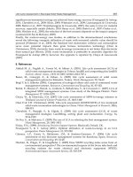
If rock bolts are desired to be a permanent system of support, all boltholes must be
grouted completely with cement grout (Fig. 12.4a) or resin. This is for preserving the pre-
tension and preventing corrosion of steel. (Steel ribs are also encased in concrete lining
for the same reasons.) For this purpose either an air tube or hollow bar of high strength
is used. While grouting a bolt, the rubber grout seal is used to center the bolt in the hole
and to seal the collar of the hole against grout leakage. Grout injection is stopped when
air has been displaced and the grout flows out from the return tube (Fig. 12.4a). A site
engineer should check the flowing out of return grout to ensure the full-column grouting
of rock bolts.
Resin
cartridges
25 mm
Rebar
19 mm dia
32 mm
38 mm
Split
perforated
tubes filled
with cement
mortor
Cement
Rebar
25mm dia
Anchorage
Cement
Grout
Air out
Grout in
a. Grouted Point-Anchored Bolt
b. Perfo Bolt
c. Resin Bolt
Fig. 12.4 Process of installation of grouted bolts.
Rock bolting 187
In situation where very long bolts are required such as in large underground chambers
(and high slopes), a steel cable may be substituted for steel bar.
The full-column grouted bolts without pre-tension are also quite effective in reinforc-
ing the rock masses as mentioned earlier. In civil engineering construction, “Perfobolts”
are used to provide a permanent system of support. It consists of a pair of semi-cylindrical
perforated metallic tubes which are filled with cement mortar and tied with wire and
inserted into the borehole. Then a steel bolt of a slightly smaller diameter is hammered
into the tube as shown in Fig.12.4b. The mortar extrudes evenly out of perforations and
fills the borehole. The modern trend is towards using resin grout because time of attaining
full strength of resin is just 5 min compared to 10 h for cement. The “resin bolts” are more
popular in mines and tunnels in Europe. First, resin cartridges (sausages) are inserted with
the bolt and pushed to the end of the borehole. The bolt is then rotated at 100–600 rpm
for about 10 s to break the cartridge and mix its contents, i.e., the polyester resin, catalyst
and hardener (Fig. 12.4c). The bearing plate and the nut are fitted to suspend any loose
rock mass at the rock surface because the resin may not ooze right down to the bottom of
the borehole. It may be noted here that the grouted bolts are slightly costlier than point-
anchored bolt, as such they are used in highly unstable (or rock burst prone) grounds or
where a permanent system of support is required.
The fast rotating cartridge may dig up weak rock layers locally, preventing thorough
mixing of resin in long bolts. So, bolt length should be less than 5 m in poor rocks. It is
cautioned that the resin has limited shelf life in hot climates. Therefore, this must be
checked before its application.
Some other types of bolts, e.g., pins driven hydraulically into soft rocks (Harrell,
1971) and roof trusses developed by Birmingham Bolt Co. (Kmetz, 1970) and explosively
expanded rock bolts developed by U.S. Bureau of Mines are not commonly used.
Hoek and Brown (1980) have presented an excellent summary of new types of rock
bolts. Of special interest is split tube anchor which is popular in mines where temporary
stability is all that is needed. The bolt consists of 2–3 mm thick and 38 mm diameter split
tube with 13 mm gap (Fig. 12.5). It is forced into a 35 mm diameter drillhole. The spring
13 mm
38 mm
Fig. 12.5 Split set tube bolt.
188 Tunnelling in weak rocks
action of the tube causes the tube to jam inside the hole. The friction between drillhole and
tube is increased as bolt is rusted. Grouting of this type of bolt is not possible. Rusting of
split tube bolts occurs rapidly and therefore anchorage increases with time. It is difficult
to install long split tube bolts.
Fig. 12.6 shows a collapsed tube called swellex bolt. It is inserted into the bore hole
and expanded by air and water pressure to the shape of bore hole. The friction between
tube bolt and rock reinforces the rock mass. It is ideally suited in supporting tunnels within
water-charged rock masses where grouting by cement or resin is not feasible. Corrosion
can be a long-term problem both in the split tube and swellex bolts.
12.3 SELECTION OF ROCK BOLTS
Following guidelines may prove useful in selection of bolts (Pender et al., 1963),
(i) Deformed bar shanks are now used for all bolts which are to be grouted with
cement or resin. They are installed along unsupported free length near the tunnel
face within the bridge action period of rock mass.
(ii) Plain shank bolts are used only for temporary full-column grouted bolts support or
where concrete lining is to be placed for permanent support. The modern practice is
Fig. 12.6 Swellex tube bolt (Hoek, 2004).
Rock bolting 189
to recommend thermo-mechanically treated (TMT) bolts as they are ductile having
strength of 415 MPa (against 250 MPa of mild steel).
(iii) Bolts of high tensile strength should be used with precaution. When it breaks, it
leaves a hole with high velocity. In squeezing ground or where rock bursts are
likely, mild steel bolts are preferred because it meets the requirement of large
plastic yielding. Special yieldable head type bolts may also be used in squeezing
conditions (Barla, 1995).
(iv) The cement grout should be designed properly for flowability, slight expansion
on hardening and high shear strength. These properties are obtained with grouts
having water cement ratio between 0.38 and 0.44 to which commercial aluminum
powder has been mixed in amounts up to 0.005 percent by weight of cement.
Excessive aluminum powder may create weak, spongy and powdery grout. Other
expanding agents may also be used as per specifications of manufacturers.
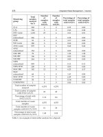
Mandal (2002) has suggested rock bolt and shotcrete support systems for various
tunnelling ground conditions as given in Table 12.1.
Table 12.1 Suggested support for various rock conditions (Mandal, 2002).
Rock conditions Suggested support type
Sound rock with smooth walls
created by good blasting. Low in
situ stresses.
No support or alternatively, where required for safety,
mesh held in place by grouted dowels or mechanically
anchored rock bolts, installed to prevent small pieces
from falling.
Sound rock with few intersecting
joints or bedding planes resulting
in loose wedges or blocks. Low in
situ stresses.
Scale well; install tensioned, mechanically anchored bolts
to tie blocks into surrounding rock, use straps across
bedding planes or joints to prevent openings. Such as in
shaft stations or crusher chambers, rock bolts should be
grouted with cement to prevent corrosion.
Sound rock, damaged by blasting,
with few intersecting weakness
planes forming blocks and
wedges. Low in situ stress
conditions.
Chain link or weld mesh, held by tensioned mechanically
anchored rock bolts, to prevent falls of loose rock.
Attention must be paid to scaling and to improving
blasting to reduce amount of loose rock.
Closely jointed blocky rock with
small blocks ravelling from
surface causing deterioration if
unsupported. Low stress
conditions.
Shotcrete layer, approximately 50 mm thick. Addition of
micro-silica and steel fiber reduces rebound and
increases strength of shotcrete in bending. Larger
wedges are bolted so that shotcrete is not overloaded.
Limit scaling to control ravelling. If shotcrete not
available, use chain link or weld mesh and pattern
reinforcement such as split sets or swellex.
Continued
190 Tunnelling in weak rocks
Table 12.1—Continued
Stress-induced failure in jointed
rock. First indications of
failure due to high stress are
seen in borehole walls and in
pillar corners.
Pattern support with grouted dowels. Split sets are suitable for
supporting small failures. Grouted tensioned or unten-
sioned cable can be used but mechanically anchored rock
bolts are less suitable for this application. Typical length of
reinforcement should be about half the span of openings
less than 6 m and between half and one-third for spans of 6
to 12 m spacing should be installed before significant move-
ment occurs. Shotcrete can add significant strength to rock
and should be used in long-term openings (drill-drive etc.)
Drawpoints developed in good
rock but subjected to high
stress and wear during blasting
and drawing of stopes.
Use grouted rebar for wear resistance and for support of
drawpoints brows. Install this reinforcement during
development of the trough drives and draw point, before
rock movement takes place as a result of drawing of stopes.
Do not use shotcrete or mesh in drawpoints. Place dowels
at close spacing in blocky rock.
Fractured rock around openings
in stressed rock with a
potential of rock bursts.
Pattern support required but in this case some flexibility is
required to absorb shock from rock bursts. Split sets are
good since they will slip under shock loading but will still
retain some load and keep mesh in place. Grouted resin
bolts and Swellex will also slip under high load but some
face plates may fail. Mechanically anchored bolts are poor
in these conditions. Lacing between heads of reinforcement
helps to retain rock near surface under heavy rock bursting.
Very poor quality rock
associated with faults or shear
zones. Rock bolts or dowels
cannot be anchored in this
material.
Fiber-reinforced shotcrete can be used for permanent support
under low stress conditions or for temporary support to
allow steel sets to be placed. Note that shotcrete layer must
be drained to prevent build up of water pressure behind the
shotcrete. Steel sets are required for long-term support
where it is evident that stresses are high or that rock is
continuing to move. Capacity of steel sets estimated from
amount of loose rock to be supported. Min. 200 mm
backfilling is required to develop contact between steel sets
and rock surface.
12.4 INSTALLATION OF ROCK BOLTS
12.4.1 Scaling
One of the most frequent causes of accidents in underground excavations is indequate
scaling soon after blasting. Scaling work consists of removal of loose pieces of rock from
roof and walls before workmen move towards the face of excavation. It is generally done
Rock bolting 191
manually by using long steel bars. The sound of impact of a steel bar on the rock may
tell the foremen whether or not the rock is loose. The same is then removed. However,
there is poor visibility and walls are covered with dust and face is not easily accessible,
so manual scaling may not be very much effective.
12.4.2 Installation
The rock bolts must be installed as soon as possible after scaling and within bridge action
period. The delay in installation may not only jeopardize the safety of workmen due to
greater chances of rock fall but it also reduces the strength of the rock mass. The good
practice is:
(i) Install rock bolts concurrently with drilling of blast-holes in the (tunnel or mine)
face for the next round using common jumbo. The experience is that the bolts
even close to the face are seldom damaged after blasting, except that there is
loss of pre-tension. The grouting may then be done if required. The grout-
ing facilities (e.g., inlet and outlet tubes in Fig. 12.4a) should be provided at
the time of rock bolting so that pre-tension in the bolt is not released while
grouting.
(ii) The loosened rock particles in the roof should be pulled down rather than bolted.
Scaling reduces the need for spot bolting.
(iii) Thorough inspection of the rock mass (key blocks) should be done before bolting
to locate the weak zones that require special treatment or spot bolting.
12.4.3 Pre-tensioning
For efficient use of the point-anchored bolts, the pre-tension (P) must be as high as the bolt
can take safely. To avoid overstressing of the bolt, adjustable automatic-cutoff (hydraulic
driven or impact) torque wrenchesshould be used to apply the desired torque (T) on the nut.
For purpose of checking the pre-tension, manually operated (lever type) torque wrenches
with dial may be used. Experiences show that the greased hard nut should be used above
the torque nut in order to increase the tension torque ratio (P/T) and to minimize the
scatter in this ratio (Osen & Parsons, 1966; Agapito, 1970). The typical tension–torque
relationship is given by
T = KPd (12.1)
where d is nominal diameter of a bolt and K is a constant (
∼
=
0.20). Thus the bolt may
fail due to combined stresses of tension and torque. To increase torque limit, bolts of
high tensile steel are used for bolt diameter of 19 mm or less (in expansion shell). But in
soft rocks, mild steel bolts are strong enough. Very often in the field, bolts of too large
diameter tend to be used for psychological reasons in the poor rocks, though they cannot
provide much anchorage capacity.
192 Tunnelling in weak rocks
There is no need of tensioning full-column grouted bolts in the weak zones (Tincelin,
1970), and in fact too high pre-tension might reduce the efficiency of bolts. However, a
resin bolt may be pre-tensioned by first inserting cartridge of fast setting resin, followed
by cartridges of slow setting resin and thereafter rotating the bolt, and finally tightening
the torque nut as for the point-anchored bolt.
12.4.4 Wiremesh
If the clear spacing between bearing plates is too large compared to the fracture spacing,
rock blocks are likely to fall down leading to complete collapse of the bolted roof. The wire
mesh has proved more successful than initially thought of in preventing such spalling and
ravelling of highly fractured rock masses. However, the wire mesh should be stretched
tightly between rock bolts and held close to the rock surface. Further it also provides an
effective protection to the workmen against rock falls. Infact, even a flimsy wire netting
serves the structural purpose.
Chain link mesh is used when spacing between bolts is considerable and mesh is
required to hold small pieces of rock which become detached from the roof due to the
poor work of scaling. This type of wire mesh consists of a woven fabric of wire such as
mesh for fencing around play grounds. It is flexible. It is easy for shotcrete to penetrate
behind the chain link mesh. The contact between rock surface and mesh is a difficult task in
practice. Since wire mesh is easily damaged by flying pieces of rock from the nearby blast,
it has been suggested (Hoek & Bray, 1980) that the mesh should not be fixed right upto face.
Another type of wire mesh is weld mesh which is generally used for reinforcing
shotcrete. It consists of a square grid of steel wires, welded at junctions.
12.4.5 Rock bolt ties
In addition, continuous steel ties are also employed to support the unstable rock mass.
The ties may be of steel channel sections with properly spaced holes for the bolts.
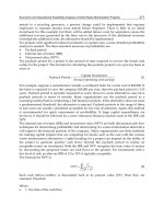
12.5 PULL-OUT TESTS
Pull-out tests on certain percentage of bolts are necessary to (i) measure the residual pre-
tension in bolts after blasting, (ii) check their anchorage capacity and (iii) study creep
effect, etc.
Fig. 12.7a illustrates a typical pull-out test as suggested by Franklin and Woodfield
(1971). The bolt is pulled out by a 100 ton spring-return hollow ram with low friction seals
for reproducible calibration. The ram is pressurized by a hand pump connected through
a high pressure flexible hose. The pull is measured by a pressure gauge calibrated directly
in tons. The movement of the bolt-head which is the sum of anchor slip and deformations
in bolt can be monitored easily by a set of dial gauges. The bolt should be tested for a
movement to the extent of 5 to 8 cm in order to study the post-failure behavior.
Rock bolting 193
Spherical
Seat
Nut
Magneti
c
Clamp
Nut
Measuring
Beam
Piston
Dial
Gauge
Base Plate
To Pump and
Pressure Gauge
Resin or
Mechanical Anchor
Ram
Fig. 12.7a Rock bolt testing equipment (Franklin and Woodfield, 1971).
To measure actual tension, an auxiliary shank may be coupled to the bolt-head. It
is pulled out by the ram which rests on an extra packer over a bearing plate to accom-
modate the coupling. The actual tension is that load at which torque nut just looses
contact with the bearing plate. The International Society for Rock Mechanics (ISRM)
has also suggested a method for pull-out test on rock anchors and bolts. Sometimes
the quality of grout is checked by overcoring a 15 cm diameter core containing the
rock bolt.
Typical test results are shown in Fig. 12.7b. It is seen that mechanical anchorages
may slip upto 50 mm before peak load in contrast to only 5 mm for resin bolts. In addition
resin bolts are found to give much better anchorage capacity.
The quality of bolts should also be checked in laboratory by testing five bolts per 1000
according to the suggested method of ISRM (1981) as follows:
(i) Tensile test on anchorage
(ii) Tensile test on nut and bearing plate
194 Tunnelling in weak rocks
0 1.0 2.0 3.0 0 1.0 2.0 3.0
0
1000
2000
3000
RESIN ANCHORS
Max. Bolt Strength
0
10
20
30
Short Tons Load
(a)
(b)
Bolt Extension, inch. Bolt Extension, inch.
0
1000
2000
3000
Max. Bolt Strength
Yield Strength
Yield Strength
MECHANICAL ANCHORS
0
10
20
30
Short Tons Load
Jack Pressure, psi
Jack Pressure, psi
Bolt De-
formation
Bolt De-
formation
Fig. 12.7b Pull-out curves for granites (a) resin-anchored bolts, (b) mechanically anchored bolts.
(iii) Tensile test on the shank
(iv) Test for determining torque–tension ratio
Fairhurst and Singh (1974) conducted model tests on a bolted model of four layers
(simply supported at the ends) to compare the reinforcement action of full-column grouted
bolts and point-anchored bolts. Plexiglass beams and Masonite beams were used to repre-
sent brittle layers and ductile layers of rock masses. Both have practically same values of
modulus of elasticity and modulus of rupture. The generally low stiffness of mechanically
anchored bolt was modelled by interposing a spring between nut at the top end of each bolt
and pre-tensioning the spring to exert on average pressure of 0.07 MPa across the layer.
The grouted bolt consisted of 3 mm diameter steel rod in 5 mm hole filled with epoxy.
Fig. 12.8 compares the normalized force and deflection curves for various models. It is
seen that grouted bolts performed better than point-anchored bolt. This is also borne out
by the field experience. Panek’s (1955a, b, 1961, 1962) suspicion on efficacy of grouted
bolts is not based on reality.
It is interesting to note that a fracture occurred through the grouted bolt in the Plexiglas
beam presumably because of stress concentration around the bolthole. Consequently the
grouted bolts lowered the ultimate load carrying capacity of the brittle beam. On the other
hand the more ductile Masonite beam yielded around boltholes rather than fracturing as
in the case of Plexiglas beam. Tests on thick beams of Plexiglas however exhibited the
elasto-plastic shearing through bolt without any fracturing of the beam. A study of the
computer model of bolted layers was taken up (Singh et al., 1973) to verify the prediction.
Rock bolting 195
Grouted
Point Anchored
0
1.0
1.5
Center Deflection, Inch.
0.0
0.25
0.50
0.75
1.0
Center Deflection, Inch.
2.0
0.5
Unbolted
Fracture
F
Fracture through
Bolt Hole
F
Point Anchored
Unbolted
Grouted
F = Normalized Force, [F = F
applied
/F
max
, unbolted]
a. Masonite Beams
b. Plexiglas Beams
0 0.2 0.4 0.6 0.8 1.0 1.2
0 0.2 0.4 0.6 0.8 1.0 1.2
Fig. 12.8 Load deflection results from model rock bolting tests (Fairhurst and Singh, 1974).
It was shown that the untensioned grouted bolt (at usual spacing) makes a rock beam
almost monolithic in behavior.
12.6 REINFORCEMENT OF JOINTED ROCK MASS AROUND OPENINGS
12.6.1 Reinforced beam
According to Lang (1961), axial pre-stress is developed due to Poisson’s effect of
normal stress on account of bolt’s pre-tension. This pre-stress can stabilize the rock beam
effectively as in the case of pre-stressed concrete beam.
196 Tunnelling in weak rocks
A two-dimensional photoelastic study showed that the pre-tension of bolts form a
zone of uniform compression between the ends of the bolts (Fig. 12.9). The only condition
is that the ratio between length (l) and spacing (s) of bolts is more than 2. At this ratio,
the zone is relatively narrow whereas for l/s equal to 3, it is approximately equal to two-
third of the bolt length (i.e., equal to l−s). The normal stress (σ
v
) within the zone may
be estimated as ratio of pre-tension to the area per bolt. The horizontal stress (σ
h
) equal
to k
o
σ
v
would be induced within this zone provided that the bolted beam is clamped
laterally.
(b) l/s = 2.0
Tension
l
(a) l/s = 1.5
s
Zone of Uniform
Compression
Tension
(c) l/S = 3.00
Fig. 12.9 Rock bolt – photoelastic stress pattern (Lang, 1961).
Rock bolting 197
The total horizontal force is the sum of axial pre-stress (P
h
) and the thrust (T) due
to the arch action. Higher horizontal force means greater frictional resistance to sliding
of the beam downwards.
The photoelastic model further indicated that zones of tensile stresses develop between
bolts and so it may require an additional support in the form of wire-netting.
Large scale model tests to demonstrate the effectiveness of pre-tensioned bolts were
also performed by Lang (1966). Crushed rock material of 38 to 57 mm in size was filled
in a box of 1.2 m ×1.2 m ×1.2 m, compacted by vibration and then bolted with 58 cm
long bolts. The reinforced rock mass was loaded at the center. At a load of 7000 1b (point
D in Fig. 12.10), rock fragments started falling out leading to failure. The strength of
the beam was almost doubled when the experiment was repeated using 24 gauge chicken
wire net placed securely under the bolt-washers but not attached to the sides of the box.
Note that repeated loading caused plastic deformations but without failure. This is because
of some loss of pre-tension in bolts due to re-adjustment of rock fragments. Hence, the need
for retightening of the bolts after vibrations or repeated loading. It was also demonstrated
that only a very flimsy support is needed to hold the loose material within the tension
zone between the bolt-washers.
If the clear spacing between the washer was less than 3 to 4 times the mean particle
size, wire mesh was not required to prevent the ravelling as mentioned above. If this
ratio was less than 7, the particles fell out between bolts but eventually a stable vault was
formed. If this ratio was greater than 7, a fall out (ravelling) continued leading to total
collapse. Similar conclusions have been made by Coates (1970) for block jointed models
of rock mass with different orientations of joint sets.
2000
4000
6000
8000
10000
12000
14000
+++
+++
+++
PP
δ
Bolting Pattern
Section of Box
11
7
9
8
5
6
4
3
1
2
D
A
10
0
0 0.1 0.2 0.3 0.4 0.5 0.6
S
2
S
1
W
l
Vertical Displacement - Center of Box ‘δ’ inch
Central Vertical Load (W)
Fig. 12.10 Behavior of crushed rock model (Lang, 1961) [Rock size range was 1-1/2’ to 2-1/4’;
The mean (m) was 1.875 inch (F = S
2
/m = 4.3)].
198 Tunnelling in weak rocks
An experiment may be conducted at home by filling a bucket with crushed rock which
is then bolted with single pre-tensioned bolt. The bucket is then turned upside down to
see whether rock mass has been stabilized.
12.6.2 Reinforced rock arch
It may be seen from Fig. 12.11 that radial bolting pattern creates a reinforced rock arch
over the tunnels. The thickness of an arch can be increased by employing supplementary
bolts of shorter length. The most common practice is (Lang, 1966; Barton et al., 1974)
(i) Rock bolts should be pre-tensioned to give required ultimate support capacity
(p
roof
or p
wall
) which is equal to P/b·s where P = pre-tension, b = bolt spacing
20′
7 Bolts each 20′ long, spaced 6′x6′
11 Bolts each 8′ long, spaced 4′x4′
7 Bolts each 16′ long, spaced 5-1/2′ x 5-1/2′ 9 Bolts each 8′ long, spaced 4′x4
′
20′
24′
24′
Fig. 12.11 Arch concept of rock reinforcement in circular and horse-shoe shaped tunnels
(Lang, 1961).
Rock bolting 199
along tunnel axis and s =bolt spacing perpendicular to the tunnel axis. The pre-
tensioned bolts are suitable for temporary support of openings in the hard rocks.
(ii) Grouted bolt anchors should be designed to provide ultimate support pressure
(p
roof
or p
wall
) equal to P/bs where P is the tensile strength of bolts, provided
bolts are adequately grouted. The bolt length should be greater than 1/4 to 1/3 of
span of the tunnel.
(iii) The length of bolts (L in meters) should be calculated from the following simple
relationship given by Barton et al. (1974),
L = 2 + (0.15 B/ESR) for roof (12.2)
= 2 + (0.15 H/ESR) for wall (12.3)
where
B = span or width of opening in meters,
H = height of opening wall in meters and
ESR = excavated support ratio (Table 5.11).
(iv) The adequate length of grouted anchors be obtained similarly as follows,
L = 0.40 B/ESR for roof (12.4)
= 0.35 H /ESR for wall (12.5)
(v) When single (2–3 cm thick) or double (5 cm thick) layers of shotcrete are applied
usually in combination with systematic bolting, the function of shotcrete is to
prevent loosening, especially in the zone between bolts. The capacity of shotcrete
lining is, therefore, neglected. The application of shorcrete is essential to make
grouted bolt–anchor system as permanent support.
(vi) Clear spacing between bolts should not be more than three times the average
fracture spacing otherwise use wire mesh and guniting or shotcreting. Further
center to center spacing must be less than one-half of the bolt length.
(vii) Bolts are installed on a selected pattern except near weak zones that would require
special treatment. Spot bolting should be discouraged.
(viii) Bolts should be oriented to make an angle of 0 to φ to the normal on the critical
joint sets in order to develop maximum resistance along joints (Fig. 12.12).
(ix) Bolts must be installed as early as possible within “Bridge Action Period” and
close to the excavated face (Fig. 4.1).
However a tunnel is always unsupported in a certain length “t” between the last row
of bolting and the newly excavated face (blasted face). Suppose rock is pulled out to a
length of 3 m in each round of blasting, one may then assume the unsupported length (t)
to be about 4 m. According to Rabcewicz (1955), the zone of rock mass of thickness of
t/2 may be fractured and loosened due to blasting as shown in Fig. 12.13. Thus the bolt
200 Tunnelling in weak rocks
A. Horizontal joint system B. Inclined joint system
C. Vertical
j
oint s
y
stem
Fig. 12.12 Roof bolting in strata having various dip angles.
Limit of
Loosening
Natural Arch Created
by Bolting
Y
Y
t/2
h
b
t/2
t
X
X
l
Limit of
Loosening
Gunite
Section Y-Y Section X-X
Fig. 12.13 Diagrammatic sections demonstrating principles of roof bolting.
Rock bolting 201
length must be at least equal to the thickness of loosened zone (= t/2), so that the loose
zone may be suspended by competent rock mass.
Rock bolts/anchors should be designed to absorb high longitudinal strains in the cases
of weak rock masses. So the bolts of high tensile strength are failure in caverns and tunnels
in weak rocks under high tectonic stresses, as in Tala Hydroproject, Bhutan (Singh, 2003).
12.7 BOLTING PATTERN
It is generally agreed that pattern bolting should be preferred over spot bolting because
unknown conditions behind the surface of an excavation may be more critical than those
visible at the surface. In addition, pattern bolting is advantageous from construction point
of view also.
12.8 FLOOR BOLTING
Floor bolting is required to prevent floor of a tunnel from heaving in order to maintain the
track properly for efficient haulage. Attempts to chop off squeezed rock mass are fruitless
and may damage the wall support. The experience is that reinforcement of rock mass in
the floor by rock bolts is very effective. However there is no standard practice. If swelling
soft shale is found in the floor of a deep tunnel opening heaving may be serious.
In squeezing ground, rock bolting is not enough. It is important to apply steel fiber
reinforced shotcrete (SFRS) layer by layer around the opening. It is necessary that invert
of shotcrete lining is also laid so that it may enable the shotcrete walls to take heavy wall
pressures. But one must understand the tunnelling hazards.
REFERENCES
Agapito, J. (1970). Development of a better rock-bolts assembly at White Pine. presented AIME
Annual Meetings Denver, Colorado, February 15-19, 1970. Preprint No. 70 - AM - 87.
Barla, G. (1995). Squeezing Rocks in Tunnels, ISRM News Journal, 2 (3 & 4), 44-49.
Barton, N., Lien, R. and Lunde, J. (1974). Engineering classification of rock masses for design of
tunnel support, Rock Mechanics, 6, 189-236.
Coates, D. F. (1970). Rock Mechanics Principles, Mines Branch Department of Energy and
Resources, Canada, Mines Branch Monograph 874, Art 3.29, 7.15.
Fairhurst, C. and Singh, B. (1974). Roof bolting in horizontally laminated rock, Engineering and
Mining Journal, Feb. 80-90.
Franklin, J. A. and Woodfield, P. F. (1971). Comparison of a polyester resin and a mechanical rock
bolt anchor. Inst. Min. Met. Trans, Sec. A Mining Industry, London, 80(776), 91-100.
202 Tunnelling in weak rocks
Harrell, M. V. (1971). Roof control with hydraulically driven pins. Mining Congress Journal, July
1971, 27-31.
Hoek, E. and Brown, E. T. (1980). Underground Excavations in Rock. The Institution of Min. Met.,
London Chap. 9.
Hoek, E. and Bray, J. W. (1981). Rock Slope Engineering. The Inst. Min. Met, 3rd edition, Chap. 7
and Appendix III.
Hoek, E. (2004). Downloaded from Internet.
ISRM (1981). Suggested methods for rock bolt testing. Rock Characterization Testing and
Monitoring, Ed: E.T. Brown, 163-168.
Kmetz, W. J. (1970). Roof trusses support problem strata. Coal Age, Jan. 1970, 64-68.
Lang, T. A. (1961). Theory and Practice of Rock Bolting. A.I.M.E., Trans., 220.
Lang, T. A. (1966). Theory and practice of rock reinforcement. 45
th
Annual Meetings Highway
Research Board, Washington D.C.
Mandal, K. S. (2002). Temporary support methods - an overview. Indian Rock Conference, ISRMTT,
New Delhi, India, 296-319.
Osen, L. and Parsons, E. W. (1966). Yield and Ultimate Strengths of Rock Bolts under Combined
Loading. U.S. Bureau of Mines, R.I. 6842.
Panek, L. A. (1955a). Principles of Reinforcing Bedded Roof with Bolts. U.S. Bureau of Mines,
R.I. 5156.
Panek, L. A. (1955b). Design of Bolting Systems to Reinforce Bedded Mine Roof. U.S. Bureau of
Mines, R.I. 5155.
Panek, L. A. (1961). The Combined Effect of Friction and Suspension in Bolting Bedded Mine roof.
U.S. Bureau of Mines, R.I. 6139.
Panek, L. A. (1962). The Effect of Suspension in bolted Bedded Mine Roof. U.S. Bureau of Mines,
R.I. 6138.
Pender, E. B., Hosking, A. D. and Mattner, R. H. (1963). Grouted Rock Bolts for Permanent
Support of Major Underground Works. Inst. of Engrs. Australia Journal, Sydney, 35,
(7-8), July-Aug-1963, 129-150.
Rabeewiez, L. V. (1955). Bolted support for tunnels. Mine and Quarry Engineering, Part I,
March 1955, 111-116, Part II, April 1955, 153-160.
Singh, B., Fairhurst, C. and Christiano, P. P. (1973). Computer simulation of laminated roof
reinforced with grouted bolts. I.G.S. Symp. Rock Mechanics and Tunnelling Problems,
Kurukshetra, 41-47.
Singh, R. B. (2003). Personal Communication with Bhawani Singh, IIT Roorkee, India.
Tincelin, E. (1970). Roof bolting recommendations, Publication of Parley of Cooperation and
Industrial Promotion for Exploration and Exploitation of Mineral Deposits and Mineral
Processing, Sydney, 26-27 May, 1970.
13
Tunnelling hazards
“The most incomprehensible fact about nature is that it is comprehensible.”
Albert Einstein
13.1 INTRODUCTION
The knowledge of potential tunnelling hazards plays an important role in the selection
of excavation method and designing a support system for underground openings. The
tunnelling media could be stable/competent (and or non-squeezing) or squeezing/failing
depending upon the in situ stress and the rock mass strength. A weak over-stressed rock
mass would experience squeezing ground condition (Dube & Singh, 1986), whereas a
hard and massive over-stressed rock mass may experience rock burst condition. On the
other hand, when the rock mass is not over-stressed, the ground condition is termed as
stable or competent (non-squeezing).
Tunnelling in the competent ground conditions can again face two situations – (i)
where no supports are required, i.e., a self-supporting condition and (ii) where supports
are required for stability; which is a non-squeezing condition. The squeezing ground
condition has been divided into four classes on the basis of tunnel closures by Hoek (2001)
as minor, severe, very severe and extreme squeezing ground conditions (Table 13.1).
The worldwide experience is that tunnelling through the squeezing ground condition
is a very slow and hazardous process because the rock mass around the opening loses its
inherent strength under the influence of in situ stresses. This may result in mobilization
of high support pressure and tunnel closures. Tunnelling under the non-squeezing ground
condition, on the other hand, is comparatively safe and easy because the inherent strength
of the rock mass is maintained. Therefore, the first important step is to assess whether a
tunnel would experience a squeezing ground condition or a non-squeezing ground condi-
tion. This decision controls the selection of the realignment, excavation method and the
support system. For example, a large tunnel could possibly be excavated full face with
light supports under the non-squeezing ground condition. It may have to be excavated by
Tunnelling in Weak Rocks
B. Singh and R. K. Goel
© 2006. Elsevier Ltd
204 Tunnelling in weak rocks
Table 13.1 Classification of ground conditions for tunnelling (Singh & Goel, 1999).
S.No.
Ground
condition
class Sub-class Rock behavior
1. Competent self-
supporting
– Massive rock mass requires no support
for tunnel stability
2. Incompetent
non-
squeezing
– Jointed rock mass requires supports for
tunnel stability. Tunnel walls are
stable and do not close
3. Ravelling – Chunks or flakes of rock mass begin to
drop out of the arch or walls after the
rock mass is excavated
4. Squeezing Minor squeezing
(u
a
/a =1–2.5%)
Severe squeezing
(u
a
/a =2.5–5%)
Very severe squeezing
(u
a
/a =5–10%)
Extreme squeezing
(u
a
/a>10%)
(Hoek, 2001)
Rock mass squeezes plastically into the
tunnel both from the roof and the
walls and the phenomenon is time
dependent; rate of squeezing depends
upon the degree of over-stress; may
occur at shallow depths in weak rock
masses like shales, clay, etc.; hard
rock masses under high cover may
experience slabbing/popping/rock
burst
5. Swelling – Rock mass absorbs water, increases in
volume and expands slowly into the
tunnel (e.g., in montmorillonite clay)
6. Running – Granular material becomes unstable
within steep shear zones
7. Flowing/sudden
flooding
– A mixture of soil like material and
water flows into the tunnel. The
material can flow from invert as well
as from the face crown and wall and
can flow for large distances
completely filling the tunnel and
burying machines in some cases. The
discharge may be 10–100 l/s which
can cause sudden flood. A chimney
may be formed along thick shear
zones and weak zones.
8. Rock burst – A violent failure in hard (brittle) and
massive rock masses of Class II*
type when subjected to high stress
Notations: u
a
= radial tunnel closure; a = tunnel radius; u
a
/a = normalized tunnel closure in percentage; * UCS
test on Class II type rock shows reversal of strain after peak failure.
Tunnelling hazards 205
heading and benching method with a flexible support system under the squeezing ground
condition.
Non-squeezing ground conditions are common in most of the projects. The squeezing
conditions are common in the Lower Himalaya in India, Alps and other young moun-
tains of the world where the rock masses are weak, highly jointed, faulted, folded and
tectonically disturbed and the overburden is high.
13.2 THE TUNNELLING HAZARDS
Various tunnelling conditions encountered during tunnelling have been summarized in
Table 13.1. Table 13.2 suggests the method of excavation, the type of supports and
precautions for various ground conditions. Table 13.3 summarizes different conditions
for tunnel collapse caused by geological unforeseen conditions, inadequacy of design
models or support systems (Vlasov et al., 2001).
Commission on Squeezing Rocks in Tunnels of International Society for Rock
Mechanics (ISRM) has published Definitions of Squeezing as reproduced here
(Barla, 1995).
“Squeezing of rock is the time dependent large deformation, which occurs around a
tunnel and other underground openings, and is essentially associated with creep caused
by (stress) exceeding shear strength (limiting shear stress). Deformation may terminate
during construction or continue over a long time period.”
This definition is complemented by the following additional statements:
• Squeezing can occur in both rock and soil as long as the particular combination
of induced stresses and material properties pushes some zones around the tunnel
beyond the limiting shear stress at which creep starts.
• The magnitude of the tunnel convergence associated with squeezing, the rate of
deformation and the extent of the yielding zone around the tunnel depend on the
geological conditions, the in situ stresses relative to rock mass strength, the ground
water flow and pore pressure and the rock mass properties.
• Squeezing of rock masses can occur as squeezing of intact rock, as squeezing of
infilled rock discontinuities and/or along bedding and foliation surfaces, joints and
faults.
• Squeezing is synonymous of over-stressing and does not comprise deformations
caused by loosening as might occur at the roof or at the walls of tunnels in jointed
rock masses. Rock bursting phenomena do not belong to squeezing.
• Time-dependent displacements around tunnels of similar magnitudes as in squeezing
ground conditions, may also occur in rocks susceptible to swelling. While swelling
always implies volume increase due to penetration of the air and moisture into the
rock, squeezing does not, except for rocks exhibit a dilatant behavior. However,
it is recognized that in some cases squeezing may be associated with swelling.
Table 13.2 Method of excavation, type of supports and precautions to be adopted for different ground conditions.
S.No
Ground
conditions Excavation method Type of support Precautions
1. Self-supporting/
competent
TBM or full face drill
and controlled blast.
No support or spot bolting with a thin layer of
shotcrete to prevent widening of joints.
Look out for localized wedge/shear zone.
Past experience discourages use of TBM
if geological conditions change
frequently.
2. Non-squeezing/
incompetent
Full face drill and
controlled blast
by boomers.
Flexible support; shotcrete and
pre-tensioned-rock-bolt supports of required
capacity. Steel fiber reinforced shotcrete (SFRS)
may or may not be required.
First layer of shotcrete should be applied
after some delay but within the stand-up
time to release the strain energy of rock
mass.
3. Ravelling Heading and bench;
drill and blast
manually.
Steel support with struts/pre-tensioned rock bolts
with steel fiber reinforced shotcrete (SFRS).
Expect heavy loads including side pressure.
4. Minor
squeezing
Heading and bench;
drill and blast.
Full column grouted rock anchors and SFRS. Floor
to be shotcreted to complete a support ring.
Install support after each blast; circular
shape is ideal; side pressure is expected;
do not have a long heading which delays
completion of support ring.
5. Severe
squeezing
Heading and bench;
drill and blast.
Flexible support; full column grouted highly ductile
rock anchors and SFRS. Floor bolting to avoid
floor heaving & to develop a reinforced rock
frame. In case of steel ribs, these should be
installed and embedded in shotcrete to withstand
high support pressure.
Install support after each blast; increase the
tunnel diameter to absorb desirable
closure; circular shape is ideal; side
pressure is expected; instrumentation is
essential.
6. Very severe
squeezing
and extreme
squeezing
Heading and bench in
small tunnels and
multiple drift
method in large
tunnels; use
forepoling if
stand-up time is low.
Very flexible support; full-column grouted highly
ductile rock anchors and thick SFRS; yielding
steel ribs with struts when shotcrete fails
repeatedly; steel ribs may be used to supplement
shotcrete to withstand high support pressure; close
ring by erecting invert support; encase steel ribs in
shotcrete, floor bolting to avoid floor heaving;
sometimes steel ribs with loose backfill are also
used to release the strain energy in a controlled
manner (tunnel closure more than 4 percent shall
not be permitted).
Increase the tunnel diameter to absorb
desirable closure; provide invert support
as early as possible to mobilize full
support capacity; long-term
instrumentation is essential; circular
shape is ideal.
7. Swelling Full face or heading
and bench; drill and
blast.
Full-column grouted rock anchors with SFRS shall
be used all-round the tunnel; increase 30 percent
thickness of shotcrete due to weak bond of the
shotcrete with rock mass; erect invert strut. The
first layer of shotcrete is sprayed immediately to
prevent ingress of moisture into rock mass.
Increase the tunnel diameter to absorb the
expected closure; prevent exposure of
swelling minerals to moisture, monitor
tunnel closure.
8. Running and
flowing
Multiple drift with
forepoles; grouting
of the ground is
essential; shield
tunnelling may be
used in soil
conditions.
Full column grouted rock anchors and SFRS;
concrete lining up to face, steel liner in exceptional
cases with shield tunnelling. Use probe hole to
discharge ground water. Face should also be
grouted, bolted and shotcreted.
Progress is very slow. Trained crew should
be deployed. In case of sudden flooding,
the tunnel is realigned by-passing the
same. Monitor rate of flow of seepage.
9. Rock burst Full face drill and blast Fiber reinforced shotcrete with full column resin
anchors immediately after excavation.
Micro-seismic monitoring is essential.
Table 13.3 Quality aspects related to tunnel collapses (Vlasov et al., 2001).
S.No. Type Phenomenon Cause Remedial measures
1. Ground
collapse
Ground collapse
near the portal
During the excavation of the
upper half section of the portal
the tunnel collapsed and the
surrounding ground slid to the
river side.
Ground collapse was caused by
the increase of pore water
pressure due to rain for five
consecutive days.
• Installation of anchors to
prevent landslides
• Construction of
counter-weight embankment
which can also prevent
landslide.
• Installation of pipe roofs to
strengthen the loosened
crown.
2. Landslide near the
portal
Cracks appeared in the ground
surface during the excavation
of the side drifts of the portal,
and the slope near the portal
gradually collapsed.
Excavation of the toe of the slope
composed of strata disturbed
the stability of soil, and
excavation of the side drifts
loosened the natural ground,
which led to landslide.
• Caisson type pile foundations
were constructed to prevent
unsymmetrical ground
pressure.
• Vertical reinforcement bars
were driven into the ground
to increase its strength.
3. Collapse of the
crown of cutting
face.
10 to 30 m
3
of soil collapsed
and supports settled during
excavation of the upper half
section.
The ground loosened and
collapsed due to the presence
of heavily jointed fractured
rock mass at the crown of the
cutting face, and the vibration
caused by the blasting for the
lower half section (hard rock).
• Roof bolts were driven into
the ground in order to
stabilize the tunnel crown.
• In order to strengthen the
ground near the portal and
talus, chemical injection and
installation of vertical
reinforcement bars were
conducted.
4. Collapse of fault
fracture zone
After completion of blasting and
mucking, flaking of sprayed
concrete occurred behind the
cutting face, following which,
40 to 50 m
3
of soil collapsed
along a 7 m section from the
cutting face. Later it extended
to 13 m from the cutting face
and the volume of collapsed
soil reached 900 m
3
.
The fault fracture zone above the
collapsed cutting face
loosened due to blasting, and
excessive concentrated loads
were imposed on supports,
causing the shear failure and
collapse of the sprayed
concrete.
• Reinforcement of supports
behind the collapsed location
(additional sprayed concrete,
additional rock bolts).
• Addition of the number of
measurement section.
• Hardening of the collapsed
muck by chemical injection.
• Air milk injection into the
voids above the collapsed
portions.
• Use of supports with a higher
strength.
5. Distortion of
supports
Distortion of
tunnel
supports
During excavation by the full
face tunnelling method, steel
supports considerably settled
and foot protection concrete
cracked.
Bearing capacity of the ground
at the bottom of supports
decreased due to prolonged
immersion by ground water.
• Permanent foot protection
concrete was placed in order
to decrease the concentrated
load.
• An invert with drainage was
placed.
6. Distortion of
lining
concrete due
to unsymmet-
rical ground
pressure.
During the excavation of the
upper half section, horizontal
cracks ranging in width from
0.1 to 0.4 mm appeared in the
arch portion of the mountain
side concrete lining, while
subsidence reached the ground
surface on the valley side.
Landslide was caused due to the
steep topography with
asymmetric pressure and the
ground with lower strength,
leading to the oblique load on
the lining concrete.
• Earth anchors were driven into
the mountain side ground to
withstand the oblique load.
• Ground around the tunnel was
strengthened by chemical
injection. Subsidence location
was filled.
Continued
Table 13.3—Continued
S.No. Type Phenomenon Cause Remedial measures
7. Distortion of tunnel
supports due to
swelling pressure
Hexagonal cracks appeared in
the sprayed concrete and
the bearing plates for rock
bolts were distorted due to
the sudden inward
movement of the side walls
of the tunnel.
Large swelling pressure was
generated by swelling clay
minerals in mudstone.
• Sprayed concrete and face
support bolts on the cutting
face were provided to
prevent weathering.
• A temporary invert was
placed in the upper half
section by spraying
concrete.
8. Heaving of a tunnel
in service
Heaving occurred in the
pavement surface six
months after the
commencement of service,
causing cracks and faulting
in the pavement. Heaving
reached as large as 25 cm.
A fault fracture zone containing
swelling clay minerals, which
was subjected to hydrothermal
alteration, existed in the
distorted section. Plastic
ground pressure caused by this
fracture zone concentrated on
the base course of the weak
tunnel section without invert
• In order to restrict the
plastic ground pressure,
rock bolts and sprayed
concrete were applied to
the soft sandy soil beneath
the base course.
• Reinforced invert concrete
was placed.