Electrical Power Systems Quality, Second Edition phần 3 pptx
Bạn đang xem bản rút gọn của tài liệu. Xem và tải ngay bản đầy đủ của tài liệu tại đây (438.21 KB, 53 trang )
the public is generally much less understanding about an interruption
on a clear day.
3.7.13 Ignoring third-harmonic currents
The level of third-harmonic currents has been increasing due to the
increase in the numbers of computers and other types of electronic
loads on the system. The residual current (sum of the three-phase cur-
rents) on many feeders contains as much third harmonic as it does fun-
damental frequency. A common case is to find each of the phase
currents to be moderately distorted with a THD of 7 to 8 percent, con-
sisting primarily of the third harmonic. The third-harmonic currents
sum directly in the neutral so that the third harmonic is 20 to 25 per-
cent of the phase current, which is often as large, or larger, than the
fundamental frequency current in the neutral (see Chaps. 5 and 6).
104 Chapter Three
–30
–20
–10
Phase A Voltage
0 20 40 60 80 100
0
10
20
30
Phase A Current
0 20 40 60 80 100
–60
–40
–20
0
20
40
A
Time, ms
kV
Time, ms
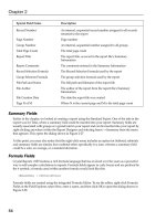
Figure 3.45 Typical current-limiting fuse operation show-
ing brief sag followed by peak arc voltage when the fuse
clears.
Voltage Sags and Interruptions
Downloaded from Digital Engineering Library @ McGraw-Hill (www.digitalengineeringlibrary.com)
Copyright © 2004 The McGraw-Hill Companies. All rights reserved.
Any use is subject to the Terms of Use as given at the website.
Because the third-harmonic current is predominantly zero-sequence, it
affects the ground-fault relaying. There have been incidents where there
have been false trips and lockout due to excessive harmonic currents in
the ground-relaying circuit. At least one of the events we have investi-
gated has been correlated with capacitor switching where it is suspected
that the third-harmonic current was amplified somewhat due to reso-
nance. There may be many more events that we have not heard about,
and it is expected that the problem will only get worse in the future.
The simplest solution is to raise the ground-fault pickup level when
operating procedures will allow. Unfortunately, this makes fault detec-
tion less sensitive, which defeats the purpose of having ground relay-
ing, and some utilities are restrained by standards from raising the
ground trip level. It has been observed that if the third harmonic could
be filtered out, it might be possible to set the ground relaying to be more
sensitive. The third-harmonic current is almost entirely a function of
load and is not a component of fault current. When a fault occurs, the
current seen by the relaying is predominantly sinusoidal. Therefore, it
is not necessary for the relaying to be able to monitor the third har-
monic for fault detection.
The first relays were electromagnetic devices that basically
responded to the effective (rms) value of the current. Thus, for years, it
has been common practice to design electronic relays to duplicate that
response and digital relays have also generally included the significant
lower harmonics. In retrospect, it would have been better if the third
harmonic would have been ignored for ground-fault relays.
There is still a valid reason for monitoring the third harmonic in
phase relaying because phase relaying is used to detect overload as
well as faults. Overload evaluation is generally an rms function.
3.7.14 Utility fault prevention
One sure way to eliminate complaints about utility fault-clearing oper-
ations is to eliminate faults altogether. Of course, there will always be
some faults, but there are many things that can be done to dramatically
reduce the incidence of faults.
18
Overhead line maintenance
Tree trimming. This is one of the more effective methods of reducing
the number of faults on overhead lines. It is a necessity, although the
public may complain about the environmental and aesthetic impact.
Insulator washing. Like tree trimming in wooded regions, insulator
washing is necessary in coastal and dusty regions. Otherwise, there
will be numerous insulator flashovers for even a mild rainstorm with-
out lightning.
Voltage Sags and Interruptions 105
Voltage Sags and Interruptions
Downloaded from Digital Engineering Library @ McGraw-Hill (www.digitalengineeringlibrary.com)
Copyright © 2004 The McGraw-Hill Companies. All rights reserved.
Any use is subject to the Terms of Use as given at the website.
Shield wires. Shield wires for lightning are common for utility trans-
mission systems. They are generally not applied on distribution feed-
ers except where lines have an unusually high incidence of lightning
strikes. Some utilities construct their feeders with the neutral on top,
perhaps even extending the pole, to provide shielding. No shielding is
perfect.
Improving pole grounds. Several utilities have reported doing this to
improve the power quality with respect to faults. However, we are not
certain of all the reasons for doing this. Perhaps, it makes the faults
easier to detect. If shielding is employed, this will reduce the back-
flashover rate. If not, it would not seem that this would provide any
benefit with respect to lightning unless combined with line arrester
applications (see Line Arresters below).
Modified conductor spacing. Employing a different line spacing can
sometimes increase the withstand to flashover or the susceptibility to
getting trees in the line.
Tree wire (insulated/covered conductor). In areas where tree trimming is
not practical, insulated or covered conductor can reduce the likelihood
of tree-induced faults.
UD cables. Fault prevention techniques in underground distribution
(UD) cables are generally related to preserving the insulation against
voltage surges. The insulation degrades significantly as it ages, requir-
ing increasing efforts to keep the cable sound. This generally involves
arrester protection schemes to divert lightning surges coming from the
overhead system, although there are some efforts to restore insulation
levels through injecting fluids into the cable.
Since nearly all cable faults are permanent, the power quality issue
is more one of finding the fault location quickly so that the cable can be
manually sectionalized and repaired. Fault location devices available
for that purpose are addressed in Sec. 3.7.15.
Line arresters. To prevent overhead line faults, one must either raise
the insulation level of the line, prevent lightning from striking the line,
or prevent the voltage from exceeding the insulation level. The third
idea is becoming more popular with improving surge arrester designs.
To accomplish this, surge arresters are placed every two or three poles
along the feeder as well as on distribution transformers. Some utilities
place them on all three phases, while other utilities place them only on
the phase most likely to be struck by lightning. To support some of the
recent ideas about improving power quality, or providing custom power
with superreliable main feeders, it will be necessary to put arresters on
every phase of every pole.
106 Chapter Three
Voltage Sags and Interruptions
Downloaded from Digital Engineering Library @ McGraw-Hill (www.digitalengineeringlibrary.com)
Copyright © 2004 The McGraw-Hill Companies. All rights reserved.
Any use is subject to the Terms of Use as given at the website.
Presently, applying line arresters in addition to the normal arrester
at transformer locations is done only on line sections with a history of
numerous lightning-induced faults. But recently, some utilities have
claimed that applying line arresters is not only more effective than
shielding, but it is more economical.
14
Some sections of urban and suburban feeders will naturally
approach the goal of an arrester every two or three poles because the
density of load requires the installation of a distribution transformer at
least that frequently. Each transformer will normally have a primary
arrester in lightning-prone regions.
3.7.15 Fault locating
Finding faults quickly is an important aspect of reliability and the
quality of power.
Faulted circuit indicators. Finding cable faults is often quite a chal-
lenge. The cables are underground, and it is generally impossible to see
the fault, although occasionally there will be a physical display. To
expedite locating the fault, many utilities use “faulted circuit indica-
tors,” or simply “fault indicators,” to locate the faulted section more
quickly. These are devices that flip a target indicator when the current
exceeds a particular level. The idea is to put one at each pad-mount
transformer; the last one showing a target will be located just before
the faulted section.
There are two main schools of thought on the selection of ratings of
faulted circuit indicators. The more traditional school says to choose a
rating that is 2 to 3 times the maximum expected load on the cable.
This results in a fairly sensitive fault detection capability.
The opposing school says that this is too sensitive and is the reason
that many fault indicators give a false indication. A false indication
delays the location of the fault and contributes to degraded reliability
and power quality. The reason given for the false indication is that the
energy stored in the cable generates sufficient current to trip the indi-
cator when the fault occurs. Thus, a few indicators downline from the
fault may also show the fault. The solution to this problem is to apply
the indicator with a rating based on the maximum fault current avail-
able rather than on the maximum load current. This is based on the
assumption that most cable faults quickly develop into bolted faults.
Therefore, the rating is selected allowing for a margin of 10 to 20 per-
cent.
Another issue impacting the use of fault indicators is DG. With mul-
tiple sources on the feeder capable of supplying fault current, there will
be an increase in false indications. In some cases, it is likely that all the
fault indicators between the generator locations and the fault will be
Voltage Sags and Interruptions 107
Voltage Sags and Interruptions
Downloaded from Digital Engineering Library @ McGraw-Hill (www.digitalengineeringlibrary.com)
Copyright © 2004 The McGraw-Hill Companies. All rights reserved.
Any use is subject to the Terms of Use as given at the website.
tripped. It will be a challenge to find new technologies that work ade-
quately in this environment. This is just one example of the subtle
impacts on utility practice resulting from sufficient DG penetration to
significantly alter fault currents.
Fault indicators must be reset before the next fault event. Some
must be reset manually, while others have one of a number of tech-
niques for detecting, or assuming, the restoration of power and reset-
ting automatically. Some of the techniques include test point reset,
low-voltage reset, current reset, electrostatic reset, and time reset.
Locating cable faults without fault indicators. Without fault indicators,
the utility must rely on more manual techniques for finding the loca-
tion of a fault. There are a large number of different types of fault-locat-
ing techniques and a detailed description of each is beyond the scope of
this report. Some of the general classes of methods follow.
Thumping. This is a common practice with numerous minor varia-
tions. The basic technique is to place a dc voltage on the cable that is
sufficient to cause the fault to be reestablished and then try to detect
by sight, sound, or feel the physical display from the fault. One common
way to do this is with a capacitor bank that can store enough energy to
generate a sufficiently loud noise. Those standing on the ground on top
of the fault can feel and hear the “thump” from the discharge. Some
combine this with cable radar techniques to confirm estimates of dis-
tance. Many are concerned with the potential damage to the sound por-
tion of the cable due to thumping techniques.
Cable radar and other pulse methods. These techniques make use of trav-
eling-wave theory to produce estimates of the distance to the fault. The
wave velocity on the cable is known. Therefore, if an impulse is injected
into the cable, the time for the reflection to return will be proportional
to the length of the cable to the fault. An open circuit will reflect the
voltage wave back positively while a short circuit will reflect it back
negatively. The impulse current will do the opposite. If the routing of
the cable is known, the fault location can be found simply by measur-
ing along the route. It can be confirmed and fine-tuned by thumping
the cable. On some systems, there are several taps off the cable. The
distance to the fault is only part of the story; one has to determine
which branch it is on. This can be a very difficult problem that is still a
major obstacle to rapidly locating a cable fault.
Tone. A tone system injects a high-frequency signal on the cable, and
the route of the cable can be followed by a special receiver. This tech-
nique is sometimes used to trace the cable route while it is energized,
but is also useful for fault location because the tone will disappear
beyond the fault location.
108 Chapter Three
Voltage Sags and Interruptions
Downloaded from Digital Engineering Library @ McGraw-Hill (www.digitalengineeringlibrary.com)
Copyright © 2004 The McGraw-Hill Companies. All rights reserved.
Any use is subject to the Terms of Use as given at the website.
Fault chasing with a fuse. The cable is manually sectionalized, and then
each section is reenergized until a fuse blows. The faulted section is
determined by the process of elimination or by observing the physical
display from the fault. Because of the element of danger and the possi-
bility of damaging cable components, some utilities strongly discourage
this practice. Others require the use of small current-limiting fuses,
which minimize the amount of energy permitted into the fault. This
can be an expensive and time-consuming procedure that some consider
to be the least effective of fault-locating methods and one that should
be used only as a last resort. This also subjects end users to nuisance
voltage sags.
3.8 References
1. J. Lamoree, J. C. Smith, P. Vinett, T. Duffy, M. Klein, “The Impact of Voltage Sags on
Industrial Plant Loads,” First International Conference on Power Quality, PQA ’91,
Paris, France.
2. P. Vinett, R. Temple, J. Lamoree, C. De Winkel, E. Kostecki, “Application of a
Superconducting Magnetic Energy Storage Device to Improve Facility Power
Quality,” Proceedings of the Second International Conference on Power Quality: End-
use Applications and Perspectives, PQA ’92, Atlanta, GA, September 1992.
3. G. Beam, E. G Dolack, C. J. Melhorn, V. Misiewicz, M. Samotyj, “Power Quality Case
Studies, Voltage Sags: The Impact on the Utility and Industrial Customers,” Third
International Conference on Power Quality, PQA ’93, San Diego, CA, November 1993.
4. J. Lamoree, D. Mueller, P. Vinett, W. Jones, “Voltage Sag Analysis Case Studies,”
1993 IEEE I&CPS Conference, St. Petersburg, FL.
5. M. F. McGranaghan, D. R. Mueller, M. J. Samotyj, “Voltage Sags in Industrial
Systems,” IEEE Transactions on Industry Applications, vol. 29, no. 2, March/April
1993.
6. Le Tang, J. Lamoree, M. McGranaghan, H. Mehta, “Distribution System Voltage
Sags: Interaction with Motor and Drive Loads,” IEEE Transmission and Distribution
Conference, Chicago, IL, April 10–15, 1994, pp. 1–6.
7. EPRI RP 3098-1, An Assessment of Distribution Power Quality, Electric Power
Research Institute, Palo Alto, CA.
8. IEEE Standard Guide for Electric Power Distribution Reliability Indices, IEEE
Standard 1366-2001.
9. James J. Burke, Power Distribution Engineering: Fundamentals and Applications,
Marcel Dekker, Inc., 1994.
10. C. M. Warren, “The Effect of Reducing Momentary Outages on Distribution
Reliability Indices,” IEEE Transactions on Power Delivery, July 1993, pp. 1610–1617.
11. R. C. Dugan, L. A. Ray, D. D. Sabin, et al., “Impact of Fast Tripping of Utility
Breakers on Industrial Load Interruptions,” Conference Record of the 1994
IEEE/IAS Annual Meeting, Vol. III, Denver, October 1994, pp. 2326–2333.
12. T. Roughan, P. Freeman, “Power Quality and the Electric Utility, Reducing the
Impact of Feeder Faults on Customers,” Proceedings of the Second International
Conference on Power Quality: End-use Applications and Perspectives (PQA ’92),
EPRI, Atlanta, GA, September 28–30, 1992.
13. J. Lamoree, Le Tang, C. De Winkel, P. Vinett, “Description of a Micro-SMES System
for Protection of Critical Customer Facilities,” IEEE Transactions on Power Delivery,
April 1994, pp. 984–991.
14. Randall A. Stansberry, “Protecting Distribution Circuits: Overhead Shield Wire
Versus Lightning Surge Arresters,” Transmission & Distribution, April 1991, pp.
56ff.
Voltage Sags and Interruptions 109
Voltage Sags and Interruptions
Downloaded from Digital Engineering Library @ McGraw-Hill (www.digitalengineeringlibrary.com)
Copyright © 2004 The McGraw-Hill Companies. All rights reserved.
Any use is subject to the Terms of Use as given at the website.
15. S. Santoso, R. Zavadil, D. Folts, M.F McGranaghan, T. E Grebe, “Modeling and
Analysis of a 1.7 MVA SMES-based Sag Protector,” Proceedings of the 4th
International Conference on Power System Transients Conference, Rio de Janeiro,
Brazil, June 24–28, 2001, pp. 115–119.
16. Math H. J. Bollen, Understanding Power Quality Problems, Voltage Sags and
Interruptions, IEEE Press Series on Power Engineering, The Institute of Electrical
and Electronics Engineers, Inc., New York, 2000.
17. SEMI Standard F-47, Semiconductor Equipment and Materials International, 1999.
18. IEEE Standard 1346-1998, Recommended Practice for Evaluating Electric Power
System Compatibility with Electronic Process Equipment.
110 Chapter Three
Voltage Sags and Interruptions
Downloaded from Digital Engineering Library @ McGraw-Hill (www.digitalengineeringlibrary.com)
Copyright © 2004 The McGraw-Hill Companies. All rights reserved.
Any use is subject to the Terms of Use as given at the website.
111
Transient Overvoltages
4.1 Sources of Transient Overvoltages
There are two main sources of transient overvoltages on utility sys-
tems: capacitor switching and lightning. These are also sources of tran-
sient overvoltages as well as a myriad of other switching phenomena
within end-user facilities. Some power electronic devices generate sig-
nificant transients when they switch. As described in Chap. 2, tran-
sient overvoltages can be generated at high frequency (load switching
and lightning), medium frequency (capacitor energizing), or low fre-
quency.
4.1.1 Capacitor switching
Capacitor switching is one of the most common switching events on
utility systems. Capacitors are used to provide reactive power (in units
of vars) to correct the power factor, which reduces losses and supports
the voltage on the system. They are a very economical and generally
trouble-free means of accomplishing these goals. Alternative methods
such as the use of rotating machines and electronic var compensators
are much more costly or have high maintenance costs. Thus, the use of
capacitors on power systems is quite common and will continue to be.
One drawback to the use of capacitors is that they yield oscillatory
transients when switched. Some capacitors are energized all the time
(a fixed bank), while others are switched according to load levels.
Various control means, including time, temperature, voltage, current,
and reactive power, are used to determine when the capacitors are
switched. It is common for controls to combine two or more of these
functions, such as temperature with voltage override.
Chapter
4
Source: Electrical Power Systems Quality
Downloaded from Digital Engineering Library @ McGraw-Hill (www.digitalengineeringlibrary.com)
Copyright © 2004 The McGraw-Hill Companies. All rights reserved.
Any use is subject to the Terms of Use as given at the website.
One of the common symptoms of power quality problems related to
utility capacitor switching overvoltages is that the problems appear at
nearly the same time each day. On distribution feeders with industrial
loads, capacitors are frequently switched by time clock in anticipation
of an increase in load with the beginning of the working day. Common
problems are adjustable-speed-drive trips and malfunctions of other
electronically controlled load equipment that occur without a notice-
able blinking of the lights or impact on other, more conventional loads.
Figure 4.1 shows the one-line diagram of a typical utility feeder
capacitor-switching situation. When the switch is closed, a transient
similar to the one in Fig. 4.2 may be observed upline from the capaci-
tor at the monitor location. In this particular case, the capacitor switch
contacts close at a point near the system voltage peak. This is a com-
mon occurrence for many types of switches because the insulation
across the switch contacts tends to break down when the voltage across
the switch is at a maximum value. The voltage across the capacitor at
this instant is zero. Since the capacitor voltage cannot change instan-
taneously, the system voltage at the capacitor location is briefly pulled
down to zero and rises as the capacitor begins to charge toward the sys-
tem voltage. Because the power system source is inductive, the capaci-
tor voltage overshoots and rings at the natural frequency of the system.
At the monitoring location shown, the initial change in voltage will not
go completely to zero because of the impedance between the observa-
tion point and the switched capacitor. However, the initial drop and
subsequent ringing transient that is indicative of a capacitor-switching
event will be observable to some degree.
The overshoot will generate a transient between 1.0 and 2.0 pu
depending on system damping. In this case the transient observed at
the monitoring location is about 1.34 pu. Utility capacitor-switching
transients are commonly in the 1.3- to 1.4-pu range but have also been
observed near the theoretical maximum.
The transient shown in the oscillogram propagates into the local
power system and will generally pass through distribution transform-
ers into customer load facilities by nearly the amount related to the
turns ratio of the transformer. If there are capacitors on the secondary
system, the voltage may actually be magnified on the load side of the
transformer if the natural frequencies of the systems are properly
aligned (see Sec. 4.1.2). While such brief transients up to 2.0 pu are not
generally damaging to the system insulation, they can often cause
misoperation of electronic power conversion devices. Controllers may
interpret the high voltage as a sign that there is an impending danger-
ous situation and subsequently disconnect the load to be safe. The tran-
sient may also interfere with the gating of thyristors.
112 Chapter Four
Transient Overvoltages
Downloaded from Digital Engineering Library @ McGraw-Hill (www.digitalengineeringlibrary.com)
Copyright © 2004 The McGraw-Hill Companies. All rights reserved.
Any use is subject to the Terms of Use as given at the website.
Switching of grounded-wye transformer banks may also result in
unusual transient voltages in the local grounding system due to the
current surge that accompanies the energization. Figure 4.3 shows the
phase current observed for the capacitor-switching incident described
in the preceding text. The transient current flowing in the feeder peaks
at nearly 4 times the load current.
Transient Overvoltages 113
y
FEEDER IMPEDANCE
MONITOR
LOCATION
SUBSTATION
SWITCHED
CAPACITOR
Figure 4.1 One-line diagram of a capacitor-switching operation corre-
sponding to the waveform in Fig. 4.2.
Phase A Voltage
Wave Fault
0 10 203040506070
–150
–100
–50
0
50
100
150
Time (ms)
% Volts
Figure 4.2 Typical utility capacitor-switching transient reaching
134 percent voltage, observed upline from the capacitor.
Transient Overvoltages
Downloaded from Digital Engineering Library @ McGraw-Hill (www.digitalengineeringlibrary.com)
Copyright © 2004 The McGraw-Hill Companies. All rights reserved.
Any use is subject to the Terms of Use as given at the website.
4.1.2 Magnification of capacitor-switching
transients
A potential side effect of adding power factor correction capacitors at
the customer location is that they may increase the impact of utility
capacitor-switching transients on end-use equipment. As shown in Sec.
4.1.1, there is always a brief voltage transient of at least 1.3 to 1.4 pu
when capacitor banks are switched. The transient is generally no
higher than 2.0 pu on the primary distribution system, although
ungrounded capacitor banks may yield somewhat higher values. Load-
side capacitors can magnify this transient overvoltage at the end-user
bus for certain low-voltage capacitor and step-down transformer sizes.
The circuit of concern for this phenomenon is illustrated in Fig. 4.4.
Transient overvoltages on the end-user side may reach as high as 3.0
to 4.0 pu on the low-voltage bus under these conditions, with poten-
tially damaging consequences for all types of customer equipment.
Magnification of utility capacitor-switching transients at the end-
user location occurs over a wide range of transformer and capacitor
sizes. Resizing the customer’s power factor correction capacitors or
step-down transformer is therefore usually not a practical solution.
One solution is to control the transient overvoltage at the utility capac-
114 Chapter Four
Phase A Current
Wave Fault
010203040506070
–400
–300
–200
–100
0
100
200
300
400
Time (ms)
Amps
Figure 4.3 Feeder current associated with capacitor-switching event.
Transient Overvoltages
Downloaded from Digital Engineering Library @ McGraw-Hill (www.digitalengineeringlibrary.com)
Copyright © 2004 The McGraw-Hill Companies. All rights reserved.
Any use is subject to the Terms of Use as given at the website.
itor. This is sometimes possible using synchronous closing breakers or
switches with preinsertion resistors. These solutions are discussed in
more detail in Sec. 4.4.2.
At the customer location, high-energy surge arresters can be applied
to limit the transient voltage magnitude at the customer bus. Energy
levels associated with the magnified transient will typically be about 1
kJ. Figure 4.5 shows the expected arrester energy for a range of low-
voltage capacitor sizes. Newer high-energy MOV arresters for low-volt-
age applications can withstand 2 to 4 kJ.
It is important to note that the arresters can only limit the transient
to the arrester protective level. This will typically be approximately
Transient Overvoltages 115
(a) Voltage magnification at customer capacitor due to
energizing capacitor on utility system
(b) Equivalent circuit
f
1
L
1
C
1
f
2
L
2
C
2
1
2
1
2
=
=
π
π
Switching frequency
Natural frequency of
customer resonant circuit
Voltage magnification f
1
f
2
⇔≈
V
V
C
2
L
1
L
2
C
2
C
1
Load
Feeder
Source
Substation
Service
Transformer
C
1
C
2
L
2
L
1
C
1
Figure 4.4 Voltage magnification of capacitor bank switching.
Transient Overvoltages
Downloaded from Digital Engineering Library @ McGraw-Hill (www.digitalengineeringlibrary.com)
Copyright © 2004 The McGraw-Hill Companies. All rights reserved.
Any use is subject to the Terms of Use as given at the website.
1.8 times the normal peak voltage (1.8 pu). This may not be sufficient
to protect sensitive electronic equipment that might only have a with-
stand capability of 1.75 pu [1200-V peak inverse voltage (PIV) rating of
many silicon-controlled rectifiers (SCRs) used in the industrial envi-
ronment]. It may not be possible to improve the protective characteris-
tics of the arresters substantially because these characteristics are
limited by the physics of the metal-oxide materials. Therefore, for
proper coordination, it is important to carefully evaluate the withstand
capabilities of sensitive equipment used in applications where these
transients can occur.
Another means of limiting the voltage magnification transient is to
convert the end-user power factor correction banks to harmonic filters.
An inductance in series with the power factor correction bank will
decrease the transient voltage at the customer bus to acceptable levels.
This solution has multiple benefits including providing correction for
the displacement power factor, controlling harmonic distortion levels
within the facility, and limiting the concern for magnified capacitor-
switching transients.
In many cases, there are only a small number of load devices, such
as adjustable-speed motor drives, that are adversely affected by the
transient. It is frequently more economical to place line reactors in
series with the drives to block the high-frequency magnification tran-
sient. A 3 percent reactor is generally effective. While offering only a
small impedance to power frequency current, it offers a considerably
larger impedance to the transient. Many types of drives have this pro-
tection inherently, either through an isolation transformer or a dc bus
reactance.
116 Chapter Four
0
500
1000
1500
2000
2500
0 100 200 300 400 500 600
Energy (J)
Low-Voltage Capacitor Size (kVAR)
6.0 MVAR
4.5 MVAR
3.0 MVAR
2.4 MVAR
1.8 MVAR
Switched Cap Size
Step-Down Transformer = 1500 kVA
1.2 MVAR
Figure 4.5 Arrester energy duty caused by magnified transient.
Transient Overvoltages
Downloaded from Digital Engineering Library @ McGraw-Hill (www.digitalengineeringlibrary.com)
Copyright © 2004 The McGraw-Hill Companies. All rights reserved.
Any use is subject to the Terms of Use as given at the website.
4.1.3 Lightning
Lightning is a potent source of impulsive transients. We will not devote
space to the physical phenomena here because that topic is well docu-
mented in other reference books.
1–3
We will concentrate on how light-
ning causes transient overvoltages to appear on power systems.
Figure 4.6 illustrates some of the places where lightning can strike
that results in lightning currents being conducted from the power sys-
tem into loads.
The most obvious conduction path occurs during a direct strike to a
phase wire, either on the primary or the secondary side of the trans-
former. This can generate very high overvoltages, but some analysts
question whether this is the most common way that lightning surges
enter load facilities and cause damage. Very similar transient over-
voltages can be generated by lightning currents flowing along ground
conductor paths. Note that there can be numerous paths for lightning
currents to enter the grounding system. Common ones, indicated by
the dotted lines in Fig. 4.6, include the primary ground, the secondary
ground, and the structure of the load facilities. Note also that strikes to
the primary phase are conducted to the ground circuits through the
arresters on the service transformer. Thus, many more lightning
impulses may be observed at loads than one might think.
Keep in mind that grounds are never perfect conductors, especially
for impulses. While most of the surge current may eventually be dissi-
pated into the ground connection closest to the strike, there will be sub-
stantial surge currents flowing in other connected ground conductors
in the first few microseconds of the strike.
Transient Overvoltages 117
Figure 4.6 Lightning strike locations where lightning impulses will be con-
ducted into load facilities.
PRIMARY
PHASE
SECONDARY
PHASE
PRIMARY
GROUND
GROUNDED
STRUCTURE
SECONDARY GROUND
ARRESTER
Transient Overvoltages
Downloaded from Digital Engineering Library @ McGraw-Hill (www.digitalengineeringlibrary.com)
Copyright © 2004 The McGraw-Hill Companies. All rights reserved.
Any use is subject to the Terms of Use as given at the website.
A direct strike to a phase conductor generally causes line flashover
near the strike point. Not only does this generate an impulsive tran-
sient, but it causes a fault with the accompanying voltage sags and
interruptions. The lightning surge can be conducted a considerable dis-
tance along utility lines and cause multiple flashovers at pole and
tower structures as it passes. The interception of the impulse from the
phase wire is fairly straightforward if properly installed surge
arresters are used. If the line flashes over at the location of the strike,
the tail of the impulse is generally truncated. Depending on the effec-
tiveness of the grounds along the surge current path, some of the cur-
rent may find its way into load apparatus. Arresters near the strike
may not survive because of the severe duty (most lightning strokes are
actually many strokes in rapid-fire sequence).
Lightning does not have to actually strike a conductor to inject
impulses into the power system. Lightning may simply strike near the
line and induce an impulse by the collapse of the electric field.
Lightning may also simply strike the ground near a facility causing the
local ground reference to rise considerably. This may force currents
along grounded conductors into a remote ground, possibly passing near
sensitive load apparatus.
Many investigators in this field postulate that lightning surges enter
loads from the utility system through the interwinding capacitance of
the service transformer as shown in Fig. 4.7. The concept is that the
lightning impulse is so fast that the inductance of the transformer
windings blocks the first part of the wave from passing through by the
turns ratio. However, the interwinding capacitance may offer a ready
path for the high-frequency surge. This can permit the existence of a
voltage on the secondary terminals that is much higher than what the
turns ratio of the windings would suggest.
The degree to which capacitive coupling occurs is greatly dependent
on the design of the transformer. Not all transformers have a straight-
forward high-to-low capacitance because of the way the windings are
constructed. The winding-to-ground capacitance may be greater than
the winding-to-winding capacitance, and more of the impulse may
actually be coupled to ground than to the secondary winding. In any
case, the resulting transient is a very short single impulse, or train of
impulses, because the interwinding capacitance charges quickly.
Arresters on the secondary winding should have no difficulty dissipat-
ing the energy in such a surge, but the rates of rise can be high. Thus,
lead length becomes very important to the success of an arrester in
keeping this impulse out of load equipment.
Many times, a longer impulse, which is sometimes oscillatory, is
observed on the secondary when there is a strike to a utility’s primary
118 Chapter Four
Transient Overvoltages
Downloaded from Digital Engineering Library @ McGraw-Hill (www.digitalengineeringlibrary.com)
Copyright © 2004 The McGraw-Hill Companies. All rights reserved.
Any use is subject to the Terms of Use as given at the website.
distribution system. This is likely due not to capacitive coupling
through the service transformer but to conduction around the trans-
former through the grounding systems as shown in Fig. 4.8. This is a
particular problem if the load system offers a better ground and much
of the surge current flows through conductors in the load facility on its
way to ground.
The chief power quality problems with lightning stroke currents
entering the ground system are
1. They raise the potential of the local ground above other grounds in
the vicinity by several kilovolts. Sensitive electronic equipment that
is connected between two ground references, such as a computer
connected to the telephone system through a modem, can fail when
subjected to the lightning surge voltages.
2. They induce high voltages in phase conductors as they pass through
cables on the way to a better ground.
The problems are related to the so-called low-side surge problem that
is described in Sec. 4.5.3.
Ideas about lightning are changing with recent research.
10
Lightning
causes more flashovers of utility lines than previously thought.
Evidence is also mounting that lightning stroke current wavefronts are
faster than previously thought and that multiple strikes appear to be
the norm rather than the exception. Durations of some strokes may
also be longer than reported by earlier researchers. These findings may
help explain failures of lightning arresters that were thought to have
adequate capacity to handle large lightning strokes.
Transient Overvoltages 119
Figure 4.7 Coupling of impulses through the interwinding
capacitance of transformers.
Transient Overvoltages
Downloaded from Digital Engineering Library @ McGraw-Hill (www.digitalengineeringlibrary.com)
Copyright © 2004 The McGraw-Hill Companies. All rights reserved.
Any use is subject to the Terms of Use as given at the website.
4.1.4 Ferroresonance
The term ferroresonance refers to a special kind of resonance that
involves capacitance and iron-core inductance. The most common con-
dition in which it causes disturbances is when the magnetizing imped-
ance of a transformer is placed in series with a system capacitor. This
happens when there is an open-phase conductor. Under controlled con-
ditions, ferroresonance can be exploited for useful purpose such as in a
constant-voltage transformer (see Chap. 3).
Ferroresonance is different than resonance in linear system ele-
ments. In linear systems, resonance results in high sinusoidal voltages
and currents of the resonant frequency. Linear-system resonance is the
phenomenon behind the magnification of harmonics in power systems
(see Chaps. 5 and 6). Ferroresonance can also result in high voltages
and currents, but the resulting waveforms are usually irregular and
chaotic in shape. The concept of ferroresonance can be explained in
terms of linear-system resonance as follows.
Consider a simple series RLC circuit as shown in Fig. 4.9. Neglecting
the resistance R for the moment, the current flowing in the circuit can
be expressed as follows:
I ϭ
where E ϭ driving voltage
X
L
ϭ reactance of L
X
C
ϭ reactance of C
When X
L
ϭ |X
C
|, a series-resonant circuit is formed, and the equation
yields an infinitely large current that in reality would be limited by R.
An alternate solution to the series RLC circuit can be obtained by
writing two equations defining the voltage across the inductor, i.e.,
E
ᎏᎏ
j (X
L
Ϫ |X
C
|)
120 Chapter Four
TRANSFORMER
GROUND
OTHER GROUND
PRIMARY
ARRESTER
Figure 4.8 Lightning impulse bypassing the service
transformer through ground connections.
Transient Overvoltages
Downloaded from Digital Engineering Library @ McGraw-Hill (www.digitalengineeringlibrary.com)
Copyright © 2004 The McGraw-Hill Companies. All rights reserved.
Any use is subject to the Terms of Use as given at the website.
v ϭ jX
L
I
v ϭ E ϩ j|X
C
|I
where v is a voltage variable. Figure 4.10 shows the graphical solution
of these two equations for two different reactances, X
L
and X
L
′. X
L
′ rep-
resents the series-resonant condition. The intersection point between
the capacitive and inductive lines gives the voltage across inductor E
L
.
The voltage across capacitor E
C
is determined as shown in Fig. 4.10. At
resonance, the two lines will intersect at infinitely large voltage and
current since the |X
C
| line is parallel to the X
L
′ line.
Now, let us assume that the inductive element in the circuit has a
nonlinear reactance characteristic like that found in transformer mag-
netizing reactance. Figure 4.11 illustrates the graphical solution of the
equations following the methodology just presented for linear circuits.
While the analogy cannot be made perfectly, the diagram is useful to
help understand ferroresonance phenomena.
It is obvious that there may be as many as three intersections
between the capacitive reactance line and the inductive reactance
curve. Intersection 2 is an unstable solution, and this operating point
gives rise to some of the chaotic behavior of ferroresonance.
Intersections 1 and 3 are stable and will exist in the steady state.
Intersection 3 results in high voltages and high currents.
Figures 4.12 and 4.13 show examples of ferroresonant voltages that
can result from this simple series circuit. The same inductive charac-
teristic was assumed for each case. The capacitance was varied to
achieve a different operating point after an initial transient that
pushes the system into resonance. The unstable case yields voltages in
excess of 4.0 pu, while the stable case settles in at voltages slightly over
2.0 pu. Either condition can impose excessive duty on power system ele-
ments and load equipment.
For a small capacitance, the |X
C
| line is very steep, resulting in an
intersection point on the third quadrant only. This can yield a range of
voltages from less than 1.0 pu to voltages like those shown in Fig. 4.13.
Transient Overvoltages 121
X
L
X
C
R
E
I
Figure 4.9 Simple series RLC circuit.
Transient Overvoltages
Downloaded from Digital Engineering Library @ McGraw-Hill (www.digitalengineeringlibrary.com)
Copyright © 2004 The McGraw-Hill Companies. All rights reserved.
Any use is subject to the Terms of Use as given at the website.
122 Chapter Four
X
L
X'
L
E
L
E
X
C
v
jI
E
E
C
E
L
Figure 4.10 Graphical solution to the linear LC circuit.
X
C
X
L
v
jI
increasing
capacitance
E
L
E
2
1
3
jIjI
E
L
E
C
E
Figure 4.11 Graphical solution to the nonlinear LC circuit.
Transient Overvoltages
Downloaded from Digital Engineering Library @ McGraw-Hill (www.digitalengineeringlibrary.com)
Copyright © 2004 The McGraw-Hill Companies. All rights reserved.
Any use is subject to the Terms of Use as given at the website.
When C is very large, the capacitive reactance line will intersect only
at points 1 and 3. One operating state is of low voltage and lagging cur-
rent (intersection 1), and the other is of high voltage and leading cur-
rent (intersection 3). The operating points during ferroresonance can
oscillate between intersection points 1 and 3 depending on the applied
voltage. Often, the resistance in the circuit prevents operation at point
3 and no high voltages will occur.
In practice, ferroresonance most commonly occurs when unloaded
transformers become isolated on underground cables of a certain range
Transient Overvoltages 123
–5
–4
–3
–2
–1
0
1
2
3
4
5
V, per unit
Figure 4.12 Example of unstable, chaotic ferroresonance voltages.
–4
–3
–2
–1
0
1
2
3
4
5
V, per unit
Figure 4.13 Example of ferroresonance voltages settling into a stable operating point
(intersection 3) after an initial transient.
Transient Overvoltages
Downloaded from Digital Engineering Library @ McGraw-Hill (www.digitalengineeringlibrary.com)
Copyright © 2004 The McGraw-Hill Companies. All rights reserved.
Any use is subject to the Terms of Use as given at the website.
of lengths. The capacitance of overhead distribution lines is generally
insufficient to yield the appropriate conditions.
The minimum length of cable required to cause ferroresonance
varies with the system voltage level. The capacitance of cables is
nearly the same for all distribution voltage levels, varying from 40 to
100 nF per 1000 feet (ft), depending on conductor size. However, the
magnetizing reactance of a 35-kV-class distribution transformer is
several times higher (the curve is steeper) than a comparably sized
15-kV-class transformer. Therefore, damaging ferroresonance has
been more common at the higher voltages. For delta-connected trans-
formers, ferroresonance can occur for less than 100 ft of cable. For
this reason, many utilities avoid this connection on cable-fed trans-
formers. The grounded wye-wye transformer has become the most
commonly used connection in underground systems in North
American. It is more resistant, but not immune, to ferroresonance
because most units use a three-legged or five-legged core design that
couples the phases magnetically. It may require a minimum of several
hundred feet of cable to provide enough capacitance to create a fer-
roresonant condition for this connection.
The most common events leading to ferroresonance are
■
Manual switching of an unloaded, cable-fed, three-phase trans-
former where only one phase is closed (Fig. 4.14a). Ferroresonance
may be noted when the first phase is closed upon energization or
before the last phase is opened on deenergization.
■
Manual switching of an unloaded, cable-fed, three-phase trans-
former where one of the phases is open (Fig. 4.14b). Again, this may
happen during energization or deenergization.
■
One or two riser-pole fuses may blow leaving a transformer with one
or two phases open. Single-phase reclosers may also cause this con-
dition. Today, many modern commercial loads have controls that
transfer the load to backup systems when they sense this condition.
Unfortunately, this leaves the transformer without any load to damp
out the resonance.
It should be noted that these events do not always yield noticeable fer-
roresonance. Some utility personnel claim to have worked with under-
ground cable systems for decades without seeing ferroresonance. System
conditions that help increase the likelihood of ferroresonance include
■
Higher distribution voltage levels, most notably 25- and 35-kV-class
systems
■
Switching of lightly loaded and unloaded transformers
■
Ungrounded transformer primary connections
124 Chapter Four
Transient Overvoltages
Downloaded from Digital Engineering Library @ McGraw-Hill (www.digitalengineeringlibrary.com)
Copyright © 2004 The McGraw-Hill Companies. All rights reserved.
Any use is subject to the Terms of Use as given at the website.
■
Very lengthy underground cable circuits
■
Cable damage and manual switching during construction of under-
ground cable systems
■
Weak systems, i.e., low short-circuit currents
■
Low-loss transformers
■
Three-phase systems with single-phase switching devices
Transient Overvoltages 125
A
B
C
(a)
A
B
C
(b)
Figure 4.14 Common system conditions where ferroresonance
may occur: (a) one phase closed, (b) one phase open.
Transient Overvoltages
Downloaded from Digital Engineering Library @ McGraw-Hill (www.digitalengineeringlibrary.com)
Copyright © 2004 The McGraw-Hill Companies. All rights reserved.
Any use is subject to the Terms of Use as given at the website.
While it is easier to cause ferroresonance at the higher voltage lev-
els, its occurrence is possible at all distribution voltage levels. The pro-
portion of losses, magnetizing reactance, and capacitance at lower
levels may limit the effects of ferroresonance, but it can still occur.
There are several modes of ferroresonance with varying physical and
electrical manifestations. Some have very high voltages and currents,
while others have voltages close to normal. There may or may not be
failures or other evidence of ferroresonance in the electrical compo-
nents. Therefore, it may be difficult to tell if ferroresonance has
occurred in many cases, unless there are witnesses or power quality
measurement instruments.
Common indicators of ferroresonance are as follows.
Audible noise. During ferroresonance, there may be an audible noise,
often likened to that of a large bucket of bolts being shook, whining, a
buzzer, or an anvil chorus pounding on the transformer enclosure from
within. The noise is caused by the magnetostriction of the steel core
being driven into saturation. While difficult to describe in words, this
noise is distinctively different and louder than the normal hum of a
transformer. Most electrical system operating personnel are able to rec-
ognize it immediately upon first hearing it.
Overheating. Transformer overheating often, although not always,
accompanies ferroresonance. This is especially true when the iron core
is driven deep into saturation. Since the core is saturated repeatedly,
the magnetic flux will find its way into parts of the transformer where
the flux is not expected such as the tank wall and other metallic parts.
The stray flux heating is often evidenced from the charring or bubbling
of the paint on the top of the tank. This is not necessarily an indication
that the unit is damaged, but damage can occur in this situation if fer-
roresonance has persisted sufficiently long to cause overheating of
some of the larger internal connections. This may in turn damage solid
insulation structures beyond repair. It should be noted that some
transformers exhibiting signs of ferroresonance such as loud, chaotic
noises do not show signs of appreciable heating. The design of the
transformer and the ferroresonance mode determine how the trans-
former will respond.
High overvoltages and surge arrester failure. When overvoltages accom-
pany ferroresonance, there could be electrical damage to both the pri-
mary and secondary circuits. Surge arresters are common casualties of
the event. They are designed to intercept brief overvoltages and clamp
them to an acceptable level. While they may be able to withstand
126 Chapter Four
Transient Overvoltages
Downloaded from Digital Engineering Library @ McGraw-Hill (www.digitalengineeringlibrary.com)
Copyright © 2004 The McGraw-Hill Companies. All rights reserved.
Any use is subject to the Terms of Use as given at the website.
several overvoltage events, there is a definite limit to their energy
absorption capabilities. Low-voltage arresters in end-user facilities are
more susceptible than utility arresters, and their failure is sometimes
the only indication that ferroresonance has occurred.
Flicker. During ferroresonance the voltage magnitude may fluctuate
wildly. End users at the secondary circuit may actually see their light
bulbs flicker. Some electronic appliances may be very susceptible to
such voltage excursions. Prolonged exposure can shorten the expected
life of the equipment or may cause immediate failure. In facilities that
transfer over to the UPS system in the event of utility-side distur-
bances, repeated and persistent sounding of the alarms on the UPS
may occur as the voltage fluctuates.
4.1.5 Other switching transients
Line energization transients occur, as the term implies, when a switch
is closed connecting a line to the power system. They generally involve
higher-frequency content than capacitor energizing transients. The
transients are a result of a combination of traveling-wave effects and
the interaction of the line capacitance and the system equivalent
source inductance. Traveling waves are caused by the distributed
nature of the capacitance and inductance of the transmission or dis-
tribution line. Line energizing transients typically result in rather
benign overvoltages at distribution voltage levels and generally do not
cause any concern. It is very unusual to implement any kind of switch-
ing control for line energizing except for transmission lines operating
at 345 kV and above. Line energizing transients usually die out in
about 0.5 cycle.
The energization transients on distribution feeder circuits consist of
a combination of line energizing transients, transformer energizing
inrush characteristics, and load inrush characteristics. Figure 4.15
shows a typical case in which the monitor was located on the line side
of the switch. The initial transient frequency is above 1.0 kHz and
appears as a small amount of “hash” on the front of the waveform.
Following the energization, the voltage displays noticeable distortion
caused by the transformer inrush current that contains a number of
low-order harmonic components, including the second and fourth har-
monics. This is evidenced by the lack of symmetry in the voltage wave-
form in the few cycles recorded. This will eventually die out in nearly
all cases. The first peak of the current waveform displays the basic
characteristic of magnetizing inrush, which is subsequently swamped
by the load inrush current.
Transient Overvoltages 127
Transient Overvoltages
Downloaded from Digital Engineering Library @ McGraw-Hill (www.digitalengineeringlibrary.com)
Copyright © 2004 The McGraw-Hill Companies. All rights reserved.
Any use is subject to the Terms of Use as given at the website.
Line energizing transients do not usually pose a problem for end-
user equipment. Equipment can be protected from the high-frequency
components with inductive chokes and surge protective devices if
necessary. The example shown in Fig. 4.15 is relatively benign and
should pose few problems. Cases with less load may exhibit much more
oscillatory behavior.
Another source for overvoltages that is somewhat related to switch-
ing is the common single-line-to-ground fault. On a system with high,
zero-sequence impedance, the sound phase will experience a voltage
rise during the fault. The typical voltage rise on effectively grounded
four-wire, multigrounded neutral systems is generally no more than 15
to 20 percent. On systems with neutral reactors that limit the fault cur-
rent, for example, the voltage rise may reach 40 to 50 percent. This
overvoltage is temporary and will disappear after the fault is cleared.
These overvoltages are not often a problem, but there are potential
problems if the fault clearing is slow:
■
Some secondary arresters installed by end users attempt to clamp
the voltage to as low as 110 percent voltage in the—perhaps mis-
taken—belief that this offers better insulation protection. Such
arresters are subject to failure when conducting several cycles of
power frequency current.
128 Chapter Four
0 10203040506070
–20
–10
0
10
20
Voltage (kV)
Time (ms)
0 102030405060
70
–400
–200
0
200
400
Current (A)
Time (ms)
(b)
(a)
Figure 4.15 Energizing a distribution feeder: (a) voltage and (b) current
waveforms.
Transient Overvoltages
Downloaded from Digital Engineering Library @ McGraw-Hill (www.digitalengineeringlibrary.com)
Copyright © 2004 The McGraw-Hill Companies. All rights reserved.
Any use is subject to the Terms of Use as given at the website.