Electrical Power Systems Quality, Second Edition phần 8 pps
Bạn đang xem bản rút gọn của tài liệu. Xem và tải ngay bản đầy đủ của tài liệu tại đây (496.59 KB, 53 trang )
overtravel and sympathetic tripping, since this can circumvent mea-
sures taken specifically to improve power quality.
Circuit breaker with relay. A circuit breaker will schedule an opening
event if its currents, adjusted by the associated current transformer
ratio, exceed the associated relay pickup setting. If the relay has an
instantaneous setting and the current exceeds that level, the event
time will be the relay instantaneous pickup time plus the breaker
clearing time. Otherwise, the event time will depend on the relay’s
time-current characteristic. If the relay is of the definite-time type, this
will be a constant relay setting plus breaker clearing time. If the relay
is of the inverse type, this will be a current-dependent time plus the
breaker clearing time. We use approximate time-current curves for
both relays and reclosers.
If the fault current is removed before the breaker opens, an internal
relay travel state variable is updated. This may produce a sympathetic
trip due to relay inertia. If no sympathetic trip is predicted, an event
for full reset is then pushed onto the priority queue.
The circuit breaker may have one or two reclosure settings. If the
breaker has opened, it will schedule a closing operation at the appro-
priate time. In case there are subsequent events from other devices, the
breaker model must manage an internal state variable of time accu-
mulated toward the reclose operation. The time between opening and
reclosing is a constant. Once the breaker recloses, it follows the defined
fault-clearing behavior. There may be two reclosings, at different time
settings, before the breaker locks out and pushes no more events.
Fault. A permanent fault will not schedule any events for the priority
queue, but will have an associated repair time. Any customers without
power at the end of the fault simulation will experience a sustained
interruption, of duration equal to the repair time.
A temporary fault will schedule a clearing event whenever its voltage
is zero. Whenever the fault is reenergized before clearing, any accu-
mulated clearing time is reset to zero. Upon clearing, the fault switch
state changes from closed to open, and then the fault simulation must
continue to account for subsequent device reclosures.
Fuse. A fuse will open when the fault current and time applied pene-
trate the minimum melting curve, or when the I
2
t product reaches the
minimum melting I
2
t. We use minimum melt rather than total clearing
time in order to be conservative in studies of fuse saving; this would not
be appropriate for device coordination studies. Expulsion fuses are
modeled with a spline fit to the manufacturer’s time-current curve,
while current-limiting fuses are modeled with I
2
t. In both cases, if the
Power Quality Benchmarking 369
Power Quality Benchmarking
Downloaded from Digital Engineering Library @ McGraw-Hill (www.digitalengineeringlibrary.com)
Copyright © 2004 The McGraw-Hill Companies. All rights reserved.
Any use is subject to the Terms of Use as given at the website.
fault is interrupted before the fuse melts, an internal preheating state
variable is updated in case the fault is reapplied. However, we do not
specifically track possible fuse damage during the simulation.
If the fuse currents will penetrate the time-current curve or mini-
mum melting I
2
t, then a fuse melting time is pushed onto the priority
queue. If the fuse currents are too low to melt the fuse, no event is
pushed. Once the fuse opens, downstream customers will experience a
sustained interruption equal to the fuse repair time.
Recloser. The recloser model is very similar to the circuit breaker with
relay model previously discussed. The main differences are that the
recloser can have up to four trips during the fault sequence, and two
different time-current curves can be used.
Sectionalizer. A sectionalizer will count the number of times the cur-
rent drops to zero and will open after this count reaches a number that
can vary from 1 to 3. The device will not open under either load or fault
current.
8.8.6 Customer damage costs
Customer damage costs are determined by survey, PQ contract
amounts, or actual spending on mitigation. In terms of kilowatthours
unserved, estimates range from $2/kWh to more than $50/kWh. A typ-
ical cost for an average feeder with some industrial and commercial
load is $4 to $6/kWh. For approximating purposes, weighting factors
can be used to extend these costs to momentary interruptions and rms
variations assuming that the event has caused an equivalent amount
of unserved energy. Alternatively, one can use a model similar to the
example in Sec. 8.5, which basically is based on event count. Average
costs per event for a wide range of customer classes are typically stated
in the range of $3000 to $10,000.
With such high cost values, customer damage costs will drive the
planning decisions. However, these costs are very uncertain. Surveys
have been relatively consistent, but the costs are seldom “verified” with
customer payments to improve reliability or power quality. For exam-
ple, aggregating the effect on a large number of residential customers
may indicate a significant damage cost, but there is no evidence that
residential customers will pay any additional amount for improved
power quality, in spite of the surveys. There may be a loss of goodwill,
but this is a soft cost. Planning should focus on high-value customers
for which the damage costs are more verifiable.
Costs for other types of PQ disturbances are less defined. For exam-
ple, the economic effect of long-term steady-state voltage unbalance on
370 Chapter Eight
Power Quality Benchmarking
Downloaded from Digital Engineering Library @ McGraw-Hill (www.digitalengineeringlibrary.com)
Copyright © 2004 The McGraw-Hill Companies. All rights reserved.
Any use is subject to the Terms of Use as given at the website.
motors is not well known, although it likely causes premature failures.
Likewise, the costs are not well established for harmonic distortion and
transients that do not cause load tripping.
The costs may be specified per number of customers (residential,
small commercial), by energy served, or by peak demand. If the cost is
specified by peak demand, it should be weighted using a load duration
curve. For steady-state voltage, harmonic distortion, and transients,
the load variation should be included in the electrical simulations, but
this is not necessary for sustained interruptions and rms variations.
Several examples and algorithm descriptions are provided in the
EPRI Power Quality for Distribution Planning report
19
showing how
the planning method can be used for making decisions about various
investments for improving the power quality. We’ve addressed only the
tip of the iceberg here but hopefully have provided some inspiration for
readers.
8.9 References
1. EPRI TR-106294-V2, An Assessment of Distribution System Power Quality. Vol. 2:
Statistical Summary Report, Electric Power Research Institute, Palo Alto, Calif.,
May 1996.
2. M. McGranaghan, A. Mansoor, A. Sundaram, R. Gilleskie, “Economic Evaluation
Procedure for Assessing Power Quality Improvement Alternatives,” Proceedings of
PQA North America, Columbus, Ohio, 1997.
3. Daniel Brooks, Bill Howe, Establishing PQ Benchmarks, E Source, Boulder, Colo.,
May 2000.
4. EPRI TR-107938, EPRI Reliability Benchmarking Methodology, EPRI, Palo Alto,
Calif., 1997.
5. IEEE Standard 1366-1998, IEEE Guide for Electric Power Distribution Reliability
Indices.
6. D. D. Sabin, T. E. Grebe, M. F. McGranaghan, A. Sundaram, “Statistical Analysis of
Voltage Dips and Interruptions—Final Results from the EPRI Distribution System
Power Quality Monitoring Survey,” Proceedings 15th International Conference on
Electricity Distribution (CIRED ’99), Nice, France, June 1999.
7. IEEE Standard 1159-1995, IEEE Recommended Practice on Monitoring Electric
Power.
8. Dan Sabin, “Indices Used to Assess RMS Variations,” presentation at the Summer
Power Meeting of IEEE PES and IAS Task Force on Standard P1546, Voltage Sag
Indices, Edmonton, Alberta, Canada, 1999.
9. D. L. Brooks, R. C. Dugan, M. Waclawiak, A. Sundaram, “Indices for Assessing
Utility Distribution System RMS Variation Performance,” IEEE Transactions on
Power Delivery, PE-920-PWRD-1-04-1997.
10. IEEE Standard 519-1992, IEEE Recommended Practices and Requirements for
Harmonic Control in Electrical Power Systems.
11. A. E. Emanuel, J. Janczak, D. J. Pileggi, E. M. Gulachenski, “Distribution Feeders
with Nonlinear Loads in the NE USA: Part I. Voltage Distortion Forecast,” IEEE
Transactions on Power Delivery, Vol. 10, No. 1, January 1995, pp. 340–347.
12. Barry W. Kennedy, Power Quality Primer, McGraw-Hill, New York, 2000.
13. M. F. McGranaghan, B. W. Kennedy, et. al., Power Quality Standards and
Specifications Workbook, Bonneville Power Administration, Portland, Oreg., 1994.
Power Quality Benchmarking 371
Power Quality Benchmarking
Downloaded from Digital Engineering Library @ McGraw-Hill (www.digitalengineeringlibrary.com)
Copyright © 2004 The McGraw-Hill Companies. All rights reserved.
Any use is subject to the Terms of Use as given at the website.
14. Andy Detloff, Daniel Sabin, “Power Quality Performance Component of the Special
Manufacturing Contracts between Power Provider and Customer,” Proceedings of the
ICHPQ Conference, Orlando, Fla., 2000.
15. Shmuel S. Oren, Joseph A. Doucet, “Interruption Insurance for Generation and
Distribution of Power Generation,” Journal of Regulatory Economics, Vol. 2, 1990,
pp. 5–19.
16. Joseph A. Doucet, Shmuel S. Oren, “Onsite Backup Generation and Interruption
Insurance for Electricity Distribution,” The Energy Journal, Vol. 12, No. 4, 1991, pp.
79–93.
17. Mesut E. Baran, Arthur W. Kelley, “State Estimation for Real-Time Monitoring of
Distribution Systems,” IEEE Transactions on Power Systems, Vol. 9, No. 3, August
1994, pp. 1601–1609.
18. T. E. McDermott, R. C. Dugan, G. J. Ball, “A Methodology for Including Power
Quality Concerns in Distribution Planning,” EPQU ‘99, Krakow, Poland, 1999.
19. EPRI TR-110346, Power Quality for Distribution Planning, EPRI, Palo Alto, CA,
April 1998.
20. M. T. Bishop, C. A. McCarthy, V. G. Rose, E. K. Stanek, “Considering Momentary and
Sustained Reliability Indices in the Design of Distribution Feeder Overcurrent
Protection,” Proceedings of 1999 IEEE T&D Conference, New Orleans, La., 1999, pp.
206–211.
21. V. Miranda, L. M. Proenca, “Probabilistic Choice vs. Risk Analysis—Conflicts and
Synthesis in Power System Planning,” IEEE Transactions on Power Systems, Vol. 13,
No. 3, August 1998, pp. 1038–1043.
8.10 Bibliography
Sabin, D. D., Brooks, D. L., Sundaram, A., “Indices for Assessing Harmonic Distortion
from Power Quality Measurements: Definitions and Benchmark Data.” IEEE
Transactions on Power Delivery, Vol. 14, No. 2, April 1999, pp. 489–496.
EPRI Reliability Benchmarking Application Guide for Utility/Customer PQ Indices,
EPRI, Palo Alto, Calif., 1999.
372 Chapter Eight
Power Quality Benchmarking
Downloaded from Digital Engineering Library @ McGraw-Hill (www.digitalengineeringlibrary.com)
Copyright © 2004 The McGraw-Hill Companies. All rights reserved.
Any use is subject to the Terms of Use as given at the website.
373
Distributed Generation
and Power Quality
Many involved in power quality have also become involved in distrib-
uted generation (DG) because there is considerable overlap in the two
technologies. Therefore, it is very appropriate to include a chapter on
this topic.
As the name implies, DG uses smaller-sized generators than does the
typical central station plant. They are distributed throughout the
power system closer to the loads. The term smaller-sized can apply to a
wide range of generator sizes. Because this book is primarily concerned
with power quality of the primary and secondary distribution system,
the discussion of DG will be confined to generator sizes less than 10
MW. Generators larger than this are typically interconnected at trans-
mission voltages where the system is designed to accommodate many
generators.
The normal distribution system delivers electric energy through
wires from a single source of power to a multitude of loads. Thus, sev-
eral power quality issues arise when there are multiple sources. Will
DG improve the power quality or will it degrade the service end users
have come to expect? There are arguments supporting each side of this
question, and several of the issues that arise are examined here.
9.1 Resurgence of DG
For more than 7 decades, the norm for the electric power industry in
developed nations has been to generate power in large, centralized gen-
erating stations and to distribute the power to end users through trans-
formers, transmission lines, and distribution lines. This is often
Chapter
9
Source: Electrical Power Systems Quality
Downloaded from Digital Engineering Library @ McGraw-Hill (www.digitalengineeringlibrary.com)
Copyright © 2004 The McGraw-Hill Companies. All rights reserved.
Any use is subject to the Terms of Use as given at the website.
collectively referred to as the “wires” system in DG literature. In essence,
this book describes what can go wrong with delivery of power by wires.
The original electrical power systems, consisting of relatively small
generators configured in isolated islands, used DG. That model gave
way to the present centralized system largely because of economies of
scale. Also, there was the desire to sequester electricity generation
facilities away from population centers for environmental reasons and
to locate them closer to the source of fuel and water.
The passage of the Public Utilities Regulatory Act of 1978 (PURPA)
in the United States in 1978 was intended to foster energy indepen-
dence. Tax credits were given, and power was purchased at avoided-
cost rates to spur development of renewable and energy-efficient,
low-emissions technologies. This led to a spurt in the development of
wind, solar, and geothermal generation as well as gas-fired cogenera-
tion (combined heat and power) facilities. In the mid-1990s, interest in
DG once again peaked with the development of improved DG technolo-
gies and the deregulation of the power industry allowing more power
producers to participate in the market. Also, the appearance of critical
high-technology loads requiring much greater reliability than can be
achieved by wire delivery alone has created a demand for local genera-
tion and storage to fill the gap.
Some futurists see a return to a high-tech version of the original
power system model. New technologies would allow the generation to
be as widely dispersed as the load and interconnected power grids could
be small (i.e., microgrids). The generation would be powered by renew-
able resources or clean-burning, high-efficiency technologies. Energy
distribution will be shifted from wires to pipes containing some type of
fuel, which many think will ultimately be hydrogen. How the industry
moves from its present state to this future, if it can at all, is open to
question. Recent efforts to deregulate electric power have been aimed
not only at achieving better prices for power but at enabling new tech-
nologies. However, it is by no means certain that the power industry
will evolve into DG sources. Despite the difficulties in wire-based deliv-
ery described in this book, wires are very robust compared to genera-
tion technologies. Once installed, they remain silently in service for
decades with remarkably little maintenance.
9.1.1 Perspectives on DG benefits
One key to understanding the DG issue is to recognize that there are
multiple perspectives on every relevant issue. To illustrate, we discuss
the benefits of DG from three different perspectives.
1. End-user perspective. This is where most of the value for DG is
found today. End users who place a high value on electric power can
374 Chapter Nine
Distributed Generation and Power Quality
Downloaded from Digital Engineering Library @ McGraw-Hill (www.digitalengineeringlibrary.com)
Copyright © 2004 The McGraw-Hill Companies. All rights reserved.
Any use is subject to the Terms of Use as given at the website.
generally benefit greatly by having backup generation to provide
improved reliability. Others will find substantial benefit in high-effi-
ciency applications, such as combined heat and power, where the total
energy bill is reduced. End users may also be able to receive compen-
sation for making their generation capacity available to the power sys-
tem in areas where there are potential power shortages.
2. Distribution utility perspective. The distribution utility is inter-
ested in selling power to end users through its existing network of lines
and substations. DG can be used for transmission and distribution
(T&D) capacity relief. In most cases, this application has a limited life
until the load grows sufficiently to justify building new T&D facilities.
Thus, DG serves as a hedge against uncertain load growth. It also can
serve as a hedge against high price spikes on the power market (if per-
mitted by regulatory agencies).
3. Commercial power producer perspective. Those looking at DG
from this perspective are mainly interested in selling power or ancil-
lary services into the area power market. In the sense that DG is dis-
cussed here, most units are too small to bid individually in the power
markets. Commercial aggregators will bid the capacities of several
units. The DG may be directly interconnected into the grid or simply
serve the load off-grid. The latter avoids many of the problems associ-
ated with interconnection but does not allow the full capacity of the DG
to be utilized.
Disadvantages of DG. There are also different perspectives on the dis-
advantages of DG. Utilities are concerned with power quality issues,
and a great deal of the remainder of this chapter is devoted to that con-
cern. End users should be mainly concerned about costs and mainte-
nance. Do end users really want to operate generators? Will electricity
actually cost less and be more reliable? Will power markets continue to
be favorable toward DG? There are many unanswered questions.
However, it seems likely that the amount of DG interconnected with
the utility system will continue to increase for the foreseeable future.
9.1.2 Perspectives on interconnection
There are also opposing perspectives on the issue of interconnecting
DG to the utility system. This is the source of much controversy in
efforts to establish industry standards for interconnection. Figures 9.1
and 9.2 illustrate the views of the two key opposing positions.
Figure 9.1 depicts the viewpoint of end users and DG owners who want
to interconnect to extract one or more of the benefits previously men-
tioned. Drawings like this can be found in many different publications
promoting the use of DG. The implied message related to power quality
Distributed Generation and Power Quality 375
Distributed Generation and Power Quality
Downloaded from Digital Engineering Library @ McGraw-Hill (www.digitalengineeringlibrary.com)
Copyright © 2004 The McGraw-Hill Companies. All rights reserved.
Any use is subject to the Terms of Use as given at the website.
is that the DG is small compared to the grid. This group often has the
view that the grid is a massive entity too large to be affected by their rel-
atively small generator. For this reason, many have a difficult time
understanding why utilities balk at interconnecting and view the utility
requirements simply as obstructionist and designed to avoid competition.
Another aspect of the end-user viewpoint that is not captured in this
drawing is that despite the large mass of the grid, it is viewed as unre-
liable and providing “dirty” power. DG proponent literature often por-
trays DG as improving the reliability of the system (including the grid)
and providing better-quality power.
The perspective on interconnected DG of typical utility distribution
engineers, most of whom are very conservative in their approach to
planning and operations, is captured in Fig. 9.2. The size of customer-
owned DG is magnified to appear much larger than its actual size, and
it produces dirty power. It is also a little off-center in its design, sug-
gesting that it is not built and maintained as well as utility equipment.
376 Chapter Nine
THE GRID
LOAD
GEN
Figure 9.1 End-user and genera-
tor owner perspectives on inter-
connection.
LOAD
GEN
Figure 9.2 Distribution planner perspective on interconnection.
Distributed Generation and Power Quality
Downloaded from Digital Engineering Library @ McGraw-Hill (www.digitalengineeringlibrary.com)
Copyright © 2004 The McGraw-Hill Companies. All rights reserved.
Any use is subject to the Terms of Use as given at the website.
There are elements of truth to each of these positions. The intent in
this book is not to take sides in this debate but to present the issues as
fairly as possible while pointing out how to solve problems related to
power quality.
9.2 DG Technologies
The emphasis of this chapter is on the power aspects of DG, and only a
cursory description of the relevant issue with the technologies will be
given. Readers are referred to Refs. 1 and 2 for more details. Also, the
Internet contains a multitude of resources on DG. A word of caution: As
with all things on the Internet, it is good to maintain a healthy skepti-
cism of any material found there. Proponents and marketers for par-
ticular technologies have a way of making things seem very attractive
while neglecting to inform the reader of major pitfalls.
9.2.1 Reciprocating engine genset
The most commonly applied DG technology is the reciprocating engine-
generator set. A typical unit is shown in Fig. 9.3. This technology is gen-
erally the least expensive DG technology, often by a factor of 2.
Reciprocating gas or diesel engines are mature technologies and are
readily available.
Utilities currently favor mobile gensets mounted on trailers so that
they can be moved to sites where they are needed. A common applica-
tion is to provide support for the transmission and distribution system
in emergencies. The units are placed in substations and interconnected
to the grid through transformers that typically step up the voltage from
the 480 V produced by the generators. Manufacturers of these units
have geared up production in recent years to meet demands to relieve
severe grid constraints that have occurred in some areas. One side
effect of this is that the cost of the units has dropped, widening the cost
gap between this technology and the next least costly option, which is
generally some sort of combustion turbine.
Diesel gensets are quite popular with end users for backup power.
One of the disadvantages of this technology is high NO
x
and SO
x
emis-
sions. This severely limits the number of hours the units, particularly
diesels, may operate each year to perhaps as few as 150. Thus, the main
applications will be for peaking generation and emergency backup.
Natural gas–fired engines produce fewer emissions and can gener-
ally be operated several thousand hours each year. Thus, they are pop-
ular in combined heat and power cogeneration applications in schools,
government, and commercial buildings where they operate at least for
the business day.
Distributed Generation and Power Quality 377
Distributed Generation and Power Quality
Downloaded from Digital Engineering Library @ McGraw-Hill (www.digitalengineeringlibrary.com)
Copyright © 2004 The McGraw-Hill Companies. All rights reserved.
Any use is subject to the Terms of Use as given at the website.
The unit shown in Fig. 9.3 has a synchronous alternator, which
would be the most common configuration for standby and utility grid
support applications. However, it is also common to find reciprocating
engines with induction generators. This is particularly true for cogen-
eration applications of less than 300 kW because it is often simpler to
meet interconnection requirements with induction machines that are
not likely to support islands.
Reciprocating engine gensets have consistent performance charac-
teristics over a wide range of environmental conditions with efficien-
cies in the range of 35 to 40 percent. They are less sensitive to ambient
conditions than combustion turbines whose power efficiency declines
considerably as the outside air temperature rises. However, the waste
heat from a combustion turbine is at a much higher temperature than
that from a reciprocating engine. Thus, turbines are generally the
choice for combined heat and power applications that require process
steam.
9.2.2 Combustion (gas) turbines
Combustion turbines commonly used in cogeneration applications
interconnected to the distribution system generally range in size from
1 to 10 MW. The turbines commonly turn at speeds of 8000 to 12,000
378 Chapter Nine
Figure 9.3 Diesel reciprocating engine genset. (Courtesy of Cummins Inc.)
Distributed Generation and Power Quality
Downloaded from Digital Engineering Library @ McGraw-Hill (www.digitalengineeringlibrary.com)
Copyright © 2004 The McGraw-Hill Companies. All rights reserved.
Any use is subject to the Terms of Use as given at the website.
rpm and are geared down to the speed required by the synchronous
alternator (typically 1800 or 3600 rpm for 60-Hz systems). Units of 10
MW or larger in size, in either simple- or combined-cycle configura-
tions, are commonly found connected to the transmission grid. Natural
gas is a common fuel, although various liquid fuels may also be used.
One new combustion turbine technology—the microturbine—has
been responsible for some of the renewed interest in DG. Figure 9.4
shows a microturbine being employed in a combined heat and power
application with the heat exchanger shown on the left. One of the major
advantages of this technology is that installations are clean and com-
pact. This allows deployment near living and working areas, although
there may be some issues with the high-pitched turbine noise in some
environments.
The only moving part in a microturbine is a one-piece turbine with a
permanent-magnet rotor. The assembly spins at speeds typically rang-
ing from 10,000 to 100,000 rpm. The alternator output is rectified to
Distributed Generation and Power Quality 379
Figure 9.4 Microturbine in a combined heat and power installation.
(Courtesy of Capstone Turbine Corporation.)
Distributed Generation and Power Quality
Downloaded from Digital Engineering Library @ McGraw-Hill (www.digitalengineeringlibrary.com)
Copyright © 2004 The McGraw-Hill Companies. All rights reserved.
Any use is subject to the Terms of Use as given at the website.
direct current immediately and fed into an inverter that interfaces
with the ac electric power system. Thus, the characteristic of the micro-
turbine that is of interest to power quality engineers is the response of
the inverter to system disturbances.
Microturbines are produced in sizes of 30 to 75 kW, which are most
commonly matched to small commercial loads. They may be paralleled
in packs to achieve higher ratings. Larger sizes of approximately 300
to 400 kW are also becoming available and are sometimes called mini-
turbines.
Microturbine electricity generation efficiency is often claimed to be
as high as 30 percent, but 25 percent is a more likely value. Because
of its low efficiency, it is not generally cost competitive for electricity
generation alone. However, when teamed with an appropriate ther-
mal load, net energy efficiencies exceeding 60 percent can be
achieved. This technology is best suited for combined heat and power
applications in small- to medium-sized commercial and industrial
facilities.
There are niche applications where microturbines are used strictly
for electricity generation. Because microturbines have compact pack-
aging and low emissions, they make convenient and environmentally
friendly standby and peaking generators. They are also used in some
base load applications; have the ability to accept a wide variety and
quality of fuels; and are a convenient means to extract energy from bio-
mass gas, flare gas, or natural gas that is not economical to transport
to pipelines.
9.2.3 Fuel cells
Another exciting DG technology is the fuel cell (Fig. 9.5). This tech-
nology also occupies a relatively small footprint, is very quiet, and has
virtually no harmful emissions during operation. Fuel cells are effi-
cient electricity generators and may be employed in combined heat
and power applications to achieve among the very best possible
energy-conversion efficiencies. Those who see the future energy econ-
omy based on hydrogen see the fuel cell as the dominant energy-con-
version technology.
A fuel cell is basically a battery powered by an electrochemical
process based on the conversion of hydrogen. It produces dc voltage,
and an inverter is required for interfacing to the ac power system.
The chief drawback to fuel cells at present is cost. Fuel cell technolo-
gies are on the order of 10 times more expensive than reciprocating
gensets. This will limit the implementation of fuel cells for electricity
production to niche applications until there is a price breakthrough.
Many expect this breakthrough to occur when the fuel cell is adopted
by the automotive industry.
380 Chapter Nine
Distributed Generation and Power Quality
Downloaded from Digital Engineering Library @ McGraw-Hill (www.digitalengineeringlibrary.com)
Copyright © 2004 The McGraw-Hill Companies. All rights reserved.
Any use is subject to the Terms of Use as given at the website.
9.2.4 Wind turbines
Wind generation capacity has been increasing rapidly and has become
cost competitive with other means of generation in some regions. A
common implementation is to group a number of wind turbines rang-
ing in size from 700 to 1200 kW each into a “wind farm” having a total
maximum capacity range of 200 to 500 MW. One example is shown in
Fig. 9.6. Such large farms are interconnected to the transmission sys-
tem rather than the distribution system. However, smaller farms of 6
to 8 MW have been proposed for applications such as ski resorts, and
they would be connected directly to distribution feeders.
The chief power quality issue associated with wind generation is
voltage regulation. Wind generation tends to be located in sparsely pop-
ulated areas where the electrical system is weak relative to the gener-
ation capacity. This results in voltage variations that are difficult to
manage. Thus, it is sometimes impossible to serve loads from the same
feeder that serves a wind farm.
There are three main classes of generator technologies used for the
electrical system interface for wind turbines:
1. Conventional squirrel-cage induction machines or wound-rotor induc-
tion machines. These frequently are supplemented by switched capac-
itors to compensate for reactive power needs.
2. Doubly fed wound-rotor induction machines that employ power con-
verters to control the rotor current to provide reactive power control.
3. Non–power frequency generation that requires an inverter interface.
Distributed Generation and Power Quality 381
Figure 9.5 A fuel cell producing electricity and heat for a hospital. (Courtesy of
International Fuel Cells, LLC.)
Distributed Generation and Power Quality
Downloaded from Digital Engineering Library @ McGraw-Hill (www.digitalengineeringlibrary.com)
Copyright © 2004 The McGraw-Hill Companies. All rights reserved.
Any use is subject to the Terms of Use as given at the website.
9.2.5 Photovoltaic systems
The recent power shortages in some states and the passage of net
metering legislation has spurred the installation of rooftop photo-
voltaic solar systems. Figure 9.7 shows a large system on a commercial
building in California. A typical size for a residential unit would be
between 2 and 6 kW. Once installed, the incremental cost of electricity
is very low with the source of energy being essentially free while it is
available. However, the first cost is very substantial even with buy-
down incentives from government programs. Installed costs currently
range from $5000 to $20,000/kW. Despite this high cost, photovoltaic
solar technology is favored by many environmentalists and installed
capacity can be expected to continue growing.
Photovoltaic solar systems generate dc power while the sun is shin-
ing on them and are interfaced to the utility system through inverters.
Some systems do not have the capability to operate stand-alone—the
inverters operate only in the utility-interactive mode and require the
presence of the grid.
382 Chapter Nine
Figure 9.6 Wind farm in the midwestern United States. (Courtesy of Enron Corp.)
Distributed Generation and Power Quality
Downloaded from Digital Engineering Library @ McGraw-Hill (www.digitalengineeringlibrary.com)
Copyright © 2004 The McGraw-Hill Companies. All rights reserved.
Any use is subject to the Terms of Use as given at the website.
9.3 Interface to the Utility System
The primary concern here is the impact of DG on the distribution sys-
tem power quality. While the energy conversion technology may play
some role in the power quality, most power quality issues relate to the
type of electrical system interface.
Some notable exceptions include:
1. The power variation from renewable sources such as wind and solar
can cause voltage fluctuations.
2. Some fuel cells and microturbines do not follow step changes in load
well and must be supplemented with battery or flywheel storage to
achieve the improved reliability expected from standby power
applications.
3. Misfiring of reciprocating engines can lead to a persistent and irri-
tating type of flicker, particularly if it is magnified by the response
of the power system.
The main types of electrical system interfaces are
1. Synchronous machines
2. Asynchronous (induction) machines
3. Electronic power inverters
Distributed Generation and Power Quality 383
Figure 9.7 Rooftop photovoltaic solar system. (Courtesy of PowerLight
Corporation.)
Distributed Generation and Power Quality
Downloaded from Digital Engineering Library @ McGraw-Hill (www.digitalengineeringlibrary.com)
Copyright © 2004 The McGraw-Hill Companies. All rights reserved.
Any use is subject to the Terms of Use as given at the website.
The key power quality issues for each type of interface are described in
Secs. 9.3.1 to 9.3.3.
9.3.1 Synchronous machines
Even though synchronous machines use old technology, are common on
power systems, and are well understood, there are some concerns when
they are applied in grid parallel DG applications. They are the primary
type of electric machine used in backup generation applications. With
proper field and governor control, the machine can follow any load
within its design capability. The inherent inertia allows it to be toler-
ant of step-load changes. While this is good for backup power, it is the
source of much concern to utility distribution engineers because this
technology can easily sustain inadvertent islands that could occur
when the utility feeder breaker opens. It also can feed faults and pos-
sibly interfere with utility overcurrent protection.
Unless the machines are large relative to system capacity, intercon-
nected synchronous generators on distribution systems are usually
operated with a constant power factor or constant var exciter control.
For one thing, small DG does not have sufficient capacity to regulate
the voltage while interconnected. Attempting to do so would generally
result in the exciter going to either of the two extremes. Secondly, this
avoids having the voltage controls of several small machines competing
with each other and the utility voltage regulation scheme. A third rea-
son this is done is to reduce the chances that an inadvertent island will
be sustained. A nearly exact match of the load at the time of separation
would have to exist for the island to escape detection.
It is possible for a synchronous machine that is large relative to the
capacity of the system at the PCC to regulate the utility system volt-
age. This can be a power quality advantage in certain weak systems.
However, this type of system should be carefully studied and coordi-
nated with the utility system protection and voltage regulation equip-
ment. It would be possible to permit only one generator on each
substation bus to operate in this fashion without adding elaborate con-
trols. The generation will likely take over voltage regulation and can
drive voltage regulators to undesirable tap positions. Conversely, util-
ity voltage regulators can drive the generator exciter to undesirable set
points. To ensure detection of utility-side faults when the intercon-
nected generator is being operated under automatic voltage control,
many utilities will require a direct transfer trip between the utility
breaker and the generation interconnection breaker.
One aspect of synchronous generators that is often overlooked is
their impedance. Compared to the utility electrical power system, gen-
erators sized for typical backup power purposes have high impedances.
The subtransient reactance X
d
″, which is seen by harmonics, is often
384 Chapter Nine
Distributed Generation and Power Quality
Downloaded from Digital Engineering Library @ McGraw-Hill (www.digitalengineeringlibrary.com)
Copyright © 2004 The McGraw-Hill Companies. All rights reserved.
Any use is subject to the Terms of Use as given at the website.
about 15 percent of the machine’s rating. The transient reactance, X
d
′,
which governs much of the fault contribution, might be around 25 per-
cent. The synchronous reactance X
d
is generally over 100 percent. In
contrast, the impedance of the power system seen from the main load
bus is generally only 5 to 6 percent of the service transformer rating,
which is normally larger than the machine rating. Thus, end users
expecting a relatively seamless transfer from interconnected operation
to isolated backup operation are often disappointed. Some actual exam-
ples of unexpected consequences are
1. The harmonic voltage distortion increases to intolerable levels when
the generator is attempting to supply adjustable-speed-drive loads.
2. There is not enough fault current to trip breakers or blow fuses that
were sized based on the power system contribution.
3. The voltage sag when elevator motors are being started causes flu-
orescent lamps to extinguish.
Generators must be sized considerably larger than the load to achieve
satisfactory power quality in isolated operation.
Another aspect that is often overlooked is that the voltage waveform
produced by a synchronous machine is not perfect. In certain designs,
there are considerable third-harmonic currents in the voltage. Utility
central station generation may also have this imperfection, but the
delta winding of the unit step-up transformer blocks the flow of this
harmonic. The service transformer connection for many potential end-
user DG locations is not configured to do this and will result in high
third-harmonic currents flowing in the generator and, possibly, onto
the utility system. This is discussed is greater detail in Sec. 9.5. The net
result is that synchronous generators for grid parallel DG applications
should generally be designed with a 2/3 winding pitch to minimize the
third-harmonic component. Otherwise, special attention must be given
to the interface transformer connection, or additional equipment such
as a neutral reactor and shorting switch must be installed.
9.3.2 Asynchronous (induction) machines
In many ways, it is simple to interface induction machines to the util-
ity system. Induction generators are induction motors that are driven
slightly faster than synchronous speed. They require another source to
provide excitation, which greatly reduces the chances of inadvertent
islanding. No special synchronizing equipment is necessary. In fact, if
the capacity of the electrical power system permits, induction genera-
tors can be started across the line. For weaker systems, the prime
mover is started and brought to near-synchronous speed before the
machine is interconnected. There will be an inrush transient upon clo-
Distributed Generation and Power Quality 385
Distributed Generation and Power Quality
Downloaded from Digital Engineering Library @ McGraw-Hill (www.digitalengineeringlibrary.com)
Copyright © 2004 The McGraw-Hill Companies. All rights reserved.
Any use is subject to the Terms of Use as given at the website.
sure, but this would be relatively minor in comparison to starting from
a standstill across the line.
The requirements for operating an induction generator are essentially
the same as for operating an induction motor of the same size. The chief
issue is that a simple induction generator requires reactive power (vars)
to excite the machine from the power system to which it is connected.
Occasionally, this is an advantage when there are high-voltage problems,
but more commonly there will be low-voltage problems in induction gen-
erator applications. The usual fix is to add power factor correction capac-
itors to supply the reactive power locally. While this works well most of
the time, it can bring about another set of power quality problems.
One of the problems is that the capacitor bank will yield resonances
that coincide with harmonics produced in the same facility. This can
bring about the problems described in Chaps. 5 and 6.
Another issue is self-excitation. An induction generator that is sud-
denly isolated on a capacitor bank can continue to generate for some
period of time. This is an unregulated voltage and will likely deviate
outside the normal range quickly and be detected. However, this situa-
tion can often result in a ferroresonant condition with damaging volt-
ages.
3
Induction generators that can become isolated on capacitor
banks and load that is less than 3 times rated power are usually
required to have instantaneous overvoltage relaying.
One myth surrounding induction generators is that they do not feed
into utility-side faults. Textbook examples typically show the current
contribution into a fault from an induction machine dying out in 1.5
cycles. While this is true for three-phase faults near the machine ter-
minals that collapse the terminal phase voltages, there are not many
faults like this on a utility distribution system. Most are SLG faults,
and the voltage on the faulted phase does not collapse to zero (see the
examples in Chap. 3). In fact, generators served by delta-wye trans-
formers may detect very little disturbance in the voltage. There are
many complex dynamics occurring within the machine during unbal-
anced faults, and a detailed electromagnetic transients analysis is
needed to compute them precisely. A common rule of thumb is that if
the voltage supplying the induction machine remains higher than 60
percent, assume that it will continue to feed into the fault as if it were
a synchronous machine. This voltage level is sufficient to maintain
excitation levels within the machine.
9.3.3 Electronic power inverters
All DG technologies that generate either dc or non–power frequency ac
must use an electronic power inverter to interface with the electrical
power system.
386 Chapter Nine
Distributed Generation and Power Quality
Downloaded from Digital Engineering Library @ McGraw-Hill (www.digitalengineeringlibrary.com)
Copyright © 2004 The McGraw-Hill Companies. All rights reserved.
Any use is subject to the Terms of Use as given at the website.
The early thyristor-based, line-commutated inverters quickly devel-
oped a reputation for being undesirable on the power system. In fact,
the development of much of the harmonics analysis technology
described in Chaps. 5 and 6 was triggered by proposals to install hun-
dreds of rooftop photovoltaic solar arrays with line-commutated invert-
ers.
4
These inverters produced harmonic currents in similar proportion
to loads with traditional thyristor-based converters. Besides contribut-
ing to the distortion on the feeders, one fear was that this type of DG
would produce a significant amount of power at the harmonic frequen-
cies. Such power does little more than heat up wires.
To achieve better control and to avoid harmonics problems, the
inverter technology has changed to switched, pulse-width modulated
technologies. This has resulted in a more friendly interface to the elec-
trical power system.
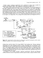
Figure 9.8 shows the basic components of a utility interactive
inverter that meets the requirements of IEEE Standard 929-2000.
5
Direct current is supplied on the left side of the diagram either from a
conversion technology that produces direct current directly or from the
rectification of ac generator output. Variations of this type of inverter
are commonly employed on fuel cells, microturbines, photovoltaic solar
systems, and some wind turbines.
The dc voltage is switched at a very high rate with an insulated gate
bipolar transistor (IGBT) switch to create a sinusoid voltage or current
of power frequency. The switching frequency is typically on the order of
50 to 100 times the power frequency. The filter on the output attenu-
ates these high-frequency components to a degree that they are usually
negligible. However, resonant conditions on the power system can
sometimes make these high frequencies noticeable. The largest low-
order harmonic (usually, the fifth) is generally less than 3 percent, and
Distributed Generation and Power Quality 387
+
DC AC SWITCH FILTER
VOLTAGE
CURRENT
SWITCHING
CONTROL
Figure 9.8 Simplified schematic diagram of a modern switching inverter.
Distributed Generation and Power Quality
Downloaded from Digital Engineering Library @ McGraw-Hill (www.digitalengineeringlibrary.com)
Copyright © 2004 The McGraw-Hill Companies. All rights reserved.
Any use is subject to the Terms of Use as given at the website.
the others are often negligible. The total harmonic distortion limit is 5
percent, based on the requirements of IEEE Standard 519-1992.
Occasionally, some inverters will exceed these limits under specific con-
ditions. Manufacturers may skimp on filtering, or there may be a flaw
in the switch control algorithm. Nevertheless, the harmonic issue with
modern inverters is certainly much less of a concern than those based
on older technologies.
While interconnected to the utility, commonly applied inverters basi-
cally attempt to generate a sine-wave current that follows the voltage
waveform. Thus, they would produce power at unity power factor. It is
possible to program other strategies into the switching control, but the
unity power factor strategy is the simplest and most common. Also, it
allows the full current-carrying capability of the switch to be used for
delivering active power (watts). If the inverter has stand-alone capabil-
ity, the control objective would change to producing a sinusoidal voltage
waveform at power frequency and the current would follow the load.
One of the advantages of such an inverter for DG applications is that
it can be switched off very quickly when trouble is detected. There may
be some lag in determining that something has gone wrong, particu-
larly if there are synchronous machines with substantial inertia main-
taining the voltage on the system. When a disturbance requiring
disconnection is detected, the switching simply ceases. Inverters typi-
cally exhibit very little inertia and changes can take place in millisec-
onds. Rotating machines may require several cycles to respond. It may
be possible to reclose out of phase on inverters without damage pro-
vided current surge limits in the semiconductor switches are not
exceeded. Thus, reconnection and resynchronization are less of an
issue than with synchronous machines.
The ability of inverters to feed utility-side faults is usually limited by
the maximum current capability of the IGBT switches. Analysts com-
monly assume that the current will be limited to 2 times the rated out-
put of the inverter. Of course, once the current reaches these values,
the inverter will likely assume a fault and cease operation for a prede-
termined time. This can be an advantage for utility interactive opera-
tion but can also be a disadvantage for applications requiring a certain
amount of fault current to trip relays.
Utility interactive inverters compliant with IEEE Standard 929-
2000 also have a destabilizing signal that is constantly trying to change
the frequency of the control. The purpose is to help ensure that inad-
vertent islands are promptly detected. While interconnected with the
utility, the strength of the electrical power system overpowers this ten-
dency toward destabilization. If the inverter system is suddenly iso-
lated on load, the frequency will quickly deviate, allowing it to be
detected both within the control and by external relays.
388 Chapter Nine
Distributed Generation and Power Quality
Downloaded from Digital Engineering Library @ McGraw-Hill (www.digitalengineeringlibrary.com)
Copyright © 2004 The McGraw-Hill Companies. All rights reserved.
Any use is subject to the Terms of Use as given at the website.
9.4 Power Quality Issues
The main power quality issues affected by DG are
1. Sustained interruptions. This is the traditional reliability area.
Many generators are designed to provide backup power to the load
in case of power interruption. However, DG has the potential to
increase the number of interruptions in some cases.
2. Voltage regulation. This is often the most limiting factor for how
much DG can be accommodated on a distribution feeder without
making changes.
3. Harmonics. There are harmonics concerns with both rotating
machines and inverters, although concern with inverters is less with
modern technologies.
4. Voltage sags. This a special case because DG may or may not help.
Each of these issues is discussed in turn.
9.4.1 Sustained interruptions
Much of the DG that is already in place was installed as backup gen-
eration. The most common technology used for backup generation is
diesel gensets. The bulk of the capacity of this form of DG can be real-
ized simply by transferring the load to the backup system. However,
there will be additional power that can be extracted by paralleling with
the power system. Many DG installations will operate with better
power quality while paralleled with the utility system because of its
large capacity. However, not all backup DG can be paralleled without
great expense.
Not all DG technologies are capable of significant improvements in
reliability. To achieve improvement, the DG must be capable of serving
the load when the utility system cannot.
For example, a homeowner may install a rooftop photovoltaic solar
system with the expectation of being able to ride through rotating
blackouts. Unfortunately, the less costly systems do not have the
proper inverter and storage capacity to operate stand-alone. Therefore,
there is no improvement in reliability.
Utilities may achieve improved reliability by employing DG to cover
contingencies when part of the delivery system is out of service. In this
case, the DG does not serve all the load, but only enough to cover for the
capacity that is out of service. This can allow deferral of major con-
struction expenses for a few years. The downside is that reliance on this
scheme for too many years can ultimately lead to worse reliability. The
load growth will overtake the base capacity of the system, requiring load
Distributed Generation and Power Quality 389
Distributed Generation and Power Quality
Downloaded from Digital Engineering Library @ McGraw-Hill (www.digitalengineeringlibrary.com)
Copyright © 2004 The McGraw-Hill Companies. All rights reserved.
Any use is subject to the Terms of Use as given at the website.
shedding during peak load conditions or resulting in the inability to
operate the system at acceptable voltage after a fault.
9.4.2 Voltage regulation
It may initially seem that DG should be able to improve the voltage reg-
ulation on a feeder. Generator controls are much faster and smoother
than conventional tap-changing transformers and switched capacitor
banks. With careful engineering, this can be accomplished with suffi-
ciently large DG. However, there are many problems associated with
voltage regulation. In cases where the DG is located relatively far from
the substation for the size of DG, voltage regulation issues are often the
most limiting for being able to accommodate the DG without changes
to the utility system.
It should first be recognized that some technologies are unsuitable
for regulating voltages. This is the case for simple induction machines
and for most utility interactive inverters that produce no reactive
power. Secondly, most utilities do not want the DG to attempt to regu-
late the voltage because that would interfere with utility voltage regu-
lation equipment and increase the chances of supporting an island.
Multiple DG would interfere with each other. Finally, small DG is sim-
ply not powerful enough to regulate the voltage and will be dominated
by the daily voltage changes on the utility system. Small DG is almost
universally required to interconnect with a fixed power factor or fixed
reactive power control.
Large DG greater than 30 percent of the feeder capacity that is set to
regulate the voltage will often require special communications and con-
trol to work properly with the utility voltage-regulating equipment.
One common occurrence is that the DG will take over the voltage-reg-
ulating duties and drive the substation load tap changer (LTC) into a
significant bucking position as the load cycles up and down. This
results in a problem when the DG suddenly disconnects, as it would for
a fault. The voltage is then too low to support the load and takes a
minute or more to recover. One solution is to establish a control scheme
that locks the LTC at a preselected tap when the generator is operat-
ing and interconnected.
Large voltage changes are also possible if there were a significant
penetration of dispersed, smaller DG producing a constant power fac-
tor. Suddenly connecting or disconnecting such generation can result
in a relatively large voltage change that will persist until recognized
by the utility voltage-regulating system. This could be a few minutes,
so the change should be no more than about 5 percent. One condition
that might give rise to this would be fault clearing on the utility sys-
tem. All the generation would disconnect when the fault occurs, wait 5
min, and then reconnect. Customers would first see low voltage for a
390 Chapter Nine
Distributed Generation and Power Quality
Downloaded from Digital Engineering Library @ McGraw-Hill (www.digitalengineeringlibrary.com)
Copyright © 2004 The McGraw-Hill Companies. All rights reserved.
Any use is subject to the Terms of Use as given at the website.
minute, or so, followed 5 min later by high voltages. Options for deal-
ing with this include faster tap-changing voltage regulators and
requiring the load to be disconnected whenever the DG is forced off
due to a disturbance. There is less voltage excursion when the DG is
operating near unity power factor. However, there may be some
instances where it will be advantageous in normal operation to have
the DG produce reactive power.
9.4.3 Harmonics
There are many who still associate DG with bad experiences with har-
monics from electronic power converters. If thyristor-based, line-com-
mutated inverters were still the norm, this would be a large problem.
Fortunately, the technologies requiring inverters have adopted the
switching inverters like the one described previously in this chapter.
This has eliminated the bulk of the harmonics problems from these
technologies.
One problem that occurs infrequently arises when a switching
inverter is installed in a system that is resonant at frequencies pro-
duced by the switching process. The symptom is usually high-fre-
quency hash appearing on the voltage waveform. The usual power
quality complaint, if any, is that clocks supplied by this voltage run fast
at times. This problem is generally solved by adding a capacitor to the
bus that is of sufficient size to shunt off the high-frequency components
without causing additional resonances.
Harmonics from rotating machines are not always negligible, partic-
ularly in grid parallel operation. The utility power system acts as a
short circuit to zero-sequence triplen harmonics in the voltage, which
can result in surprisingly high currents. For grounded wye-wye or
delta-wye service transformers, only synchronous machines with 2/3
pitch can be paralleled without special provisions to limit neutral cur-
rent. For service transformer connections with a delta-connected wind-
ing on the DG side, nearly any type of three-phase alternator can be
paralleled without this harmonic problem.
9.4.4 Voltage sags
The most common power quality problem is a voltage sag, but the abil-
ity of DG to help alleviate sags is very dependent on the type of gener-
ation technology and the interconnection location. Figure 9.9
illustrates a case in which DG is interconnected on the load side of the
service transformer. During a voltage sag, DG might act to counter the
sag. Large rotating machines can help support the voltage magnitudes
and phase relationships. Although not a normal feature, it is conceiv-
able to control an inverter to counteract voltage excursions.
Distributed Generation and Power Quality 391
Distributed Generation and Power Quality
Downloaded from Digital Engineering Library @ McGraw-Hill (www.digitalengineeringlibrary.com)
Copyright © 2004 The McGraw-Hill Companies. All rights reserved.
Any use is subject to the Terms of Use as given at the website.
The DG influence on sags at its own load bus is aided by the imped-
ance of the service transformer, which provides some isolation from the
source of the sag on the utility system. However, this impedance hin-
ders the ability of the DG to provide any relief to other loads on the
same feeder. DG larger than 1 MW will often be required to have its
own service transformer. The point of common coupling with any load
is the primary distribution system. Therefore, it is not likely that DG
connected in this manner will have any impact on the voltage sag char-
acteristic seen by other loads served from the feeder.
9.5 Operating Conflicts
Deploying generation along utility distribution systems naturally cre-
ates some conflicts because the design of the system assumes only one
source of power.
6
A certain amount of generation can be accommodated
without making any changes. At some point, the conflicts will be too
great and changes must be made.
In this section, several of the operating conflicts that can result in
power quality problems are described.
9.5.1 Utility fault-clearing requirements
Figure 9.10 shows the key components of the overcurrent protection
system of a radial feeder.
7
The lowest-level component is the lateral
fuse, and the other devices (reclosers and breakers) are designed to con-
form to the fuse characteristic. There will frequently be two to four
feeders off the same substation bus. This design is based mostly on eco-
nomic concerns. This is the least costly protection scheme that is able
392 Chapter Nine
Figure 9.9 DG may help reduce voltage sags on
local facility bus, but impedance of interconnection
transformer inhibits any impact on adjacent utility
customers.
Distributed Generation and Power Quality
Downloaded from Digital Engineering Library @ McGraw-Hill (www.digitalengineeringlibrary.com)
Copyright © 2004 The McGraw-Hill Companies. All rights reserved.
Any use is subject to the Terms of Use as given at the website.
to achieve acceptable reliability for distributing the power. One essen-
tial characteristic is that only one device has to operate to clear and iso-
late a short circuit, and local intelligence can accomplish the task
satisfactorily. In contrast, faults on the transmission system, which
easily handles generation, usually require at least two breakers to
operate and local intelligence is insufficient in some cases.
In essence, this design is the source of most of the conflicts for inter-
connecting DG with the utility distribution system. Because there is too
much infrastructure in place to consider a totally different distribution
system design to better accommodate DG, the DG must adapt to the way
the utility system works. With only one utility device operating to clear
a fault, all other DG devices must independently detect the fault and sep-
arate to allow the utility protection system to complete the clearing and
isolation process. This is not always simple to do from the information
that can be sensed at the generator. The remainder of this section
describes some of the difficulties that occur. Refer to Chap. 3 for more
details on the fault-clearing process on radial distribution systems.
9.5.2 Reclosing
Reclosing utility breakers after a fault is a very common practice, par-
ticularly throughout North America. Most of the distribution lines are
overhead, and it is common to have temporary faults. Once the current
is interrupted and the arc dispersed, the line insulation is restored.
Reclosing enables the power to be restored to most of the customers
within seconds.
Reclosing presents two special problems with respect to DG:
1. DG must disconnect early in the reclose interval to allow time for
the arc to dissipate so that the reclose will be successful.
Distributed Generation and Power Quality 393
FEEDERS
BREAKER
RECLOSER
FUSED LATERALS
Only this device must operate
to clear fault
Figure 9.10 Typical overcurrent protection of a utility distribution
feeder.
Distributed Generation and Power Quality
Downloaded from Digital Engineering Library @ McGraw-Hill (www.digitalengineeringlibrary.com)
Copyright © 2004 The McGraw-Hill Companies. All rights reserved.
Any use is subject to the Terms of Use as given at the website.