ADOBE ILLUSTRATOR CS2 REVEALED PHẦN 3 ppt
Bạn đang xem bản rút gọn của tài liệu. Xem và tải ngay bản đầy đủ của tài liệu tại đây (2.07 MB, 55 trang )
ILLUSTRATOR 3-6
Drawing and Composing an Illustration
Create new views
1. Open AI 3-1.ai, then save it as Straight Lines.
2. Click the Zoom Tool , then position it at
the upper-left corner of the artboard.
3. Click and drag a selection box that encom-
passes the entire yellow section, as shown
in Figure 3.
The area within the selection box is now
magnified.
4. Click View on the menu bar, then click
New View.
5. Name the new view yellow, then click OK.
6. Press and hold [Spacebar] to access the
Hand Tool , then drag the artboard
upward until you have a view of the entire
pink area.
7. Create a new view of the pink area, and
name it pink.
TIP If you need to adjust your view, you
can quickly switch to a view of the entire
artboard by pressing [Ctrl][0] (Win) or
[0] (Mac), then create a new selection
box with the Zoom Tool.
8. Create a new view of the green area,
named mint.
9. Click View on the menu bar, then click yellow
at the bottom of the menu.
The Illustrator window changes to the
yellow view.
TIP You can change the name of a view by
clicking View on the menu bar, then clicking
Edit Views.
You used the Zoom Tool to magnify an area of the
artboard. You then named and saved the new view of
the artboard. You named and saved two other views.
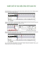
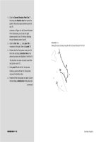
FIGURE 3
Drag the Zoom Tool to select what will be magnified
Selection box
Lesson 1 Draw Straight Lines
ILLUSTRATOR 3-7
Draw straight lines
1. Verify that you are still in the yellow view,
then click the Pen Tool .
2. Set the fill color to [None], the stroke color
to Black, and the stroke weight to 1 pt.
3. Using Figure 4 as a reference, click position
1 (start).
4. Click position 2, then notice the segment
that is automatically drawn between the two
anchor points.
5. Click position 3, then click position 4.
TIP If you become disconnected from the
current path you are drawing, undo your last
step, then click the last anchor point with the
Pen Tool and continue.
6. Press [Ctrl] (Win) or (Mac) to switch to
the Selection Tool , then click the artboard
to stop drawing the path and to deselect it.
You need to deselect one path before you
can start drawing a new one.
7. Click position 1 (start) on the next path,
then click position 2.
8. Skip over position 3 and click position 4.
9. Using Figure 5 as a guide, position the
Pen Tool anywhere on the segment between
points 2 and 4, then click to add a new
anchor point.
TIP When the Pen Tool is positioned over a
selected path, the Add Anchor Point Tool
appears.
10.Click the Direct Selection Tool , then
drag the new anchor point to position 3, as
shown in Figure 6.
Using the Pen Tool, you created two straight paths.
FIGURE 4
Four anchor points and three segments
FIGURE 5
Click the path with the Pen Tool to add a new point
FIGURE 6
Move an anchor point with the Direct Selection Tool
Add Anchor
Point Tool
ILLUSTRATOR 3-8
Drawing and Composing an Illustration
Close a path and align the
anchor points
1. Click View on the menu bar, then click pink.
2. Click the Pen Tool , click the start/end
position at the top of the polygon, then click
positions 2 through 6.
3. Position the Pen Tool over the first point you
created, then click to close the path, as shown
in Figure 7.
4. Switch to the Direct Selection Tool , click
point 3, press and hold [Shift], then click
point 6.
TIP Use the [Shift] key to select
multiple points.
Anchor points that are selected appear as solid
blue squares; anchor points that are not
selected are white or hollow squares.
5. Click Object on the menu bar, point to Path,
then click Average.
6. Click the Horizontal option button in the
Average dialog box, then click OK.
The two selected anchor points align on the
horizontal axis, as shown in Figure 8.
7. Select both the start/end point and point 4.
8. Use the Average command to align the points
on the vertical axis.
9. Select both point 2 and point 5, then use the
Average command to align the points on both
axes, as shown in Figure 9.
You drew a closed path, then used the Average com-
mand to align three sets of points. You aligned the
first set on the horizontal axis, the second on the ver-
tical axis. You aligned the third set of points on both
axes, which positioned them one on top of the other.
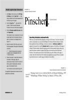
FIGURE 7
Close a path at its starting point
FIGURE 8
Two points aligned on the horizontal axis
FIGURE 9
Averaging two points on both the horizontal and vertical axes
Aligned points
Unaligned points
A small circle appears
next to the Pen Tool when
you position it over the
first anchor point
Lesson 1 Draw Straight Lines
ILLUSTRATOR 3-9
Join anchor points
1. Switch to the mint view of the artboard.
2. Use the Pen Tool to trace the two dia-
mond shapes.
TIP Remember to deselect the first dia-
mond path with the Selection Tool before
you begin tracing the second diamond.
3. Click the left anchor point of the first dia-
mond with the Direct Selection Tool ,
click Edit on the menu bar, then click Cut.
Cutting points also deletes the segments
attached to them.
4. Cut the right point on the second diamond.
Your work should resemble Figure 10.
5. Select the top point on each path.
6. Click Object on the menu bar, point to Path,
then click Join.
The points are joined by a straight segment,
as shown in Figure 11.
TIP The similarity of the quick keys for
Average and Join makes them easy to work
with in tandem.
7. Join the two bottom points.
8. Apply a yellow fill to the object, then save
your work.
Your work should resemble Figure 12.
9. Close the Straight Lines document.
You drew two closed paths. You cut a point from
each path, which deleted the points and the seg-
ments attached to them, creating two open paths.
You used the Join command, which drew a new
segment between the two top points and the two
bottom points on each path. You then applied a
yellow fill to the new object.
FIGURE 10
Cutting points also deletes the segments attached to them
FIGURE 11
Join command unites two distant points with a straight segment
FIGURE 12
Joining the two open anchor points on an open path closes the path
LESSON 2
Defining Properties of
Curved Lines
When you click to create anchor points
with the Pen Tool, the points are con-
nected by straight segments. You can
“draw” a curved path between two anchor
points by clicking and dragging the Pen
Tool to create the points, instead of just
clicking. Anchor points created by clicking
and dragging the Pen Tool are known as
smooth points.
When you use the Direct Selection Tool to
select a point connected to a curved seg-
ment, you will expose the point’s direc-
tion lines, as shown in Figure 13. The
angle and length of the direction lines
determine the arc of the curved segment.
Direction lines are editable. You can click
What You’ll Do
In this lesson, you will use the Pen Tool to
draw and define curved paths, and learn
techniques to draw lines that abruptly
change direction.
▼
ILLUSTRATOR 3-10
Drawing and Composing an Illustration
DRAW
CURVED LINES
Lesson 2 Draw Curved Lines
ILLUSTRATOR 3-11
and drag the direction points at the end
of the direction lines to reshape the curve.
Direction lines function only to define
curves and do not appear when you print
your document.
A smooth point always has two direction
lines that move together as a unit. The two
curved segments attached to the smooth
point are both defined by the direction lines.
When you manipulate the direction lines on
a smooth point, you change the curve of
both segments attached to the point, always
maintaining a smooth transition through
the anchor point.
When two paths are joined at a corner
point, the two paths can be manipulated
independently. A corner point can join
two straight segments, one straight seg-
ment and one curved segment, or two
curved segments. That corner point
would have zero, one, or two direction
lines, respectively. Figure 14 shows
examples of smooth points and corner
points.
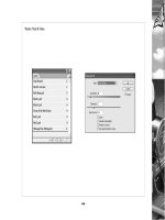
FIGURE 13
Direction lines define a curve
FIGURE 14
Smooth points and corner points
Direction point
Direction line
Smooth anchor point
A corner point joining
two curved paths (note
the direction lines)
A smooth point
A corner point joining
one straight and one
curved segment
A corner point joining
two straight segments
ILLUSTRATOR 3-12
Drawing and Composing an Illustration
When a corner point joins one or two
curved segments, the direction lines are
unrelated and are often referred to as
“broken.” When you manipulate one, the
other doesn’t move.
Converting Anchor Points
The Convert Anchor Point Tool changes
corner points to smooth points and smooth
points to corner points.
To convert a corner point to a smooth
point, you click and drag the Convert
Anchor Point Tool on the anchor point to
pull out direction lines. See Figure 15.
The Convert Anchor Point Tool works two
ways to convert a smooth point to a
corner point, and both are very useful
when drawing.
FIGURE 15
Converting a corner point to a smooth point
Corner point
converted to a
smooth point
Corner point
Lesson 2 Draw Curved Lines
ILLUSTRATOR 3-13
When you click directly on a smooth point
with the Convert Anchor Point Tool, the
direction lines disappear. The two attached
segments lose whatever curve defined them
and become straight segments, as shown in
Figure 16.
You can also use the Convert Anchor Point
Tool on one of the two direction lines of a
smooth point. The tool “breaks” the direc-
tion lines and allows you to move one inde-
pendently of the other. The smooth point is
converted to a corner point that now joins
two unrelated curved segments.
Once the direction lines are broken, they
remain broken. You can manipulate them
independently with the Direct Selection
Tool; you no longer need the Convert
Anchor Point Tool to do so.
FIGURE 16
Converting smooth points to corner points
Smooth point
Corner point
converted to a
smooth point
Smooth point
converted to a
corner point
Toggling between the Pen Tool and the selection tools
Drawing points and selecting points go hand in hand, and you will often switch back
and forth between the Pen Tool and one of the selection tools. Clicking from one
tool to the other in the toolbox is unnecessary and will impede your productivity. To
master the Pen Tool, you must incorporate the keyboard command for “toggling”
between the Pen Tool and the selection tools. With the Pen Tool selected, press
[Ctrl] (Win) or (Mac), which will switch the Pen Tool to the Selection Tool or
the Direct Selection Tool, depending on which tool you used last.
ILLUSTRATOR 3-14
Drawing and Composing an Illustration
Draw and edit a curved line
1. Open AI 3-2.ai, then save it as Curved Lines 1.
2. Click the Pen Tool , then position it over
the first point position on the line.
3. Click and drag upward until the pointer is at
the center of the purple star.
4. Position the Pen Tool over the second point
position.
5. Click and drag down to the red star.
6. Using the same method, trace the remainder
of the blue line, as shown in Figure 17.
7. Click the Direct Selection Tool .
8. Select the second anchor point.
9. Click and drag the direction handle of the
top direction line to the second purple star,
as shown in Figure 18.
The move changes the shape of both seg-
ments attached to the anchor point.
10.Select the third anchor point.
11.Drag the bottom direction handle to the
second red star, as shown in Figure 19.
12.Manipulate the direction lines to restore the
curves to their appearance in Figure 17.
13. Save your work, then close the Curved
Lines 1 document.
You traced a curved line by making smooth points
with the Pen Tool. You used the Direct Selection
Tool to manipulate the direction lines of the
smooth points and adjust the curves. You then
used the direction lines to restore the line to its
original curves.
FIGURE 17
Smooth points draw continuous curves
FIGURE 18
Moving one direction line changes two curves
FIGURE 19
Round curves are distorted by moving direction lines
Click the Direct
Selection Tool on
any smooth point
to expose its
direction lines
FIGURE 21
Smooth points restored from corner points
Lesson 2 Draw Curved Lines
ILLUSTRATOR 3-15
Convert anchor points
1. Open AI 3-3.ai, then save it as Curved Lines 2.
2. Click View on the menu bar, then click
View #1.
3. Click the Direct Selection Tool any-
where on the black line.
Six anchor points become visible.
4. Click Object on the menu bar, point to Path,
then click Add Anchor Points.
Five anchor points are added that do not
change the shape of the line.
5. Click the Convert Anchor Point Tool , then
click each of the five new anchor points.
TIP The Convert Anchor Point Tool is
hidden beneath the Pen Tool.
The smooth points are converted to
corner points, as shown in Figure 20.
6. Click the six original anchor points with the
Convert Anchor Point Tool.
7. Starting from the left side of the line, posi-
tion the Convert Anchor Point Tool over the
sixth anchor point.
8. Click and drag the anchor point to the
purple star.
The corner point is converted to a smooth point.
9. Using Figure 21 as a guide, convert the cor-
ner points to the left and right of the
new curve.
You added five new anchor points to the line, then
used the Convert Anchor Point Tool to convert all
11 points from smooth to corner points. You then
used the Convert Anchor Point Tool to convert
three corner points to smooth points.
FIGURE 20
Smooth points are converted to corner points
ILLUSTRATOR 3-16
Drawing and Composing an Illustration
Draw a line with curved and
straight segments
1. Click View on the menu bar, then click View #2.
2. Click the Pen Tool , position it over the
first point position, then click and drag down
to the green star.
3. Position the Pen Tool over the second point
position, then click and drag up to the
purple star, as shown in the top section of
Figure 22.
4. Click the second anchor point.
The direction line you dragged is deleted, as
shown in the lower section of Figure 22.
5. Click the third point position to create the
third anchor point.
6. Position the Pen Tool over the third anchor
point, then click and drag a direction line up
to the green star.
7. Position the Pen Tool over the fourth point
position, then click and drag down to the
purple star.
8. Click the fourth anchor point.
9. Position the Pen Tool over the fifth position,
then click.
10.While the Pen Tool is still positioned over
the fifth anchor point, click and drag a
direction line down to the green star.
11.Finish tracing the line, then deselect the path.
You traced a line that has three curves joined by
two straight segments. You used the technique of
clicking the previous smooth point to convert it to
a corner point, allowing you to change the
direction of the path.
FIGURE 22
Click to convert an open smooth point to a corner point
Direction line
is deleted
Clicking the last smooth
point you drew converts it to
a corner point
First position
point
Lesson 2 Draw Curved Lines
ILLUSTRATOR 3-17
Reverse direction while
drawing
1. Click View on the menu bar, then click
View #3.
2. Click the Pen Tool position it over the
first point position, then click and drag down
to the purple star.
3. Position the Pen Tool over the second
point position, then click and drag up to the
red star, as shown in the top section of
Figure 23.
4. Press and hold [Alt] (Win) or [option] (Mac)
to switch to the Convert Anchor Point Tool ,
then click and drag the direction handle on
the red star down to the second purple star, as
shown in the lower section of Figure 23.
TIP Press [Alt] (Win) or [option] (Mac) to
toggle between the Pen and the Convert
Anchor Point Tools.
5. Release [Alt] (Win) or [option] (Mac),
then continue to trace the line using the
same method.
TIP If you switch between the PenTool and
the Convert Anchor Point Tool using the
toolbox, instead of using [Alt] (Win) or
[option] (Mac), you will disconnect from the
current path.
6. Save your work, then close the Curved Lines 2
document.
You used the Convert Anchor Point Tool to “break”
the direction lines of a smooth point, converting it
to a corner point in the process. You used the
redirected direction line to define the next curve in
the sequence.
FIGURE 23
Use the Convert Anchor Point Tool to “break” the direction lines and redirect the path
LESSON 3
Starting an Illustration
Getting started with drawing an illustra-
tion is often the hardest part. Sometimes
the illustration will be an image of a well-
known object or a supplied sketch or a pic-
ture. At other times, the illustration to be
created will exist only in your imagination.
In either case, the challenge is the same:
How do you translate the concept from its
source to the Illustrator artboard?
Drawing from Scratch
Drawing from scratch means that you
start with a new Illustrator document and
create the illustration, using only the
Illustrator tools. This approach is com-
mon, especially when the goal is to draw
familiar items such as a daisy, a fish, or the
sun, for example.
Illustrator’s shape tools (such as the Ellipse
Tool) combined with the transform tools
(such as the Rotate Tool) make the pro-
gram very powerful for creating geometric
designs from scratch. The Undo and Redo
commands allow you to experiment, and
you will often find yourself surprised by the
design you end up with!
Typographic illustrations—even complex
ones—are often created from scratch.
Many talented illustrators and designers
are able to create complex graphics off the
cuff. It can be an astounding experience to
watch an illustrator start with a blank art-
board and, with no reference material,
produce sophisticated graphics—graphics
with attitude and expression and emotion,
with unexpected shapes and subtle rela-
tionships between objects.
Tracing a Scanned Image
Using the Place command, it is easy to
import a scanned image into Illustrator.
For complex illustrations—especially those
of people or objects with delicate relation-
ships, such as maps or blueprints—many
designers find it easier to scan a sketch or a
photo and import it into Illustrator as a
guide or a point of reference.
What You’ll Do
In this lesson, you will draw 14 elements
of an illustration. By tracing previously
drawn elements, you will develop a sense
of where to place anchor points when
drawing a real-world illustration.
▼
ILLUSTRATOR 3-18
Drawing and Composing an Illustration
DRAW ELEMENTS OF
AN ILLUSTRATION
Tracing a scanned image is not “cheating.”
An original drawing is an original drawing,
whether it is first created on a computer or
on a piece of paper. Rather than being a
negative, the ability to use a computer to
render a sketch is a fine example of the rev-
olutionary techniques that illustration soft-
ware has brought to the art of drawing.
Figure 24 shows an illustration created
from scratch in Illustrator, and Figure 25
shows a scanned sketch that will be the
basis for the illustration you will create
throughout this chapter.
FIGURE 24
An illustration created from scratch
Lesson 3 Draw Elements of an Illustration
ILLUSTRATOR 3-19
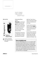
FIGURE 25
Place a scanned sketch in Illustrator, and you can trace it or use it as a visual reference
FIGURE 26
Points 1 through 6 are smooth points
When closing a path, pressing
[Alt] (Win) or [option] (Mac)
converts the end/start anchor
point to a corner point
ILLUSTRATOR 3-20
Drawing and Composing an Illustration
Draw a closed path using
smooth points
1. Open AI 3-4.ai, then save it as Snowball Parts.
2. Click View on the menu bar, then click Arm.
3. Verify that the fill color is set to [None] and
the stroke color is set to Black.
4. Click the Pen Tool , position it over point 1,
then click and drag a direction line to the green
star on the right side of the 1.
5. Go to position 2, then click and drag a
direction line to the next green star.
TIP Watch the blue preview of the new seg-
ment fall into place as you drag the Pen
Tool. This will help you understand when to
stop dragging the direction line.
6. Using the same method, continue to draw
points 3 through 6, then compare your
screen to Figure 26.
7. Position the Pen Tool over point 1.
8. Press and hold [Alt] (Win) or [option] (Mac),
then click and drag to position the ending seg-
ment and close the path.
You drew a curved path. To close the path, you
used a corner point, which allowed you to position
the ending segment without affecting the starting
segment.
FIGURE 27
Point 5 is a corner point
Corner point
Lesson 3 Draw Elements of an Illustration
ILLUSTRATOR 3-21
Begin and end a path with a
corner point
1. Click View on the menu bar, then click
Hatband.
2. Verify that the fill color is set to [None] and
the stroke color is set to Black.
3. Click the Pen Tool , then click position 1
to create a corner point.
4. Draw the next two curved segments for
positions 2 and 3, using the green stars
as guides.
5. Position the Pen Tool over position 4, then
click and drag to the green star.
6. Click position 5 to create a corner point, as
shown in Figure 27.
7. Position the Pen Tool over position 6, then
click and drag to the green star.
8. Click position 1 to close the path with a
corner point.
9. Click the Selection Tool , then deselect
the path.
You began a path with a corner point. When it was
time to close the path, you simply clicked the
starting point. Since the point was created without
direction lines, there were no direction lines to
contend with when closing the path.
FIGURE 28
Use the Convert Anchor Point Tool to redirect the path
ILLUSTRATOR 3-22
Drawing and Composing an Illustration
Redirect a path while
drawing
1. Click View on the menu bar, then click Nose.
The Nose view includes the nose, mouth,
eyebrow, and teeth.
2. Click the Pen Tool , then click point 1 on
the nose to start the path with a corner point.
3. Create smooth points at positions 2 and 3.
The direction of the nose that you are tracing
abruptly changes at point 3.
4. Press and hold [Alt] (Win) or [option] (Mac) to
switch to the Convert Anchor Point Tool ,
then move the top direction handle of point 3
down to the red star, as shown in Figure 28.
5. Release [Alt] (Win) or [option] (Mac) to
switch back to the Pen Tool, click and drag
position 4 to finish drawing the path, click the
Selection Tool , then deselect the path.
The nose element, as shown in Figure 29, is
an open path.
Tracing the nose, you encountered an abrupt
change in direction, followed by a curve. You used
the Convert Anchor Point Tool to redirect the
direction lines on point 3, simultaneously convert-
ing point 3 from smooth to corner and defining the
shape of the curved segment that follows.
FIGURE 29
Nose element is an open path
Lesson 3 Draw Elements of an Illustration
ILLUSTRATOR 3-23
Place a scanned image
1. Click View on the menu bar, then click Fit
in Window.
2. Click File on the menu bar, then click Place.
3. Navigate to the drive and folder where your
Data Files are stored.
4. Click Snowball Sketch.tif, then click Place.
A scan of the Snowball Sketch illustration is
placed in a bounding box at the center of the
artboard.
5. Use the Scale Tool to scale the placed
file 115%.
TIP You can apply all of the transform tools
to placed files.
6. Click the Selection Tool , move the placed
file into the scratch area, then lock it.
7. Draw the remaining elements of the illustra-
tion, referring to the sketch in the scratch
area or to Figure 30 for help.
TIP The mouth, eyebrow, and teeth are
located in the Nose view.
8. Save your work after you complete each
element.
You placed a file of a scanned sketch to use as a
reference guide. You scaled the object, dragged it
to the scratch area, locked it, then drew the
remaining elements of the illustration.
FIGURE 30
Use a scanned sketch as a reference or for tracing
LESSON 4
Using the Eyedropper Tool
Illustrator uses the word attributes to
refer to that which has been applied to an
object that affects its appearance.
Typographic attributes, for example, would
include font, leading, horizontal scale, etc.
Artistic attributes include the fill color,
stroke color, and stroke weight.
The Eyedropper Tool is handy for applying
all of an object’s attributes to another
object. Its icon is particularly apt: The
Eyedropper Tool “picks up” an object’s
attributes, such as fill color, stroke color,
and stroke weight.
QUICKTIP
You can think of the Eyedropper Tool as taking a sample of
an object’s attributes.
The Eyedropper Tool is particularly useful
when you want to apply one object’s attrib-
utes to another. For example, if you have
appplied a blue fill with a 3.5 pt orange
stroke to an object, you can easily apply
those attributes to new or already-existing
objects. Simply select the object that you
want to format, then click the formatted
object with the Eyedropper Tool.
This is a simple example, but don’t under-
estimate the power of the Eyedropper Tool.
As you explore more of Illustrator, you will
find that you are able to apply a variety of
increasingly complex attributes to objects.
The more – and more complex – the attrib-
utes, the more the Eyedropper Tool reveals
its usefulness.
You can also use the Eyedropper Tool
to copy type formatting and effects
between text elements. This can be
especially useful when designing display
type for headlines.
What You’ll Do
You will create four new colors in the
Color palette and apply each to one of the
illustration elements. Using the
Eyedropper Tool, you will paint the
remaining items quickly and easily.
▼
ILLUSTRATOR 3-24
Drawing and Composing an Illustration
APPLY ATTRIBUTES
TO OBJECTS
Lesson 4 Apply Attributes to Objects
ILLUSTRATOR 3-25
FIGURE 31
A fill color applied to an open path
Adding a Fill to an Open Path
You can think of the letter O as an exam-
ple of a closed path and the letter U as an
example of an open path. Although it
seems a bit strange, you are able to add a
fill to an open path just as you would to a
closed path. The program draws an imagi-
nary straight line between the endpoints
of an open path to define where the fill
ends. Figure 31 shows an open path in the
shape of a U with a red fill. Note where
the fill ends. For the most part, avoid
applying fills to open paths. Though
Illustrator will apply the fill, an open
path’s primary role is to feature a stroke.
Any effect that you can create by filling an
open path you can also create with a more
effective method by filling a closed path.
ILLUSTRATOR 3-26
Drawing and Composing an Illustration
Apply new attributes to open
and closed paths
1. Verify that nothing is selected on the artboard.
2. Create a royal blue color in the Color palette.
3. Fill the arm with the royal blue color, then
change its stroke weight to 6 pt.
TIP Use the views at the bottom of the
View menu to see and select each element
you need to work with. The mouth, eyebrow,
and teeth are located in the Nose view.
4. Deselect the arm, then create a deep red
color in the Color palette.
5. Fill the hatband with the deep red color, then
change its stroke weight to 3 pt.
6. Deselect the hatband, then create a flesh-
toned color in the Color palette that is 20%
magenta and 56% yellow.
7. Fill the head with the flesh tone; don’t
change the stroke weight.
8. Fill the pompom with White; don’t change
the stroke weight.
9. Fill the mouth with Black; don’t change
the stroke weight.
10.Compare your work with Figure 32.
You applied new attributes to five closed paths
by creating three new colors, using them as fills, then
changing the stroke weight on two of the objects.
FIGURE 32
New attributes applied to five elements
Lesson 4 Apply Attributes to Objects
ILLUSTRATOR 3-27
Copy attributes with the
Eyedropper Tool
1. Select the torso.
2. Click the Eyedropper Tool , then click
the blue arm.
As shown in Figure 33, the torso takes on the
same fill and stroke attributes as the arm.
3. Switch to the Selection Tool , select the
hat, click the Eyedropper Tool then
click the hatband.
4. Using any method you like, fill and stroke
the remaining objects using the colors
shown in Figure 34.
You applied the same attributes from one object
to another by first selecting the object you
wanted to apply the attributes to, then clicking
the object with the desired attributes, using the
Eyedropper Tool.
FIGURE 33
Use the Eyedropper Tool to apply the attributes of one object to another . . . with one click!
Click
Selected
FIGURE 34
All elements ready to be assembled
LESSON 5
Assembling an Illustration
Illustrator’s basic stacking order design is
sophisticated enough to compose any
illustration. Assembling an illustration
with multiple objects will test your fluency
with the stacking order commands: Bring
to Front, Send to Back, Bring Forward,
Send Backward, Paste in Front, Paste in
Back, Group, Lock, Unlock All, Hide, and
Show All. The sequence in which you draw
the elements determines the stacking
order (newer elements are in front of older
ones), so you’ll almost certainly need to
adjust the stacking order when assembling
the elements. Locking and hiding placed
elements will help you to protect the ele-
ments when they are positioned correctly.
What You’ll Do
In this lesson, you will arrange the ele-
ments that you drew in Lesson 4 to create
a composed illustration.
▼
ILLUSTRATOR 3-28
Drawing and Composing an Illustration
FIGURE 35
Eye positioned on the head
FIGURE 36
Second eye is a copy of the first
ASSEMBLE AN
ILLUSTRATION
Lesson 5 Assemble an Illustration
ILLUSTRATOR 3-29
Assemble the illustration
1. Select and copy all the elements on the
artboard.
2. Create a new CMYK Color document that is
9" × 9", then save it as Snowball Assembled.
3. Paste the copied elements into the Snowball
Assembled document.
4. Deselect all objects, select the head, click
Object on the menu bar, point to Arrange,
then click Send to Back.
5. Group the eye and the iris, then position the
eye on the head as shown in Figure 35.
6. Click the eye, press [Alt] (Win) or [option]
(Mac), then drag to create a copy of it, as
shown in Figure 36.
7. Position the nose on the face, cut the nose,
select the left eye, then paste in front.
The nose is pasted in the same position, but
now it is in front of the eye, as shown in
Figure 37.
8. Select the teeth, then bring them to the front.
9. Position the teeth over the mouth, then
group them.
10.Position the mouth and the teeth on the
head, and the eyebrow over the right eye, as
shown in Figure 38.
11.Finish assembling the illustration, using
Figure 39 as a guide, then save your work.
TIP Use the Object menu and the Arrange
menu command to change the stacking
order of objects, as necessary.
You assembled the illustration, utilizing various
commands to change the stacking order of the
individual elements.
FIGURE 37
Nose pasted in front of the left eye
FIGURE 38
Eyebrow positioned over the right eye
FIGURE 39
All elements in position
The nose behind
the left eye
The nose in front
of the left eye
FIGURE 40
Stroke palette
LESSON 6
Defining Joins and Caps
In addition to applying a stroke weight,
you use the Stroke palette to define other
stroke attributes, including joins and caps,
and whether a stroke is solid or dashed.
Figure 40 shows the Dashed Line utility in
the Stroke palette.
Caps are applied to the ends of stroked
paths. The Stroke palette offers three
choices: Butt Cap, Round Cap, and
Projecting Cap. Choose Butt Cap for
squared ends and Round Cap for rounded
ends. Generally, round caps are more
appealing to the eye.
The projecting cap applies a squared edge
that extends the anchor point at a distance
that is one-half the weight of the stroke.
With a projecting cap, the weight of the
stroke is equal in all directions around the
line. The projecting cap is useful when you
align two anchor points at a right angle, as
shown in Figure 41.
What You’ll Do
In this lesson, you will experiment with
strokes of varying weight and attributes,
using options in the Stroke palette. You
will then apply pseudo-strokes to all of the
objects to create dramatic stroke effects.
▼
ILLUSTRATOR 3-30
Drawing and Composing an Illustration
FIGURE 41
Projecting caps are useful when segments meet at right angles
Miter Limit
text box
Two segments
with butt caps
Two segments with
projecting caps
Dash width
text box
Gap width
text box
STROKE OBJECTS FOR
ARTISTIC EFFECT