ADOBE ILLUSTRATOR CS2 REVEALED PHẦN 6 doc
Bạn đang xem bản rút gọn của tài liệu. Xem và tải ngay bản đầy đủ của tài liệu tại đây (2.1 MB, 48 trang )
ILLUSTRATOR 7-8
Working with Filters, Gradient Meshes, Envelopes, and Blends
Saturate and desaturate an
illustration
1. Open AI 7-2.ai, then save it as Saturation.
2. Select all, click View on the menu bar, then
click Hide Edges.
3. Click Filter on the menu bar, point to Colors,
then click Saturate.
4. Click the Preview check box, drag the
Intensity slider all the way to the right,
then click OK.
Your work should resemble Figure 8.
5. Click Filter on the menu bar, point to Colors,
then click Convert to Grayscale.
Every object is filled with a shade of gray, as
shown in Figure 9.
6. Click View on the menu bar, then click
Show Edges.
7. Deselect all by clicking the artboard.
8. Save your work, then close the Saturation
document.
You used the Saturate filter to intensify the color
of an image. You then used the Convert to
Grayscale filter to remove all chromatic color from
the illustration, thereby creating the effect of a
black-and-white image.
FIGURE 8
Illustration with saturated colors
FIGURE 9
Illustration with the Convert to Grayscale filter applied
Lesson 1 Work with Filters
ILLUSTRATOR 7-9
Apply the Pucker & Bloat and
Twist filters
1. Open AI 7-3.ai, then save it as Pucker
and Bloat.
2. Select the large orange square, click Filter
on the menu bar, point to the first Distort
menu, then click Pucker & Bloat.
3. Type 85 in the text box, then click OK.
TIP A positive value produces a bloat
effect; a negative value produces a
pucker effect.
4. Select the gray circle, click Object on the
menu bar, point to Path, then click Add
Anchor Points.
5. Click Filter on the menu bar, then click
Pucker & Bloat at the top of the Filter menu.
The Pucker & Bloat dialog box opens with
the settings last used.
6. Type -75, then click OK.
Your work should resemble Figure 10.
7. Select the blue circle, then apply the Add
Anchor Points command twice.
8. Open the Pucker & Bloat dialog box, type
180 in the text box, then click OK.
9. Click Filter on the menu bar, point to the
first Distort menu, then click Twist.
10.Type 90 in the Angle text box, then click OK.
Your work should resemble Figure 11.
11.Save your work, then close the Pucker and
Bloat document.
You applied the Pucker & Bloat filter in varying
degrees to each object, producing three distinctly
different effects. You also applied the Twist filter.
FIGURE 10
The orange shape is bloated, the gray is puckered
FIGURE 11
The blue circle with added anchor points and the Bloat and Twist filters applied
Bloat
Pucker
Bloat & Twist
LESSON 2
Working with a Mesh Object
The Mesh Tool and the Create Gradient
Mesh command can be used to transform
a basic object into a mesh object. A mesh
object is a single, multicolored object in
which colors can flow in different direc-
tions, and colors transition gradually from
point to point. Meshes exceed the ability of
simple radial and linear gradients for
applying color blends to objects and are
very effective for adding contrast and
dimension.
When you create a mesh object, multiple
mesh lines crisscross the object, joined
at their intersections by mesh points.
Mesh points are diamond-shaped and
work just like anchor points, with the
added functionality of being able to be
assigned a color. When you assign a color
to a mesh point, the color gradates out-
ward from the point.
The area between four mesh points is a
mesh patch. You can apply color to all
four mesh points simultaneously by apply-
ing the color to the patch. Work with this
method to apply broad color changes to
the object.
Mesh points can be added, deleted, and
moved along the mesh line without alter-
ing the shape of the mesh.
Anchor points are also part of the mesh,
and they function as they do on simple
paths. Just as with simple paths, you
can manipulate the anchor points’
direction lines to alter the shape of the
mesh. Figure 12 shows an example of a
mesh object.
Creating a Mesh Object
You can create a mesh object from any
path. You cannot create a mesh object
from compound paths or text objects. You
can create a mesh object with the Mesh
Tool or by applying the Create Gradient
Mesh command.
Generally, you’ll be happiest using the
Create Gradient Mesh command, which
What You’ll Do
In this lesson, you will create and manipu-
late a gradient mesh to add dimension to
basic shapes.
▼
ILLUSTRATOR 7-10
Working with Filters, Gradient Meshes, Envelopes, and Blends
WORK WITH
GRADIENT MESHES
Lesson 2 Work with Gradient Meshes
ILLUSTRATOR 7-11
creates a mesh object with regularly spaced
mesh lines and mesh points. The Create
Gradient Mesh dialog box is shown in
Figure 13. The Mesh Tool adds a mesh
point and its intersecting mesh lines where
you click. The tool is most effective when
you want to add a particular mesh point
(say, for a highlight) to an existing mesh.
The Create Gradient Mesh command is
always the best choice when converting
complex objects.
Once a mesh object has been created, it can-
not be converted back into a simple path.
Complex mesh objects are a memory drain
and may affect your computer’s perform-
ance. When creating mesh objects, keep in
mind that it’s better to create a few simple
mesh objects than a single complex one.
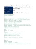
FIGURE 12
Elements of a mesh object
FIGURE 13
Create Gradient Mesh dialog box
Mesh line
Mesh point (with
red applied)
Mesh patch (with
yellow applied)
Direction lines
ILLUSTRATOR 7-12
Working with Filters, Gradient Meshes, Envelopes, and Blends
Create a gradient mesh
1. Open AI 7-4.ai, then save it as Circle Mesh.
2. Select the circle, click Object on the menu
bar, then click Create Gradient Mesh.
3. Type 2 in the Rows text box and 2 in the
Columns text box, then click OK.
4. Deselect, then click the edge of the circle
with the Direct Selection Tool .
5. Select the center mesh point, then click a
yellow swatch in the Swatches palette.
6. Move the center mesh point to the green X,
as shown in Figure 14.
7. Move the direction lines at the top, bottom,
left, and right of the circle’s edge, as shown
in Figure 15.
(continued)
FIGURE 14
Mesh points can be moved, just like anchor points
FIGURE 15
The shape of the mesh is manipulated by direction lines
Lesson 2 Work with Gradient Meshes
ILLUSTRATOR 7-13
8. Click the Mesh Tool , then click the blue X.
TIP Press [Shift] while you click the Mesh
Tool to add a mesh point without changing
to the current fill color.
9. Click the white swatch in the Swatches
palette to change the color of the mesh point
to white.
10.Click the Selection Tool , deselect, then
hide Layer 2.
Your work should resemble Figure 16.
11.Save your work, then close the Circle Mesh
document.
You applied a gradient mesh to a circle with the
Create Gradient Mesh command, changed the
color of a mesh point, then moved the mesh point.
You then used the Mesh Tool to expand the mesh.
You changed the color of the new mesh point to
white to add a highlight to the sphere.
FIGURE 16
Gradient meshes add dimension to an object
ILLUSTRATOR 7-14
Working with Filters, Gradient Meshes, Envelopes, and Blends
FIGURE 17
Selecting a mesh point
FIGURE 18
Mesh points can be moved without changing the shape of the mesh
Upper-left
mesh point
A mesh point
relocated on a
mesh line
Manipulate a gradient mesh
1. Open AI 7-5.ai, then save it as Heart Mesh.
2. Select the heart, click Object on the menu
bar, then click Create Gradient Mesh.
3. Type 4 in the Rows text box and 4 in the
Columns text box, then click OK.
4. Deselect, then click the edge of the heart
with the Direct Selection Tool .
5. Click the upper-left mesh point, as shown in
Figure 17, then change the mesh point color
to 10% black, using the Color palette.
mesh point.
6. Click the Mesh Tool .
7. Press and hold [Shift], then drag the mesh
point along the mesh path to the left, as
shown in Figure 18.
(continued)
Lesson 2 Work with Gradient Meshes
ILLUSTRATOR 7-15
8. Repeat Steps 5-7 for the upper-right mesh
point, then deselect so that your work
resembles Figure 19.
9. Click the Direct Selection Tool , press
and hold [Shift], then select the 20 mesh
points and anchor points along the edge of
the heart.
TIP Mesh points appear as diamonds and
have the same properties as anchor points,
with the added capability of accepting color.
10.Apply a black fill to the selected mesh points.
The selected anchor points are unaffected.
Your work should resemble Figure 20.
11.Deselect, then select the three mesh points
at the lower third of the heart, then apply a
60% black fill so that your work resembles
Figure 21.
12.Select the mesh point at the center of the
heart (between the two 10% black
highlights).
compare your work to Figure 22.
14.Save your work, then close the Heart Mesh
document.
You applied a gradient mesh to a heart shape,
then created highlights by changing the color of
two mesh points. Next, you relocated the high-
light mesh points without changing the shape of
other mesh points to add contrast and dimension
to the artwork.
FIGURE 19
The mesh, reconfigured on both sides of the object
FIGURE 20
Selecting mesh points
Mesh points at the
edge of the object
are filled with black
FIGURE 21
Mesh points are like anchor points, with the added functionality of accepting color assignments
Three interior
mesh points,
darkened
FIGURE 22
Meshes offer the ability to manipulate gradients precisely
What You’ll Do
ILLUSTRATOR 7-16
Working with Filters, Gradient Meshes, Envelopes, and Blends
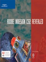
FIGURE 23
An envelope created using a top object
LESSON 3
Defining Envelopes
Envelopes are objects that are used to
distort other selected objects; the dis-
torted objects take on the shape of the
envelope object.
Imagine that you have purchased a basket-
ball as a gift, and you want to wrap it with
paper that has a polka-dot pattern. If these
were objects in Illustrator, the basketball
would be the envelope object, and the
sheet of wrapping paper would be the
object to be distorted. Figure 23 is a good
example of what an envelope distortion
looks like.
You can make envelopes with objects that
you create, or you can use a preset warp
shape or a mesh object as an envelope.
You can use envelopes with compound
paths, text objects, meshes, and blends.
Powerful effects can be achieved by apply-
ing envelopes to linear gradient fills or
pattern fills.
In this lesson, you will create envelope
distortions in three ways: using a top
object, using a mesh, and using a warp.
▼
Resulting
envelope effect
Object to be used
as an envelope
Objects to be
distorted
WORK WITH
ENVELOPES
Lesson 3 Work with Envelopes
ILLUSTRATOR 7-17
Creating Envelopes with Top
Objects, Meshes, and Warps
You create an envelope by using the
Envelope Distort command on the Object
menu. The Envelope Distort command
offers you three options for creating an
envelope: Make with Warp, Make with
Mesh, and Make with Top Object. The top
object is the topmost selected object. Warps
are simply 15 premade shapes to choose
from, to use as your top object. Warps are
especially useful when you don’t want to
draw your own top object. The envelope in
Figure 24 was created using the Flag warp.
Meshes are the same as gradient meshes
made with the Mesh Tool. Creating an
envelope with a mesh allows you to apply a
mesh to multiple objects, which is not the
case when you create a mesh using the
Create Gradient Mesh command or the
Mesh Tool. The envelope in Figure 25 was
created using a mesh.
Applying Envelopes to
Gradient and Pattern Fills
Envelopes can be used to distort objects
that have linear gradient fills or pattern
fills, but you must first activate the option
to do so. In the Envelope Options dialog
box, you can check the Distort Linear
Gradients or Distort Pattern Fills check box
to apply an envelope to either of the fills.
Figure 26 shows the options in the
Envelope Options dialog box.
FIGURE 24
An envelope created using a warp
FIGURE 25
An envelope created using a mesh
FIGURE 26
Envelope Options dialog box
Select to distort
linear gradients
Select to distort
pattern fills
ILLUSTRATOR 7-18
Working with Filters, Gradient Meshes, Envelopes, and Blends
Create an envelope distortion
with a top object
1. Open AI 7-6.ai, then save it as Envelope
Top Object.
2. Copy the yellow circle, paste in front, then
hide the copy.
3. Select all, click Object on the menu bar,
point to Envelope Distort, then click Make
with Top Object.
Your work should resemble Figure 27.
4. Show all, then fill the yellow circle with the
Purple Berry gradient in the Swatches
palette.
5. Send the circle to the back, so that your
work resembles Figure 28.
6. Save your work, then close the Envelope Top
Object document.
You used a circle as the top object in an envelope
distortion. Because you cannot apply a fill to the
circle after it’s been used to make the envelope,
you filled a copy of the circle with a gradient, then
positioned it behind the distorted objects to
achieve the effect.
FIGURE 27
A round envelope distorting a flat star pattern
FIGURE 28
A radial blend enhancing the effect of an envelope distortion
Lesson 3 Work with Envelopes
ILLUSTRATOR 7-19
Create an envelope distortion
with a mesh
1. Open AI 7-7.ai, then save it as Envelope Mesh.
2. Select all, click Object on the menu bar,
point to Envelope Distort, then click Make
with Mesh.
3. Type 4 in the Rows text box and 4 in the
Columns text box, then click OK.
There are five mesh points on each
horizontal line.
4. Deselect, then select the second and fourth
column of mesh points, using the Direct
Selection Tool , as shown in Figure 29.
5. Press and hold [Shift], press two times,
then release [Shift].
Pressing an arrow key in conjunction with
[Shift] moves a selected item ten keyboard
increments.
TIP The keyboard increment value can be
adjusted in the General Preferences dialog box.
6. Select the middle column of mesh points.
7. Press and hold [Shift], press two times,
deselect, then compare your screen to
Figure 30.
8. Save your work, then close the Envelope
Mesh document.
You applied an envelope distortion with a mesh to
a series of rectangles, then moved the mesh points
to create a wave effect.
FIGURE 29
Two columns of mesh points, selected
FIGURE 30
An envelope distortion created using a mesh
Select all of the
mesh points in
the second and
fourth columns
ILLUSTRATOR 7-20
Working with Filters, Gradient Meshes, Envelopes, and Blends
Create an envelope distortion
with a warp effect
1. Open AI 7-8.ai, then save it as Envelope Warp.
2. Select all, click Object on the menu bar,
point to Envelope Distort, then click Make
with Warp.
3. Click the Style list arrow, click Fish, then
click OK.
Your screen should resemble Figure 31.
4. Undo the distort, then make Layer 2 visible.
5. Select all.
(continued)
FIGURE 31
An envelope distortion created using a warp
Lesson 3 Work with Envelopes
ILLUSTRATOR 7-21
6. Click Object on the menu bar, point to
Envelope Distort, then click Make with
Top Object.
As shown in Figure 32, you get the same
result as you did using the fish-style warp.
The reason for this is that using the
Envelope Distort feature with a warp is the
same as using the feature with a top
object—the difference is that warps are pre-
made shapes that you can choose, instead of
making your own.
7. Save your work, then close the Envelope
Warp document.
You applied an envelope distortion with a warp
effect—in this case, the Fish warp. You then used
an object in the shape of the Fish warp as the top
object in a new envelope, with the same result as
in the first distortion. Through this comparison,
you got a better sense of how Illustrator creates
warp effects with envelopes.
Printing color blends and gradient meshes
Print and prepress professionals have long known that some output devices have
trouble printing color blends. The most common problem is banding, an effect in
which the transitions of the gradient are visibly harsh rather than smooth. This prob-
lem was especially common on early PostScript devices. In addition, gradient meshes
(which are a newer feature in Illustrator) may print incorrectly, even on PostScript
Level 3 printers. If you are having trouble outputting either color blends or meshes,
you can print them as bitmaps instead of vectors. To do so, display the Flattener
Preview palette, choose settings in the palette, then save the preset with a descriptive
name by clicking the Flattener Preview palette list arrow, then clicking the Save
Transparency Flattener Preset. When you are ready to print your document, click File
on the menu bar, click Print, click the Advanced category on the left side of the Print
dialog box, select the Print as Bitmap check box, choose your named preset from the
Preset list arrow, then click Print. Anyone who has experience with printing bitmaps
knows that the quality can vary greatly. Use this option only if you are having prob-
lems, then decide if the output is acceptable. If not, you may need to go to a profes-
sional prepress department to output the file.
FIGURE 32
An envelope distortion using a premade shape
What You’ll Do
ILLUSTRATOR 7-22
Working with Filters, Gradient Meshes, Envelopes, and Blends
LESSON 4
Defining a Blend
A blend is a series of intermediate objects
and colors between two or more selected
objects. If the selected objects differ in
color—if they have different fills, for
example—the intermediate objects will be
filled with intermediate colors. Therefore,
in a blend, both shapes and colors are
“blended.” Figure 33 is an example of a
blend using shapes and colors.
Blends are created with either the Blend
Tool or the Make Blend command. You
can make blends between two open paths,
such as two different lines. You can make
blends between two closed paths, such as
a square and a star. You can blend
between objects filled with gradients. You
can even blend between blends, as shown
in Figure 34.
In this lesson, you will use blends to
manipulate shapes and colors for
various effects.
▼
FIGURE 33
In a blend, both shapes and colors are blended
CREATE
BLENDS
Lesson 4 Create Blends
ILLUSTRATOR 7-23
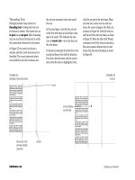
Specifying the Number of
Steps in a Blend
The fewer the number of steps in a blend,
the more distinct each intermediary
object will be. At a greater number of
steps, the intermediate objects become
indistinguishable from one another, and
the blend creates the illusion of being
continuous or “smooth.”
In the Blend Options dialog box, select
from the following options for specifying
the number of steps within a blend.
■ Specified Steps. Enter a value that
determines the number of steps
between the start and the end of
the blend.
■ Specified Distance. Enter a value to
determine the distance between the
steps in the blend. The distance is
measured from the edge of one
object to the corresponding edge on
the next object.
■ Smooth Color. Illustrator determines
the number of steps for the blend, cal-
culated to provide the minimum num-
ber of steps for a smooth color
transition. This is the default option,
which poses a bit of a problem in that
the minimum number of steps will not
always give you the effect you desire, as
shown in Figure 35.
FIGURE 34
A blend between blends
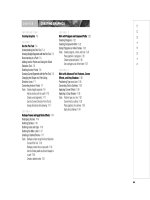
FIGURE 35
Sometimes, the Smooth Color option doesn’t produce the blend effect you desire
Blend #3
Blend #2
Blend #1
A blend between the same
two colors, made with 256
specified steps
A blend between two
similar colors, made
with the Smooth
Color blend option
ILLUSTRATOR 7-24
Working with Filters, Gradient Meshes, Envelopes, and Blends
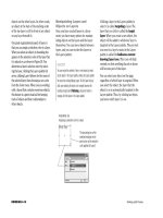
FIGURE 36
Manipulating the blend’s spine changes the blend
An anchor point
added to the spine
of a blend
Altering the spine
alters the blend
Manipulating Blends
Once a blend is created, you can change
its appearance by making changes to one
or more of the original objects. For exam-
ple, using the Direct Selection Tool, you
can select one of the original objects,
then change its fill color, stroke color, or
stroke weight. Illustrator will automati-
cally update the appearance of the steps
to reflect newly added attributes, thus
changing the appearance of the entire
blend. You can also change a blend by
transforming one or more of the original
objects, for example by scaling, rotating,
or moving them.
You can affect the appearance of a blend by
manipulating its spine. When a blend is
created, a path is drawn between the start-
ing and ending objects. Illustrator refers to
this path as the spine, but it can be manip-
ulated like a path. For example, you can
add anchor points to the spine with the
Pen Tool, then move them with the Direct
Selection Tool. The blend is updated when
you alter the spine. Figure 36 shows how a
blend’s spine can be manipulated.
One of the most stunning manipulations of
a blend happens when you replace its
spine. Draw any path with the Pen Tool,
then select it along with any blend. Apply
the Replace Spine command, and the blend
replaces its spine with the new path!
Lesson 4 Create Blends
ILLUSTRATOR 7-25
Create blends
between shapes
1. Open AI 7-9.ai, then save it as
Blended Shapes.
2. Click the Blend Tool , click anywhere on
the orange square, then click anywhere on
the green square.
TIP You can click the Blend Tool on two or
more unselected objects to blend them.
3. Click the Selection Tool , select the red
and blue squares, then double-click the
Blend Tool .
4. Click the Spacing list arrow, click Specified
Steps, type 5 in the Spacing text box, then
click OK.
5. Click Object on the menu bar, point to
Blend, then click Make.
Five intermediary squares are created, as
shown in Figure 37.
(continued)
FIGURE 37
The red and blue objects blended with five steps
ILLUSTRATOR 7-26
Working with Filters, Gradient Meshes, Envelopes, and Blends
6. Switch to the Selection Tool , then dese-
lect the blend.
7. Click the Blend Tool , then click the
three purple shapes.
8. Keeping the purple blend selected, click
Object on the menu bar, point to Blend, then
click Blend Options.
TIP You can also access the Blend
Options dialog box by double-clicking the
Blend Tool.
9. Click the Spacing list arrow, click Specified
Steps, type 2 in the Steps text box, then
click OK.
The intermediary steps are reduced to two.
10.Deselect the purple blend.
11.Select the Heart view on the View menu.
12.Double-click the Blend Tool , change the
Specified Steps to 256, then click OK.
13.Click the heart, click the small pink circle in
the center of the heart, then deselect.
The 256 intermediary steps blend the heart
to the circle in both color and shape. Your
screen should resemble Figure 38.
14.Save your work, then close the Blended
Shapes document.
You used the Blend Tool to create a smooth blend
and evenly distributed shapes between two sets of
squares. You created a blend between differing
shapes, then used the Blend Options dialog box to
change the number of steps in the blend. You also
used a smooth blend to add dimension to the heart.
FIGURE 38
Blends are very effective for adding dimension to objects
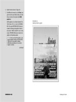
Lesson 4 Create Blends
ILLUSTRATOR 7-27
Create a clockwise
color blend
1. Open AI 7-10.ai, then save it as
Clockwise Blend.
2. Double-click the Blend Tool , click the
Spacing list arrow, click Specified Steps,
type 256 in the Spacing text box, then
click OK.
3. Click the top of the green line, then click the
top of the yellow line to create a blend, as
shown in Figure 39.
TIP The Blend Tool pointer turns black
when it is successfully positioned over an
anchor point.
4. Click the remaining five lines, ending with
the green line, to make five more blends, so
that your work resembles Figure 40.
5. Draw a circle over the blend that does not
exceed the perimeter of the blend.
6. Select all, click Object on the menu bar,
point to Clipping Mask, then click Make.
7. Click the Selection Tool , deselect, then
compare your image to Figure 41.
8. Save your work, then close the Clockwise
Blend document.
You created blends between six lines. You
specified the number of steps between each pair
of paths to be 256, which resulted in a visually
uninterrupted blend. You then masked the blend
with a circle.
FIGURE 39
A blend between two open paths
FIGURE 40
This color effect could not be reproduced with a gradient
FIGURE 41
The blended paths are masked by a circle
A smooth blend
between colors,
but not between
shapes
The use of 256 specified
steps improves the
appearance of the blend
ILLUSTRATOR 7-28
Working with Filters, Gradient Meshes, Envelopes, and Blends
Edit blends
1. Open AI 7-11.ai, then save it as Blends on
a Path.
2. Click the blended objects with the
Selection Tool .
3. Click Object on the menu bar, point to
Blend, then click Reverse Front to Back.
The stacking order of the blended objects is
reversed.
4. Click Object on the menu bar, point to
Blend, then click Reverse Spine.
The order of the objects on the path is
reversed.
5. Select all.
6. Click Object on the menu bar, point to
Blend, click Replace Spine, then deselect.
The curved path becomes the new spine for
the blend, as shown in Figure 42.
7. Save your work, then close the Blends on a
Path document.
You reversed the stacking order of a blend, then
reversed its spine. You then replaced the spine
with a curved path to create a 3-D effect.
FIGURE 42
Blends can be applied to paths
Lesson 4 Create Blends
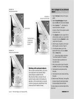
ILLUSTRATOR 7-29
Create color effects
with blends
1. Open AI 7-12.ai, then save it as Chrome.
2. Double-click the Blend Tool , then
change the number of specified steps to 256,
if necessary.
3. Switch to Outline mode, click the Selection
Tool , then select the five paths at the
bottom of the artboard.
Two of the paths are stroked with white and
cannot be seen in Preview mode.
4. Switch to Preview mode, click the Blend
Tool , then, starting from the bottom of
the artboard, create a blend between each
pair of paths, so that your work resembles
Figure 43.
5. Position the text over the blend.
6. Keeping the text selected, click Object on the
menu bar, point to Compound Path, then
click Make.
7. Select all, click Object on the menu bar,
point to Clipping Mask, then click Make.
8. Deselect all, click Select on the menu bar,
point to Object, then click Clipping Masks.
9. Apply a 2-point black stroke to the mask.
10.Deselect, save your work, compare your
screen to Figure 44, then close the Chrome
document.
You created blends between five paths, then
masked the blend with text.
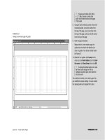
FIGURE 43
A simple blend between open paths
FIGURE 44
Chrome letters created with a blend and a mask
CHAPTER SUMMARY
This chapter shows how fun Illustrator
can be. You can get carried away with
applying filters, envelopes and blends to
your objects. These features, along with
the Gradient Mesh feature, are all made
easy because they do the work for you.
You can distort objects and blend colors
among objects using filters. You can cre-
ate realistic illustrations when you use
create gradient meshes. Gradient meshes
break your illustration into patches to
which you can add color that blends in
any direction you choose by manipulating
the mesh points and the mesh lines.
Finally, you can blend two or more
objects to create a series of objects
between them. Experimenting with the
features in this chapter will show you just
how powerful Illustrator can be.
What You Have Learned
• How to distort shapes using the Free
Distort filter
• How to blend colors using the Colors
filter
• How to saturate and desaturate an
illustration
• How to use the Pucker & Bloat and
Twist filters
• How to create a gradient mesh
• How to manipulate a gradient mesh
• How to create an envelope distortion
with a top object
• How to create an envelope distortion
with a mesh
• How to create an envelope distortion
with a warp effect
• Create a blend between shapes
• Create a clockwise color blend
• Edit blends
• Create color effects with blends
Key Terms
Mesh object A single, multicolored
object in which colors can flow in differ-
ent directions, and colors transition grad-
ually from point to point.
Mesh lines Lines that crisscross a
mesh object, joined at their intersections
by mesh points.
Mesh points Diamond-shaped points
that work just like anchor points, with
the added functionality of being able to be
assigned a color.
Mesh patch The area between four
mesh points.
Envelopes Objects that are used to
distort other selected objects; the dis-
torted objects take on the shape of the
envelope object.
Blend A series of intermediate objects
and colors between two or more selected
objects.
ILLUSTRATOR 7-30
Working with Filters, Gradient Meshes, Envelopes, and Blends