Adobe Photoshop CS2 Photographers’ Guide phần 6 potx
Bạn đang xem bản rút gọn của tài liệu. Xem và tải ngay bản đầy đủ của tài liệu tại đây (2.68 MB, 39 trang )
Extracting the Kitten
Photoshop includes several tools specifically designed to help you isolate parts of
images from their backgrounds. These include the Background Eraser and the
Extract command. The Background Eraser is the simpler of the two: It’s nothing
more than an eraser with a circular cursor, similar to that used by the Magnetic
Lasso discussed earlier in this chapter. Set a Tolerance level in the Option bar,
choose a size for the eraser, and use the Background Eraser to remove pixels that
don’t closely match the pixels in your main subject. This tool is useful for objects
that have a fairly hard edge and a distinct background and, in such situations,
offers little advantage over selection tools, such as the Magic Wand.
The Extract command, moved from the Image menu to the Filter menu in
Photoshop 7 and later versions, provides much more sophisticated removal of sur-
rounding areas. You can carefully paint a mask around the edges of your object,
adjust the borders, and preview your result before extracting the object. Extract
works very well with wispy or hairy objects. Follow these steps.
1. The Extract command works best with images that are sharp, so the first
thing to do is sharpen the kitten image using Filter > Sharpen > Unsharp
Mask. Use a setting of 100 percent or more to make every hair on the kitten’s
body stand out.
Chapter 5 ■ Compositing in Photoshop CS 175
Figure 5.42 Crouching
kitten, hidden background.
2. Activate the Extract command by choosing Filter > Extract, or by pressing
Alt/Option + Ctrl/Command + X. The dialog box shown in Figure 5.43 will
appear.
Adobe Photoshop CS2: Photographers’ Guide176
Figure 5.43 The Extract
command lets you remove
objects from their
backgrounds.
3. Zoom in on the portion of the image you want to extract. In this case, focus
on the upper edge of the kitten. Zooming within the Extract dialog box is
done in exactly the same way as within Photoshop. Use the Zoom tool (avail-
able from the dialog box’s Tool Palette at the left edge) or simply press
Ctrl/Command + space to zoom in or Alt/Option + space to zoom out.
4. Click the edge highlighter/marker tool at the top of the Tool Palette. Choose
a brush size of 20 from the Tool Options area on the right side of the dialog
box.
5. Paint the edges of the kitten with the marker. Use the Eraser tool to remove
markings you may have applied by mistake, or press Ctrl/Command + Z to
undo any highlighting you’ve drawn since you last clicked the mouse. The
Hand tool can be used to slide the image area within the Preview window.
6. When you’ve finished outlining the kitten, click the Paint Bucket tool and fill
the area you want to preserve.
7. Click the Preview button to see what the kitten will look like when extracted,
as shown in Figure 5.44.
8. If necessary, use the Cleanup tool (press C to activate it) to subtract opacity
from any areas you may have erased too enthusiastically. This will return some
of the texture of the kitten’s fur along the edge. Hold down the Alt/Option
key while using the Cleanup tool to make an area more opaque.
9. Use the Edge Touchup tool (press T to activate it) to sharpen edges.
10. Click on the OK button when satisfied to apply the extraction to the kitten.
Kitten on a Desktop
Load the Chinese Desk image, shown in Figure 5.45, from the website as we begin
to give the kitten a new home. Follow these steps to deposit her on the shiny black
surface.
1. Select the kitten from the original image, and paste her down into the Chinese
Desk photo. Use Edit > Transform > Scale to adjust her size to one that’s real-
istic for the desktop.
2. Use Image > Adjustments > Brightness/Contrast to boost the contrast of the
kitten to match the harder lighting of the desk surface.
3. Press Q to enter Quick Mask mode, and using a fairly large soft-edged brush,
paint the undersides of the kitten’s feet, body, and tail. Press Q again to exit
Quick Mask mode and use the Brightness/Contrast controls again to darken
these under-surfaces.
Chapter 5 ■ Compositing in Photoshop CS 177
Figure 5.44 Preview your
extraction before applying the
effect.
4. Press Ctrl/Command + D to deselect everything in the image, then use Quick
Mask mode to paint a selection that encompasses the kitten’s eyes. Exit Quick
Mask mode and use Brightness/Contrast to lighten the eyes dramatically and
give them much more contrast. Your image will now look like the one shown
in Figure 5.46.
Adobe Photoshop CS2: Photographers’ Guide178
Figure 5.45 This Chinese
desk will make an interesting
background for our crouching
tiger kitten.
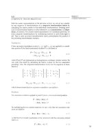
Figure 5.46 Darken the
underside of the kitten, and
lighten her eyes.
Creating a Reflection
Notice that parts of the desk are reflected in the shiny black surface. The kitten
needs a realistic reflection of her own. Here’s how to do it.
1. Choose Layer > Duplicate to duplicate the kitten layer.
2. Select Edit > Transform > Flip Vertical to produce a mirror image of the kitten.
3. Use Edit > Transform > Rotate to rotate the mirror image counterclockwise
so it will appear at the side of the kitten, rather than in front of it.
4. Reduce the opacity of the reflection to about 30 percent, using the slider in
the Layers Palette.
5. Here’s the sneaky part: adjust the way the reflection merges with the shiny desk-
top by selecting Difference as the merging mode in the Layers Palette. This will
ensure that darker parts of the reflection merge with the desktop, while letting
the lighter parts show through. This produces a more realistic reflection than
one in which the reflection layer completely overlays the desktop layer.
6. You can optionally apply some Gaussian Blur to the reflection to soften it, or
leave the reflection sharp to give the desktop a shinier appearance. I didn’t use
Blur in the image shown in Figure 5.47, but you might want to.
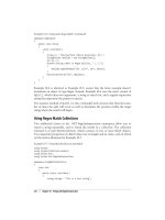
7. Create a new transparent layer, and, using a two-pixel white brush, paint in
some whiskers on the right side of the kitten. The whiskers typically are too
wispy to extract well, so I usually allow them to be erased and then replace
them later.
8. Set the opacity of the whiskers layer to about 60% and apply Gaussian Blur
to them until they match the kitten’s other whiskers fairly well.
Chapter 5 ■ Compositing in Photoshop CS 179
Figure 5.47 Add a reflection
and some whiskers.
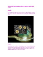
More than One Way to Skin a Cat
You can colorize the kitten (or any other object you care to) in a realistic way using
the following trick. I wanted to make this cat a little more tiger-like, so I enhanced
its coloring a little with some bright orange-yellow. That’s not as simple as you
might think. If you color the cat using the Hue/Saturation controls, you’ll apply
color to all of it, losing some of the subtle color in its eyes. Follow these steps,
instead:
1. Duplicate the kitten’s layer using Layer > Duplicate.
2. Choose Image > Adjustments > Hue/Saturation, and move the Hue and
Saturation controls until you get the color you want. Click on OK to apply
the modification to the duplicate of the kitten layer.
3. Choose the Overlay Merging mode in the Layers Palette to merge the col-
orized layer with the original kitten in the layer underneath. This technique
will let other colors show through, smoothly merging the new color with the
original image.
4. Use the Brightness/Contrast controls on the colorized layer to get the color
exactly the way you like. Usually, it’s best to reduce the contrast a little and
add some brightness, as I did for the final image, shown in Figure 5.48.
Adobe Photoshop CS2: Photographers’ Guide180
Figure 5.48 A slick colorizing trick gives the kitten a tiger’s pelt.
Compositing Possibilities
Here’s a quick summary of some of the other things you can do with compositing.
You’ll want to try your hand at all of these as you become a Photoshop master.
■ Remove large objects. You can’t retouch large objects out of a photo, but you
can replace an unsightly barn, brother-in-law, or auto junkyard in the back-
ground with something else, such as trees, a mountain, or a lake.
■ Relocate things in the photo. Compositing gives you the opportunity to cor-
rect faulty compositions, change the center of interest in a photo, or make
something else a little easier to see.
■ Replace components of the photograph. That photo of your home looks
great, but you no longer own that car parked out front. Drop in a picture of
your new jalopy using Photoshop CS’s compositing techniques.
■ Adding new objects to a photo. Could your beach scene use some palm
trees? Would you like to see J-Lo standing in the middle of your class reunion
photo? Do you hope to work for a tabloid newspaper some day? Experiment
with adding objects using compositing.
■ Squeeze things together, or stretch them apart. If you have a picture that
is too wide for your intended use, you can often take the left and right halves,
overlap them, disguise the seam, and end up with a narrower photo that fits,
but doesn’t look distorted.
Combining Compositing and Retouching
Do you remember those photos taken at your wedding reception, in which your
new brother-in-law managed to intrude on every photo? Do you have a great-
looking group shot of everybody in your department at work—including Elmo,
who was fired last month? Wouldn’t it be great if you could just paint the offend-
ers out of a photograph with one stroke? Photoshop takes more than one stroke,
but it can do the job for you. Try this project to see how easy it is. Lacking a nasty
in-law, we’re going to clean up a vacation photo by deleting a poorly posed sub-
ject, shown at left in Figure 5.49. Our weapons of choice for this exercise are the
Clone Stamp retouching tool and a simple compositing technique. You can fol-
low along using the kids file on the website.
The obvious solution, of course, would be to crop the kid out of the picture.
However, that would snip out the interesting house on the hill in the background.
Another remedy would be to copy the portion of the fence at the right of the
picture and paste it down over the unwanted subject. Unfortunately, that stretch
of fence and its background is very dark, and duplicating it would provide an
Chapter 5 ■ Compositing in Photoshop CS 181
unattractive dark area at the lower-right corner of the picture. Cloning lets us
preserve the background area that’s already there, deleting only the boy. Here’s
how to do it.
1. Press S to choose the Clone Stamp tool, and select a medium-sized (say, 35-
pixel) soft-edged brush.
2. Hold down the Alt/Option key and click in the foliage between the fence rail-
ings to select that area as the source for cloning.
3. Carefully clone over the boy, a little bit at a time. Resample the foliage
by Alt/Option + clicking frequently. If your clone “source” (repre-
sented by a cross-hair that appears briefly to one side of your brush
icon each time you click) moves into an area that has already been
cloned, you’ll get a repeating fish-scale effect like the one shown in
Figure 5.50.
4. Continue cloning to paint over the boy completely. Don’t worry about
the fence railing at this time; we’ll fix that later. The important thing
is to reproduce a realistic background as it would appear behind the
subject if he weren’t there. After a while, your image should begin to
look like the examples shown in Figure 5.51.
5. Copy a horizontal section of the railing from the far-left side of the
fence, using the Rectangular marquee tool. You should be able to use
this tool to select only the fence railing, and none of the background
area.
Adobe Photoshop CS2: Photographers’ Guide182
Figure 5.49 We can remove
the kid at left painlessly.
Figure 5.50 Avoid the fish-scale
look that comes from cloning from
an area that already has been cloned.
6. Paste the horizontal section into the image over a portion of the rail that has
been obscured by cloning.
7. Repeat steps 5 and 6 until all the horizontal railings have been “patched.”
Then do the same for the vertical railings. Merge all the transparent layers
containing the railings (make all the layers except those containing railings
visible, and with the top rail layer selected, press Shift + Ctrl/Command + E
[Merge Visible]). You’ll end up with an image that looks like Figure 5.52. (I’ve
left the selection boundaries visible so you can see the duplicated portion of
the fence.)
Chapter 5 ■ Compositing in Photoshop CS 183
Figure 5.51 The kid is
gradually cloned away.
Figure 5.52 Add railings
from the other side of the
picture.
8. The remaining boy is still a bit too much taller than the girls in the photo, so
you can copy him, paste his image into the picture, and move him down a
bit. Use the Clone Stamp tool, as necessary, to blend in the background.
9. Finally, use the Burn toning tool to darken the background and the girls at
left. The finished picture looks like Figure 5.53.
Adobe Photoshop CS2: Photographers’ Guide184
Next Up
Color correction is another important image editing technique you’ll want to mas-
ter as you learn to enhance your photos. In the next chapter, I’m going to show
you at least four ways to improve colors of any image, or modify them to create
some special effects.
Figure 5.53 The finished image looks like this.
Color is cool. Color is hot. Photographers know that color is a powerful tool that
can grab the eye, lead our attention to specific areas of an image, and, through
some unknown process, generate feelings that run the emotional color gamut from
ardor to anger.
Conversely, bad color can ruin an image. It’s a fact of life that a well-composed
image that might look sensational in black and white can be utterly ruined sim-
ply by presenting it in color with inappropriate hues or saturation. Bad color can
override every other aspect of a photograph, turning wheat into chaff. But what,
exactly, is bad color?
The most interesting thing about color is that the concept of good and bad can
vary by the image, the photographer’s intent, and the purpose of the finished pho-
tograph. The weird colors of a cross-processed image are very bad if they show up
in your vacation pictures, but wonderfully evocative in a fashion shoot. A photo
that has a vivid red cast may look terrible as a straight portrait, but interesting
when part of a glamour shot taken by the glowing embers of a fireplace. A picture
of a human with even the tiniest bit of a blue tinge looks ghastly, but might add
the desired degree of chill to a snowy winter scene.
Strictly speaking, you don’t have to understand how color works to use it to make
corrections or generate striking effects. It’s entirely possible to use trial-and-error
experimentation to arrive at the results you want. However, just because you don’t
need an electrical engineering degree to operate a toaster, it’s good to know a lit-
tle something about electricity before you go poking around inside with a fork.
6
Correcting Your Colors
This chapter provides a gentle introduction to the color theories that photogra-
phers work with everyday, and which become even more useful when you begin
working with Photoshop. You’ll learn more about the most frequently used color
models and the differences between the way color is viewed in the real world, cap-
tured by a film or digital camera, displayed on your monitor, and output by your
printer. I’ll spare you the hypertechnical details of working with color curves. If
you need to fine-tune color that precisely, you need a prepress guide like Dan
Margulis’ Professional Photoshop.
All the color correction tools in this chapter will be easy to use. Even so, you’ll be
able to work with them effectively because, before we ever touch a slider, I’m going
to give you enough background in color that correction will be almost second
nature to you.
Wonderful World of Color
In a sense, color is an optical illusion. Human perception of color is a strange and
wonderful thing, created in our brains from the variation of the wavelengths of
light that reach our eyes. If you remained awake during high-school science class,
you’ll recall that the retina of the eye contains rod cells (which are used for detail
and black-and-white vision when there is not much light) and three types of cone
cells, which respond to a different wavelength of light, all in the 400 nanometer
(violet) to 700 nanometer (red) range of what we call the color spectrum.
All the colors we could see (if our eyes were constructed that way) would reside in
that continuous color spectrum, like the one shown in Figure 6.1. However, we
can’t directly sense each of those individual colors. Instead, each of the three kinds
of cone cells in our eyes “see” a different set of frequencies, which happen to cor-
respond to what we call red, green, and blue (RGB). Our brains process this RGB
information and translate it into a distinct color that we perceive.
Adobe Photoshop CS2: Photographers’ Guide186
Figure 6.1 Our eyes don’t
perceive the full spectrum of
color, but capture hues
through three different kinds
of cone cells in the retina.
Color films use a minimum of three different layers of photosensitive emulsion,
each sensitive to red, green, and blue light. Digital cameras have three sets of color
sensors, and scanners use three light sources, three arrays of sensors, or filters to
capture red, green, and blue information. Finally, when digital information is seen
on computer monitors, the same three colors (in the form of LCD pixels or CRT
phosphors) complete the circle by displaying the color information for our eyes
to view again.
Digital cameras work something like color film, responding to red, green, and blue
light. However, except for some alternative technologies, such as the Foveon sen-
sor currently used only in the Sigma SD9 and SD10 digital SLR cameras, and the
seldom seen Polaroid X530 point-and-shoot model, camera sensors do not have
separate red/green/blue layers. Instead, each pixel in a digital camera image is sen-
sitive to only one color, and interpolation is used to calculate the correct color for
a particular photosite if something other than the color it’s been assigned falls on
that pixel.
The various capture and display processes are significant for an important reason.
None of the systems used to grab or view color respond to red, green, and blue
light in exactly the same way. Some are particularly sensitive to green light; indeed,
digital cameras are designed with twice as many green-sensitive sensors than red
or blue. Most systems don’t respond to all the colors in a perfectly linear way,
either, so that a hue that is twice as intense may register slightly less or a bit more
intense.
And it gets worse: The models used to represent those colors in the computer also
treat colors in different ways. That’s why an image you see in real life may not look
exactly the same in a color slide, a color print, a scanned image, on your screen,
or when reproduced by a color printer or printing press. Simply converting an
image from RGB to CMYK (more on that later) can change the colors signifi-
cantly. The concept of the range and type of colors that can be captured, manip-
ulated, and reproduced by a given device or system—its color gamut—is an
important one for photographers working in Photoshop.
Color Models
Artificial color systems, which include computer scanners, monitors, printers, and
other peripherals, attempt to reproduce, or model, the colors that we see, using
various sets of components of color. If the model is a good one, all the colors we
are capable of detecting are defined by the parameters of the model. The colors
within the definition of each model are termed its color space. Because nearly all
color spaces use three different parameters such as colors (red, green, and blue, for
example) or qualities (such as hue, saturation, and brightness), we can plot them
as x, y, and z coordinates to produce a three-dimensional shape that represents the
color gamut of the model.
The international standard for specifying color was defined in 1931 by the
Commission Internationale L’Eclairage (CIE); it is a scientific color model that
can be used to define all the colors that humans can see. However, computer color
systems are based on one of three or four other color models, which are more prac-
tical because they are derived from the actual hardware systems used to reproduce
those colors.
Chapter 6 ■ Correcting Your Colors 187
None of these systems can generate all the colors in the full range of human per-
ception, but they are the models with which we must work. There have been some
efforts to define new color working spaces, such as sRGB, but so far nothing has
appeared that will completely take over the photography and computer graphics
industries. Indeed, learning to work with Photoshop’s sRGB setting was one of
the most popular topics among puzzled users when Photoshop 6 was introduced.
The topic has been renewed with the popularity of digital cameras, because some
of them, like my own Nikon D70, can use several slight variations of color mod-
els, including sRGB and what is called Adobe RGB. Your best bet is to learn some-
thing about all color working spaces, since image editors like Photoshop support
several different color models.
Of the three most common models, the ones based on the hue-lightness-satura-
tion (HLS) and hue-saturation-value (HSV) of colors are the most natural for us
to visualize, because they deal with a continuous range of colors that may vary in
brightness or richness. You use this type of model when you adjust colors with the
Hue/Saturation dialog boxes.
Two other models, called additive color and subtractive color, are easier for com-
puters to handle, because the individual components are nothing more than three
basic colors of light. Throughout this book, I’ve referred to these models as RGB
and CMY (or CMYK, for cyan, magenta, yellow, and black).
Additive color is commonly used for image capture by cameras and scanners, and
in computer display monitors, while subtractive color is used for output devices
such as printers. Since you need to understand how color works with these periph-
erals, I’ll explain the additive and subtractive models first.
Additive Color
Computer monitors produce color by aiming three electronic guns
at sets of red, green, and blue phosphors (compounds which give
off photons when struck by beams of electrons), coated on the
screen of your display. LCD and LED monitors use sets of red,
green, and blue pixels to represent each picture element of an image
that are switched on or off, as required. If none of the colors are dis-
played, we see a black pixel. If all three glow in equal proportions,
we see a neutral color—gray or white, depending on the intensity.
Such a color system uses the additive color model—so called
because the colors are added together, as you can see in Figure 6.2.
A huge selection of colors can be produced by varying the combi-
nations of light. In addition to pure red, green, and blue, we can
also produce cyan (green and blue together), magenta (red and
blue), yellow (red and green), and all the colors in between. As with
Adobe Photoshop CS2: Photographers’ Guide188
Figure 6.2 The additive color system uses
beams of light in red, green, and blue hues.
grayscale data, the number of bits used to store color information determines the
number of different tones that can be reproduced.
Figure 6.2 shows one way of thinking about additive color, in a two-dimensional
color space. The largest circles represent beams of light in red, green, and blue.
Where the beams overlap, they produce other colors. For example, red and green
combine to produce yellow. Red and blue add up to magenta, and green and blue
produce cyan. The center portion, in which all three colors overlap, is white. If
the idea that overlapping produces no color, rather than some combined color
seems confusing, remember that the illumination is being added together, and
combining all three of the component colors of light produces a neutral white
with equal amounts of each.
However, if you look at the figure, you’ll see that it shows overlap-
ping circles that are each more or less the same intensity of a single
color (allowing some artistic license for the 3D “shading” effect
added to keep the individual circles distinct). For that reason, this
two-dimensional model doesn’t account for the lightness or dark-
ness of a color—the amount of white or black. That added dimen-
sion is dealt with by, literally, adding a dimension, as you can see in
the mock 3D model shown in Figure 6.3.
The figure shows red, green, and blue colors positioned at opposite
corners of the cube, with their complementary colors arranged
between them. White and black are located opposite one another,
as well. Any shade that can be produced by adding red, green, and
blue together can be represented by a position within the cube.
No widely used display device available today produces pure red,
green, or blue light. Only lasers, which output at one single fre-
quency of light, generate absolutely pure colors, and they aren’t used
for display devices. We see images through the glow of phosphors,
LEDs, or LCD pixels, and the ability of these to generate absolutely
pure colors is limited. Color representations on a display differ from brand to
brand and even from one display to another within the same brand.
Moreover, the characteristics of a given display can change as the monitor ages
and the color-producing elements wear out. Some phosphors, particularly blue
ones, change in intensity as they age, at a different rate than other phosphors. So,
identical signals rarely produce identical images on displays, regardless of how
closely the devices are matched in type, age, and other factors.
In practice, most displays show far fewer colors than the total of which they are
theoretically capable. Actually, the number of different colors a display can show
at one time is limited to the number of individual pixels. At 1024 × 768 resolu-
tion, there are only 786,432 different pixels. Even if each one were a different
Chapter 6 ■ Correcting Your Colors 189
Figure 6.3 The RGB color space can be
better represented by a three-dimensional
cube, simplified to corners and edges in this
illustration.
color, you’d view, at most, only around three-quarters of a million colors at once.
The reason your digital camera, scanner, display, and Photoshop itself need to be
24-bit compatible is so the right 786,432 pixels (or whichever number is actually
required) can be selected from the available colors that can be reproduced by a
particular color model’s gamut. In practice, both scanners and digital cameras cap-
ture more than 24 bits worth of color, to allow for the inevitable information lost
in translating a full-spectrum image to digital form. To understand why, you need
to understand a concept called bit depth.
As you know from working with Photoshop, the number of theoretical colors that
can be represented is measured using that bit depth yardstick. For example, “4-
bit” color can represent the total number of colors possible using four bits of
binary information (0000 to 1111), or 16 colors. Similarly, 8-bit color can repre-
sent 256 different colors or grayscale tones, while “high color” 15- or 16-bit dis-
plays can represent 32,767 or 65,535 colors. You’ll sometimes encounter high
color images when you’re displaying at very high resolutions using video cards
which don’t have enough memory for 24-bit color at that resolution.
For example, perhaps you own a 21-inch or larger monitor capable of displaying
images at 2048 × 1536 pixels of resolution, and you are working with an older
video card that can display only 65,535 colors at that resolution. This example is
Adobe Photoshop CS2: Photographers’ Guide190
WHEN ARE 32 BITS ACTUALLY 24 BITS? AND WHEN IS 32 MORE
THAN 32?
In the past, when you used Photoshop with so-called 32-bit color images, you were
actually working with ordinary 24-bit images, plus an extra 8 bits used to store
grayscale alpha channel information. The image itself was usually a normal 24-bit
image. In this case, the extra 8 bits store your selections, layer masks, and so forth.
On the other hand, in Photoshop CS2 terminology, “16-bit color” usually doesn’t
refer to those “high-color,” 65,535-hue images, either. Within Photoshop “16-bit
color” means 16 bits per color channel, so the image is actually a 48-bit (16 bits × 3
channels)representation. Photoshop 2.0 added an extra dimension—that of high-
dynamic range color. HDR color also uses 16-bits of information to store informa-
tion about each channel. However, there is a difference, one that can be confusing
until you wrap your mind around it. Those 16 bits of information are stored as
floating decimal point numbers, which are inherently a lot more accurate. If it’s been
as long for you as it has for me since math class, the easiest way to understand the
difference is to think of expressing the idea of one-third only with integers (33 per-
cent) or with a floating point number like 33.3333333333333333 percent. Less
information is lost to rounding errors, etc. HDR uses 32-point floating point num-
bers to help preserve the dynamic range of your color images. You’ll learn more
about this later in the chapter.
a bit farfetched, because most video cards today have enough memory to display
at least 16.8 million colors at whatever their maximum resolution is. You will,
however, sometimes encounter a card that must step down to a lower color depth
to display its absolute top resolution.
For most applications, 16-bit color is as good as 24-bit color. Image editing with
Photoshop CS2 is not one of them. It actually has robust high dynamic range
(HDR) capabilities that extend even beyond 24 bit color. So, 24-bit color is, at
best, the minimum you should work with. Happily, the standard today is that
video cards generally have 64MB or more of memory, and are fully capable of dis-
playing 24-bit full color at any supported resolution, and 16.8 million different
hues. Scanners and some high-end digital cameras can even capture 36 bits or 48
bits of color, for a staggering billions and billions of hues. The extra colors are use-
ful to provide detail in the darkest areas of an image, especially when you consider
that many bits of information are lost during the conversion from an analog sig-
nal (the captured light) to digital (the image file stored on your computer).
Subtractive Color
There is a second way of producing color that is familiar to computer users—one
that is put to work whenever we output our Photoshop images as hard copies using
a color printer. This kind of color also has a color model that represents a partic-
ular color gamut. The reason a different kind of color model is necessary is sim-
ple: When we represent colors in hardcopy form, the light source we view by
comes not from the image itself, as it does with a computer display. Instead, hard
copies are viewed by light that strikes the paper or other substrate and then is fil-
tered by the image on the paper, then reflected back to our eyes.
This light starts out with (more or less) equal quantities of red,
green, and blue light and looks white to our eyes. The pigments the
light passes through before bouncing off the substrate absorb part
of this light, subtracting it from the spectrum. The components of
light that remain reach our eyes and are interpreted as color. Because
various parts of the illumination are subtracted from white to pro-
duce color, this color model is known as the subtractive system.
The three primary subtractive colors are cyan, magenta, and yellow,
and the model is sometimes known as the CMY model. Usually,
however, black is included in the mix, for reasons that will become
clear shortly. When black is added, this color system becomes the
CMYK model (black is represented by its terminal character, k,
rather than b to avoid confusion with the additive primary blue).
Figure 6.4 shows the subtractive color model in a fanciful repre-
sentation, retaining the color filter motif I started out with in
Chapter 6 ■ Correcting Your Colors 191
Figure 6.4 The subtractive color system
uses cyan, magenta, and yellow colors.
describing the additive color system. (You couldn’t overlap filters to produce the
colors shown, although you could print with inks to create them.)
In subtractive output devices such as color printers or printing presses, cyan,
magenta, yellow, and, usually, black pigments (for detail) are used to represent a
gamut of colors. It’s obvious why additive colors won’t work for hard copies: It is
possible to produce red, green, and blue pigments, of course, and we could print
red, green, and blue colors that way (that’s exactly what is done for spot color).
However, there would be no way to produce any of the other colors with the addi-
tive primaries. Red pigment reflects only red light; green pigment reflects only
green. When they overlap, the red pigment absorbs the green, and the green
absorbs the red, so no light is reflected and we see black.
Cyan pigment, on the other hand, absorbs only red light (well, it is supposed to).
It reflects both blue and green (theoretically), producing the blue-green shade we
see as cyan. Yellow pigment absorbs only blue light, reflecting red and green, while
magenta pigment absorbs only green, reflecting red and blue. When we overlap
two of the subtractive primaries, some of at least one color still reflects. Magenta
(red-blue) and yellow (red-green) together produce red, because the magenta pig-
ment absorbs green and the yellow pigment absorbs blue. Their common color,
red, is the only one remaining. Of course, each of the subtractive primaries can
be present in various intensities or percentages, from 0 to 100%. The remainder
is represented by white, which reflects all colors in equal amounts.
So, in our example above, if the magenta pigment was only 50% present and the
yellow represented at 100%, only half of the green would be absorbed, while
100% of the blue would be soaked up. Our red would appear to be an interme-
diate color, orange. By varying the percentages of the subtractive primaries, we
can produce a full range of colors.
Well, theoretically we could. You’ll recall that RGB displays aren’t perfect because
the colors aren’t pure. So, too, it is impossible to design pigments that reflect
absolutely pure colors. Equal amounts of cyan, magenta, and yellow pigment
should produce black. More often, what you’ll get is a muddy brown. When daily
newspapers first began their changeover to color printing in the 1970s, many of
them used this three-color system, with mixed results.
However, better results can be obtained by adding black as a fourth color. Black
can fill in areas that are supposed to be black and add detail to other areas of an
image. While the fourth color does complicate the process a bit, the actual cost in
applications like offset printing is minimal. Black ink is used to print text anyway,
so there is no additional press run for black. Moreover, black ink is cheaper than
critical process color inks, so it’s possible to save money by using black instead of
laying on three subtractive primaries extra thick. A typical image separated into
its component colors for printing is shown in Figure 6.5.
Adobe Photoshop CS2: Photographers’ Guide192
The output systems you use to print hard copies of color images use the subtrac-
tive color system in one way or another. Most of them are unable to print vary-
ing percentages of each of the primary colors. Inkjet printers, color laser printers,
and thermal wax transfer printers are examples of these. All these systems must
simulate other colors by dithering, which is similar to the halftoning system dis-
cussed earlier. A few printers can vary the amount of pigment laid down over a
broader range. Thermal dye sublimation printers are an example of
this type. These printers can print a full range of tones, up to the
16.8 million colors possible with 24-bit systems.
The subtractive color system can also be represented in three dimen-
sions, as I’ve done in Figure 6.6. In this illustration, the positions of
the red, green, and blue colors have been replaced by cyan, magenta,
and yellow, and the other hues rearranged accordingly. In fact, if you
mentally rotate and reverse this figure, you’ll see that it is otherwise
identical to the one in Figure 6.3; RGB and CMYK are in this sense
two sides of the same coin. However, don’t make the mistake of
thinking their color spaces are identical. There are colors that can
be displayed in RGB that can’t be printed using CMYK.
When you view color images on your display during image editing
with Photoshop, the colors in the image file are always converted to
additive (RGB) colors for display—regardless of the color model
Chapter 6 ■ Correcting Your Colors 193
Figure 6.5 Full-color images
are separated into cyan,
magenta, yellow, and black
components for printing.
Figure 6.6 The subtractive color model can
also be represented by a 3D cube.
Figure 6.7 The
hue/saturation/brightness color
model starts with a color circle
or hexagon like this one.
used to represent the actual image. However—and this is important—the color
model used for the actual file remains the same, unless you change modes and
then save the file. In truth, Photoshop uses another color model, called Lab (dis-
cussed below), as an intermediate when converting from one color to another.
For example, if you load a file that has been saved using the CMYK color model,
a program like Photoshop will let you work on it in CMYK mode, even though
the colors must be converted to RGB for viewing. In general, CMYK colors will
seem less saturated and duller than RGB colors. That’s because RGB colors can
be made brighter by pumping more light through the device you’re using to view
them. CMYK colors are limited by the brightness of the substrate (a “whiter” paper
will reflect more light and brighter colors) and the amount of ink used.
Within Photoshop, you don’t actually lose any colors unless you physically con-
vert the file from one mode to the other. If you do convert from CMYK to RGB
mode and back again, because CMYK can represent some colors that are outside
the RGB gamut—and vice versa—you will lose some hues each time. Stick with
CMYK if that’s the mode your file was created in, especially if you will be out-
putting to a printer or color separation system that expects to work with CMYK
colors. That way, you’ll avoid creating RGB colors which cannot be reproduced
by the CMYK output system. Photoshop will handle your file in Lab mode, and
protect your colors.
Lab color was developed by the CIE as a device-independent international stan-
dard. Lab consists of three components, a luminance channel, plus a* and b* chan-
nels that represent green to magenta and blue to yellow, respectively. Because
CIELab can represent all the colors found in both RGB and CMYK, it serves as
a perfect intermediate format for Photoshop. There are some highly technical
operations that can be carried out in Lab mode. In addition, Lab colors more
closely reflect how humans perceive color, so if there is a difference in color in
CIELab mode, humans will probably perceive a difference, too. That’s not always
the case with RGB and CMYK modes.
Other Color Models
The hue-saturation-brightness color model, also known as HSB or HLS (for hue-
lightness-saturation), is a convenient way to manage color for some operations.
For example, if you want to adjust the saturation of a color without modifying its
hue or brightness, HSB mode (using Image > Adjustments > Hue/Saturation) is
the way to go. In this model, individual colors, called hues, are represented as they
are in a rainbow, as a continuous spectrum, arranged in a hexagon like that shown
in Figure 6.7. The full color space is represented as a double hexcone that extends
upwards and downwards from the hexagon, as shown in Figure 6.8. The top of
the axis drawn through the center of the cones represents pure white, while the
Adobe Photoshop CS2: Photographers’ Guide194
bottom point represents black. Moving higher in the cone produces lighter
colors; moving lower in the bottom cone produces darker colors. Saturation
is represented by movement in a third direction, outward from the center
axis. The center represents a desaturated color and the outer edges represent
fully saturated hues.
All colors can be represented by three parameters in this model. The hue is
the particular position of a color in the color wheel. Hues are often repre-
sented by angles, beginning with red at 0° and progressing around in a coun-
terclockwise direction to magenta at 60°, blue at 120°, and so forth. The
saturation of the color is the degree to which that color is diluted with white.
A hue with a great deal of white is muted; a red becomes a pink, for exam-
ple. A hue with very little or no white is vivid and saturated. Brightness can
be thought of as the degree to which a color is diluted with black. Add black
to our desaturated red (pink), and you’ll get a very dark pink. Various com-
binations of hue, saturation, and brightness can be used to produce just
about any color we can see. Individual hues can be found along the edges
of the hexagon. Moving from that edge toward the center within the same
plane indicates a color that is less saturated. The center of the hexagon rep-
resents zero saturation. The axis extending through the center of the hex-
cones represents lightness and darkness, with white at the top and black at
the bottom of the line.
Capturing Color Images
Today we have several options for capturing images for
manipulation in Photoshop. Color scanners have
been around the longest, for around 50 years, in fact.
The first ones I saw early in my career cost more than
a million dollars when you included the computer
equipment needed to drive them, and they were
intended only for professional graphics applications at
service bureaus and large publications. Today, color
scanners, like the one shown in Figure 6.9, can cost less
than $100.
Color scanners are nothing more than a system for
capturing the proper amount of each of the primary
colors of light in a given image. So, these scanners use
three different light sources—one each of red, green,
and blue—to scan a color image. To do so, some older
scanners actually made three passes over the image—
once for each color. More recent scanners use multiple
Chapter 6 ■ Correcting Your Colors 195
Figure 6.8 The full color space is
represented by two hexagonal
cones. Moving from the center
outward produces more saturated
colors, while moving up or down
the axis of the cones darkens or
lightens the color.
Figure 6.9 Modern color scanners can cost $100 or less.
light sources, or “rotate” their illumination, using red/green/blue light in succes-
sion to capture an image in a single pass.
The amount of light reflected by the artwork for each color varies according to
the color of the pigments in the original. Cyan pigment, for example, absorbs red
light and reflects blue and green. So, when a cyan area is illuminated by the red
fluorescent light in a scanner, relatively little light is reflected. Most of the light
produced by the blue and green fluorescents is reflected. Your scanner software
records that area of the original as cyan. A similar process captures the other col-
ors in your subject during the scan. Even if you don’t use a scanner yourself, you
may work with scanned images that are captured by your photofinisher when con-
verting your color slides or prints to digital form for distribution online or as a
PhotoCD or Picture CD.
Digital cameras cut out the middle step by creating color images directly. Where
scanners use a linear array that grabs an image one line at a time, digital cameras
use a two-dimensional array that grabs a complete bitmap in one instant. Today,
digital cameras with 3.3 to 6 megapixels (or more) of resolution can capture images
that are virtually indistinguishable from those grabbed on film when reproduced
or enlarged to 8 × 10 inches or less.
You’ll find more information about color scanners in my book Mastering Digital
Scanning with Slides, Film, and Transparencies (ISBN: 1-59200-141-6) and lots
more nuts-and-bolts on digital cameras in Mastering Digital Photography (ISBN:
1-59200-114-9). If you want to learn how digital cameras capture color, check
out Mastering Digital Photography or Mastering Digital SLR Photography. All three
books are available from Course Technology, and you can find more information
about them at my website, www.dbusch.com.
Color Calibration and Gamma Curves
Conventional film is well-known for having color reproduction characteristics that
vary over a considerable range. Some films are prized for their vivid, saturated col-
ors and are used to make product shots exciting or to brighten an overcast day.
Other films are chosen for their neutrality or realistic flesh tones. Digital color
offers new capabilities, but carries with it the same color reproduction concerns
that film has long displayed. Whether you’re shooting film or pixels, in most cases,
you’ll want your image to closely approximate the original. Neither color display
systems nor color hardcopy output devices are consistent or particularly accurate.
The best you can do is calibrate your peripherals so that there is a relationship
between the colors in the original, what you see, and what you get as output.
The process is complicated by two facts. First, the response of any color system is
rarely linear. And, to make things worse, it’s difficult to describe a color in such a
way that it means exactly the same thing to everyone. Assume for a moment a
Adobe Photoshop CS2: Photographers’ Guide196
24-bit system with 256 different tones of each color. A value of 0 for a particular
color should represent no color; a value of 255 should represent the maximum
intensity of that color. On a linear scale, 64 would represent about 25% intensity,
128 would be 50%, and so on. Yet, in real applications, an intensity of 64 is not
half that of 128. It corresponds to some other percentage, depending on the char-
acteristics of the device being used. The relationship of the actual representation
to the ideal is known as a gamma curve.
Scanners do happen to conform to the ideal rather closely, but computer displays
and printers tend to vary greatly. If you know the gamma curve of a particular
device, however, you can correct it. For example, if you know that, with a certain
device, a value of 64 produces an intensity that is only 90% of what it should be
to be linear, you can boost that value by an appropriate amount whenever it occurs.
This is done by building a gamma correction table using the tools supplied by
your scanner vendor. The table will include a value for each of the levels used in
a system. The correction values can be substituted automatically by your software
for the default values, theoretically producing a perfect, 45° gamma curve. Many
vendors provide device characterization files for their products. If you’re using
Windows, you can follow the instructions at the end of this chapter for using the
Adobe Gamma application to profile your monitor. Mac OS X users can use their
operating system’s built-in gamma correction tools instead.
Color Correction
Sometimes a horrid-looking image may have nothing more wrong with it than
the balance of colors used to represent the image. Other times, the balance may
be okay, but you’d like to make the colors look horrid in order to produce a desired
special effect in your image.
Color balance is the relationship between the three colors used to produce your
image, most often red, green, and blue. You need to worry only about three dif-
ferent factors.
■ Amount of Red, Green, and Blue. If you have too much red, the image will
appear too red. If you have too much green, it will look too green. Extra blue
will make an image look as if it just came out of the deep freeze. Other color
casts are produced by too much of two of the primary colors when compared
to the remaining hue. That is, too much red and green produce a yellowish
cast; red and blue tilt things toward magenta, and blue and green create a cyan
bias. Figure 6.10 shows the same image with red, green, and blue color casts.
■ Saturation. That is, how much of the hue is composed of the pure color itself,
and how much is diluted by a neutral color, such as white or black. Figure
6.11 shows the image with low, normal, and high saturation.
Chapter 6 ■ Correcting Your Colors 197
■ Brightness/contrast. Brightness and contrast refer to the relative light-
ness/darkness of each color channel and the number of different tones avail-
able. If, say, there are only 12 different red tones in an image, ranging from
very light to very dark, with only a few tones in between, then the red por-
tion of the image can be said to have a high contrast. The brightness is deter-
mined by whether the available tones are clustered at the denser or lighter
areas of the image. Pros use something called histograms to represent these
relationships, but you don’t need to bother with those for now. Figure 6.12
shows the image with the contrast and brightness set low, normally, and high.
Adobe Photoshop CS2: Photographers’ Guide198
Figure 6.10 Left to right you’ll find reddish, greenish, and bluish color casts.
Figure 6.11 The image has low saturation (left), normal saturation (middle), and high color saturation (right).
Figure 6.12 Brightness and contrast have been set low at left, normally in the middle, and high at right.
You may wonder what causes bad color in the first place. Indeed, knowing the
sources of bad color can help you avoid the need for much color correction.
Unfortunately, there are many culprits, whether you’re using color negative film
or slides, a scanner, or a digital camera. Here are the major sources of bad color.
Problem: Wrong Light Source
Reason: All color films are standardized, or balanced, for a particular “color” of
light, and digital cameras default to a particular “white balance.” Both are meas-
ured using a scale called color temperature. Color temperatures were assigned by
heating a mythical “black body radiator” and recording the spectrum of light it
emitted at a given temperature in degrees Kelvin. So, daylight at noon has a color
temperature in the 5500° to 6000° range. Indoor illumination is around 3400°.
Hotter temperatures produce bluer images (think blue-white hot) while cooler
temperatures produce redder images (think of a dull-red glowing ember). Because
of human nature, though, bluer images are called “cool” and redder images are
called “warm,” even though their color temperatures are actually reversed.
If a photograph is exposed indoors under warm illumination using film or a dig-
ital camera sensor balanced for cooler daylight, the image will appear much too
reddish. If you were using a slide film, you’d get reddish slides. The
photoprocessing lab can add some blue while making prints from
“daylight balanced” color negatives exposed under this warm light,
though, giving you reasonably well-balanced prints. Some profes-
sional films are balanced for interior (“tungsten”) illumination. If
one of these is exposed under daylight, it will appear too blue.
Again, prints made from tungsten-balanced color negatives can be
corrected at the lab.
At the same time, your digital camera expects to see illumination
of a certain color temperature by default. Under bright lighting
conditions it may assume the light source is daylight and balance
the picture accordingly. In dimmer light, the camera’s electronics
may assume that the illumination is tungsten, and color balance
for that. This may be what happens when your digital camera’s
white balance control is set to Auto. Of course, digital cameras,
being the sophisticated beasts they are, can often detect white bal-
ance fairly accurately with no input by you. Some electronic flash
units can even report to the camera the particular white balance
which they are outputting, since a flash’s color temperature can vary
depending on how brief the flash exposure is. Figure 6.13 shows
an image exposed under tungsten illumination with a daylight
white balance.
Chapter 6 ■ Correcting Your Colors 199
Figure 6.13 Exposing daylight film under
tungsten illumination, or taking a digital
picture with a daylight white-balance setting
produces a reddish image.