kelly l murdock 3ds Max 2009 Bible phần 2 pps
Bạn đang xem bản rút gọn của tài liệu. Xem và tải ngay bản đầy đủ của tài liệu tại đây (8.13 MB, 129 trang )
FIGURE 3.8
The FBX Import and Export dialog boxes provide the best way of transferring among Max, Maya, and MotionBuilder.
FIGURE 3.9
The OBJ Import and Export dialog boxes provide another excellent choice for transporting files to other packages.
Presets button
90
Getting Started with 3ds Max
Part I
07_381304-ch03.qxp 7/7/08 3:04 PM Page 90
The OBJ Export dialog box includes presets for most common 3D apps including Amapi Pro, Blender,
Bryce, Carrara, Cinema-4D, DAZ Studio, Deep Paint, Hexagon, Lightwave, Maya, Modo, Motion Builder,
Mudbox, Poser, Realflow, Rhino, Silo, Softimage XSI, UV Mapper, VUE, Worldbuilder, and ZBrush.
Clicking the Map Export button lets you specify the export map path where the textures for the scene are
saved. You also can automatically convert the maps to a specific size or format. For each map format, you
can configure the bits per pixel and any compression settings.
If you click the Presets button in the OBJ Export dialog box, then the export options for each format are
shown in a table, like the one in Figure 3.10. Each of these settings can be quickly altered using this
dialog box.
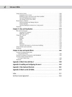
FIGURE 3.10
The Edit OBJ-Export Presets dialog box lets you change the settings for multiple formats quickly.
Exporting to the JSR-184 (M3G) format
The JSR-184 export option lets you save a scene to a format that can be viewed on mobile devices that sup-
port the Java 2 Micro Edition standard interface, such as mobile phones and PDA devices.
Because wireless devices have such a limited bandwidth, the JSR-184 Exporter dialog box, shown in
Figure 3.11, includes several options for optimizing the exported scene. This dialog box lists the Max scene
hierarchy, the JSR-184 scene hierarchy, and the parameters for the selected scene object. Using the toolbar
buttons at the top of the dialog box, you can change the hierarchy that is to be exported.
Before a scene can be exported, the Max scene must include a camera and you must specify an Active
Camera in the JSR-184 Exported dialog box. When a material map is selected from the JSR-184 hierarchy
list, the Texture Tool icon on the toolbar becomes active. Clicking this button opens the Texture Tool dialog
box, shown in Figure 3.12, where you can precisely control the size and format of the exported maps.
91
Working with Files, Importing, and Exporting
3
07_381304-ch03.qxp 7/7/08 3:04 PM Page 91
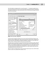
FIGURE 3.11
The JSR-184 Export dialog box lets you choose which resources to export.
FIGURE 3.12
The Texture Tool lets you specify the exact size of texture maps to be exported for mobile devices.
Remove Object
Convert Mesh to Sprite
Add World Object
New
JSR-184
Scene
Texture Tool
Add Group
Add
3ds Max
Scene
92
Getting Started with 3ds Max
Part I
07_381304-ch03.qxp 7/7/08 3:04 PM Page 92
To view the exported M3G files, the default installation of Max includes an M3G Player, which can be found
along with the other Max programs in Start ➪ Programs ➪ Autodesk ➪ 3ds Max 2009 ➪ JSR Viewer. To use
this player, the Java Runtime Environment needs to be installed. You can install it from the Max setup disc.
The JSR Viewer application is built using Java. If you’re having trouble with the viewer, try
installing the latest Java version from the installation DVD.
Exporting to the DWF format
The Design Web Format (DWF) is an ideal format for displaying your textured models to others via the
Web. It creates relatively small files that can be attached easily to an e-mail. You can use the File ➪ Publish
to DWF menu command to export the current scene to this format. This command opens a dialog box of
options that specify to Group by Object or Group by Layer. You also can choose to publish the Object
Properties, Materials, Selected Objects Only, or Hidden Objects. Another option is to Rescale Bitmaps to a
size entered in pixels.
Saved files can be viewed in the Autodesk DWF Viewer, shown in Figure 3.13. The Autodesk DWF Viewer
can be downloaded for free from the Autodesk Web site. This provides a way for users without Max
installed to view models.
FIGURE 3.13
The Autodesk DWF Viewer is used to view files exported using the DWF format.
The Autodesk DWF Viewer is automatically installed along with 3ds Max. If you want to view the exported
files in the viewer, simply enable the Show DWF in Viewer option in the DWF Publish Options dialog box.
The viewer includes controls for transforming the model, changing its shading and view, and printing the
current view.
Open
Copy to Clipboard
Orbit
Pan Zoom tools
NOTE
NOTE
93
Working with Files, Importing, and Exporting
3
07_381304-ch03.qxp 7/7/08 3:04 PM Page 93
Exporting utilities
In addition to the menu commands found in the File menu, Max includes a couple of utilities that export
specific information: the Lighting Data Export Utility and the Material XML Exporter Utility. You can access
these utilities from the Utilities panel in the Command Panel by clicking the More button and selecting
them from the pop-up list that appears.
Lighting Data Export Utility
The Lighting Data Export Utility exports exposure control data for a scene’s Illuminance and Luminance
values. These files can be saved as PIC or TIF files, which you can select in the 2D Lighting Data Exporter
rollout. You also can set an image’s Width and Height dimensions.
Exposure Control must be enabled for this utility to be enabled. You can learn about exposure
control in Chapter 45, “Using Atmospheric and Render Effects.”
Material XML Exporter Utility
The Material XML Exporter Utility exports a selected material to an XML file format, where it can be easily
shared with other users. After you select this utility, the Parameters rollout offers four options for selecting
the material to export: the Material/Map Browser, the Object List, Pick Object in Scene, and All Objects in
Scene.
The utility also offers several export options including Native XML, export to an Autodesk Tool Catalog,
and using an XSLT template. You also can select to export the material with a thumbnail and along with its
mapping modifiers.
Tutorial: Importing vector drawings from Illustrator
In most companies, a professional creative team uses an advanced vector drawing tool such as Illustrator to
design the company logo. If you need to work with such a logo, learning how to import the externally cre-
ated file gives you a jumpstart on your project.
When importing vector-based files into Max, only the lines are imported. Max cannot import
fills, blends, or other specialized vector effects. All imported lines are automatically converted
to Bézier splines in Max.
Although Max can draw and work with splines, this feature takes a backseat to the vector functions avail-
able in Adobe Illustrator. If you have an Illustrator (AI) file, you can import it directly into Max.
To import Adobe Illustrator files into Max, follow these steps:
1. Within Illustrator, save your file as “Box It Up Co logo” using the .ai file format by choosing File ➪
Save As.
When saving the Illustrator file, don’t use the latest file format. For this example, I’ve saved the
file using the Illustrator 8 format instead of the latest Illustrator CS, CS2, or CS3 formats.
Figure 3.14 shows a logo created using Illustrator.
NOTE
NOTE
NOTE
NOTE
CAUTION
CAUTION
94
Getting Started with 3ds Max
Part I
07_381304-ch03.qxp 7/7/08 3:04 PM Page 94
FIGURE 3.14
A company logo created in Illustrator and ready to save and import into Max
2. Open Max, and choose File ➪ Import.
A file dialog box opens.
3. Select Adobe Illustrator (AI) as the File Type. Locate the file to import, and click OK.
The AI Import dialog box asks whether you want to merge the objects with the current scene or
replace the current scene.
4. For your purposes, select the replace the current scene option and click OK.
5. The Shape Import dialog box asks whether you want to import the shapes as single or multiple
objects. Select multiple, and click OK.
Figure 3.15 shows the logo after it has been imported into Max. Notice that all the fills are missing.
95
Working with Files, Importing, and Exporting
3
07_381304-ch03.qxp 7/7/08 3:04 PM Page 95
FIGURE 3.15
A company logo created in Illustrator and imported into Max
Spline objects that are imported from Illustrator appear in Max as Editable Spline objects. You can
learn more about Editable Splines in Chapter 12, “Drawing and Editing 2D Splines and Shapes.”
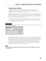
Using the File Utilities
With all these various files floating around, Max has included several utilities that make working with them
easier. The Utilities panel of the Command Panel includes several useful utilities for working with files. You
can access these utilities by opening the Utilities panel and clicking the More button to see a list of available
utilities.
Using the Asset Browser utility
The Asset Browser utility is the first default button in the Utility panel. Clicking this button opens the Asset
Browser window. The Asset Browser resembles Windows Explorer, except that it displays thumbnail images of
all the supported formats contained within the current directory. Using this window, shown in Figure 3.16,
you can browse through directory files and see thumbnails of images and scenes.
Even though thumbnails aren’t visible in Windows Vista, thumbnails are visible when you use
Asset Browser.
NOTE
NOTE
CROSS-REF
CROSS-REF
96
Getting Started with 3ds Max
Part I
07_381304-ch03.qxp 7/7/08 3:04 PM Page 96
FIGURE 3.16
The Asset Browser window displays thumbnails of the files in the current directory.
The supported file types include AVI, BMP, CIN, CEL, DDS, GIF, HDRI, IFL, IPP, JPEG, MPEG, PNG, PSD,
MOV, RGB, RLA, RPF, VST, TIF, and YUV. These types are the same ones that the File ➪ View Image File
command can open. All files with these extensions are viewable within the Asset Browser. You can select to
view only a certain type of file using the Filter menu. You also can view and filter MAXScript and AutoCAD
DWG files.
Open and display the Asset Manager within a viewport by right-clicking the viewport title and
choosing Views ➪ Extended ➪ Asset Manager from the pop-up menu.
You also can drag and drop files from the Asset Browser window to Max. Drag a scene file, and drop it on
Max’s title bar to open the scene file within Max. You can drop image files onto the map buttons in the
Material Editor window or drop an image file onto a viewport to make a dialog box appear, which lets you
apply the image as an Environment Map or as a Viewport Background, respectively.
The Asset Browser window is modeless, so you can work with the Max interface while the Asset Browser
window is open. Double-clicking an image opens it full size in the Rendered Frame window.
The Asset Browser also can act as a Web browser to look at content online. When the Asset Browser first
opens, a dialog box reminds you that online content may be copyrighted and cannot be used without con-
sent from the owner.
The Display menu includes three panes that you can select. The Thumbnail pane shows the files as thumb-
nails. You can change the size of these thumbnails using the Thumbnails menu. The Explorer pane displays
the files as icons the same as you would see in Windows Explorer. The Web pane displays the Web page for
the site listed in the Address field.
To view Web sites, you need to be connected to the Internet. The Asset Browser can remember your favorite
Web sites using the Favorites menu. The Asset Browser window also includes the standard Web browser
navigation buttons, such as Back, Forward, Home, Refresh, and Stop. You also can find these commands in
the Browse menu.
TIP
TIP
97
Working with Files, Importing, and Exporting
3
07_381304-ch03.qxp 7/7/08 3:04 PM Page 97
Max keeps thumbnails of all the images you access in its cache. The cache is a directory that holds thumb-
nails of all the recently accessed images. Each thumbnail image points to the actual directory where the
image is located. Choose File ➪ Preferences to open the Preferences dialog box, in which you can specify
where you want the cache directory to be located. To view the cached files, choose Filter ➪ All in Cache.
The Preferences dialog box also includes options to define how to handle dropped files. The options include
Always Merge or Import, Always XRef, or Ask Each Time.
Choose File ➪ Print to print the file view or Web window.
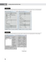
Finding files with the Max File Finder utility
Another useful utility for locating files is the Max File Finder utility, which you get to by using the More
button in the Utilities panel. When you select this utility, a rollout with a Start button appears in the Utility
panel. Clicking this button opens the MAXFinder dialog box. Using MAXFinder, you can search for scene
files by any of the information listed in the File Properties dialog box.
You can use the Browse button to specify the root directory to search. You can select to have the search also
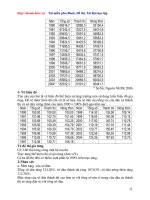
examine any subfolders. Figure 3.17 shows the MAXFinder dialog box locating all the scene files that
include the word blue.
FIGURE 3.17
You can use the MAXFinder utility to search for scene files by property.
Collecting files with the Resource Collector utility
When a scene is created, image and object files can be pulled from several different locations. The Resource
Collector utility helps you consolidate all these files into one location. The settings for this utility appear in
the Parameters rollout in the Utility panel of the Command Panel, as shown in Figure 3.18. The Output
Path is the location where the files are collected. You can change this location using the Browse button.
The utility includes options to Collect Bitmaps, to include the Max scene file, and to compress the files into
a compressed WinZip file. The Copy option makes copies of the files, and the Move option moves the
actual file into the directory specified in the Output Path field. The Update Materials option updates all
material paths in the Material Editor. When you’re comfortable with the settings, click the Begin button to
start the collecting.
98
Getting Started with 3ds Max
Part I
07_381304-ch03.qxp 7/7/08 3:04 PM Page 98
FIGURE 3.18
The Resource Collector utility can compile all referenced files into a single location.
Using the File Link Manager utility
The File Link Manager utility (which also can be accessed using the File ➪ File Link Manager menu) lets
you use external AutoCAD and Revit files in the same way that you use Max’s XRef features. By creating
links between the current Max scene and an external AutoCAD or Revit file, you can reload the linked file
when the external AutoCAD or Revit file has been updated and see the updates within Max.
This utility is divided into three panels — Attach, Files, and Presets. The Attach panel includes a File button
to select and open a DWG or DXF file. The Attach panel also includes options to rescale the file units, a
button to select which layers to include, and a button to attach the file. The Files panel displays each linked
AutoCAD file along with icons to show if the linked file has changed. A Reload button allows you to click to
reload the linked file within Max. The Preset panel lets you define file linking presets.
Using i-drop
To make accessing needed files from the Web even easier, Autodesk has created a technology known as
i-drop that lets you drag files from i-drop supported Web pages and drop them directly into Max. With
i-drop, you can drag and drop Max-created light fixture models, textures, or any other Max-supported file
from a light manufacturer’s Web site into your scene without importing and positioning a file. This format
allows you to add geometry, photometric data, and materials.
Accessing File Information
As you work with files, several dialog boxes in Max supply you with extra information about your scene.
You can use this information to keep track of files and record valuable statistics about a scene.
Displaying scene information
If you like to keep statistics on your files (to see whether you’ve broken the company record for the model
with the greatest number of faces), you’ll find the Summary Info dialog box useful. Use the File ➪ Summary
Info menu command to open a dialog box that displays all the relevant details about the current scene, such
as the number of objects, lights, and cameras; the total number of vertices and faces; and various model set-
tings, as well as a Description field where you can describe the scene. Figure 3.19 shows the Summary Info
dialog box.
99
Working with Files, Importing, and Exporting
3
07_381304-ch03.qxp 7/7/08 3:04 PM Page 99
FIGURE 3.19
The Summary Info dialog box shows all the basic information about the current scene.
The Plug-In Info button on the Summary Info dialog box displays a list of all the plug-ins currently installed
on your system. Even without any external plug-ins installed, the list is fairly long because many of the core
features in Max are implemented as plug-ins. The Summary Info dialog box also includes a Save to File but-
ton for saving the scene summary information as a text file.
Viewing file properties
As the number of files on your system increases, you’ll be wishing you had a card catalog to keep track of
them all. Max has an interface that you can use to attach keywords and other descriptive information about
the scene to the file. The File ➪ File Properties menu command opens the File Properties dialog box. This
dialog box, shown in Figure 3.20, includes three panels: Summary, Contents, and Custom. The Summary
panel holds information such as the Title, Subject, and Author of the Max file and can be useful for manag-
ing a collaborative project. The Contents panel holds information about the scene, such as the total number
of objects and much more. Much of this information also is found in the Summary Info dialog box. The
Custom panel, also shown in Figure 3.20, includes a way to enter a custom list of properties such as client
information, language, and so on.
You also can view the File Properties dialog box information while working in Windows
Explorer by right-clicking the file and selecting Properties. Three unique tabs are visible:
Summary, Contents, and Custom. The Summary tab holds the file identification information, including the
Title, Subject, Author, Category, Keywords, and Comments.
Viewing files
Sometimes looking at the thumbnail of an image isn’t enough to help you decide whether you have the
right image. For these cases, you can quickly load the image in question into a viewer to look at it closely.
The File ➪ View Image File menu command opens the View File dialog box shown in Figure 3.21. This dia-
log box lets you load and view graphic and animation files using the Rendered Frame Window or the
default Media Player for your system.
NOTE
NOTE
100
Getting Started with 3ds Max
Part I
07_381304-ch03.qxp 7/7/08 3:04 PM Page 100
FIGURE 3.20
The File Properties dialog box contains workflow information such as the scene author, comments, and revision dates.
FIGURE 3.21
The View File dialog box can open an assortment of image and animation formats.
The Rendered Frame Window is discussed in more detail in Chapter 22, “Learning to Render a
Scene.”
CROSS-REF
CROSS-REF
101
Working with Files, Importing, and Exporting
3
07_381304-ch03.qxp 7/7/08 3:04 PM Page 101
The View File dialog box includes several controls for viewing files. The Devices and Setup buttons let you
set up and view a file using external devices such as video recorders. The Info button lets you view detailed
information about the selected file. The View button opens the file for viewing while leaving the View File
dialog box open. The Open button opens the selected file and closes the dialog box. At the bottom of the
View File dialog box, the statistics and path of the current file are displayed.
The View File dialog box can open many types of files, including Microsoft videos (AVI), MPEG files,
bitmap images (BMP), Kodak Cineon images (CIN), Combustion files (CWS), Graphics Image Format
images (GIF), Radiance HDRI image files (HDR), Image File List files (IFL), JPEG images (JPG), OpenEXR
image files (EXR), Portable Network Graphics images (PNG), Adobe Photoshop images (PSD), QuickTime
movies (MOV), SGI images (RGB), RLA images, RPF images, Targa images (TGA, VST), Tagged Image File
Format images (TIF), Abekas Digital Disk images (YUV), and DirectDraw Surface (DDS) images.
You use the Gamma area on the View File dialog box to specify whether an image uses its own gamma set-
tings or the system’s default setting, or whether an override value should be used.
Summary
Working with files lets you save your work, share it with others, and reload it for more work. This chapter
covered the following topics:
Creating, saving, opening, merging, and archiving files
Understanding the various import and export types
Importing models from other programs, such as Illustrator and Poser
Working with the file utilities, such as the Asset Browser
Using the Summary Info and File Properties dialog boxes to keep track of scene files
By now, you should be feeling more comfortable with the user interface, but if you want to make some
changes to the interface, the next chapter covers how to customize it.
102
Getting Started with 3ds Max
Part I
07_381304-ch03.qxp 7/7/08 3:04 PM Page 102
W
hen you get into a new car, one of the first things you do is to
rearrange the seat and mirrors. You do this to make yourself comfort-
able. The same principle can apply to software packages: Arranging
or customizing an interface makes it more comfortable to work with.
Early versions of Max allowed only minimal changes to the interface, but later ver-
sions enable significant customization. The Max interface can be customized to
show only the icons and tools that you want to see. Max also has a rather bulky
set of preferences that you can use to set almost every aspect of the program. This
chapter covers various ways to make the Max interface more comfortable for you.
Using the Customize User
Interface Window
The Customize menu provides commands for customizing and setting up the
Max interface. The first menu item is the Customize User Interface menu com-
mand. This command opens the Customize User Interface dialog box. This dia-
log box includes five panels: Keyboard, Toolbars, Quads, Menus, and Colors. You
can also access this dialog box by right-clicking any toolbar away from the but-
tons and selecting Customize from the pop-up menu.
Customizing keyboard shortcuts
If used properly, keyboard shortcuts can increase your efficiency dramatically.
Figure 4.1 shows the Keyboard panel of the Customize User Interface dialog box.
In this panel, you can assign shortcuts to any command and define sets of short-
cuts. You can assign keyboard shortcuts for any of the interfaces listed in the Group
drop-down list. When an interface is selected from the Group drop-down list, all its
commands are listed below, along with their current keyboard shortcuts. You can
disable the keyboard shortcuts for any of these interfaces using the Active option
located next to the drop-down list.
103
IN THIS CHAPTER
Using the Customize User
Interface dialog box
Creating custom keyboard
shortcuts, toolbars, quadmenus,
menus, and colors
Customizing the Command
Panel buttons
Loading and saving custom
interfaces
Configuring paths
Setting system units
Setting preferences
Customizing the Max
Interface and Setting
Preferences
08_381304-ch04.qxp 7/7/08 3:16 PM Page 103
To access the defined keyboard shortcuts for the various interfaces, the Keyboard Shortcut
Override Toggle button on the main toolbar must be enabled. If this button is disabled, then
only the keyboard shortcuts for the Main UI are active.
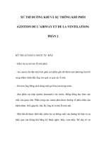
FIGURE 4.1
The Keyboard panel enables you to create keyboard shortcuts for any command.
Groups that have a large number of commands are split into categories. You can use the Category drop-
down list to filter only select types of commands. This helps you to quickly locate a specific type of com-
mand such as controllers, modifiers, or Space Warps. Entering a keyboard shortcut into the Hotkey field
shows in the Assigned to field whether that key is currently assigned to a command. You can Assign the
hotkey to the selected command or Remove the hotkey from its current assignment.
If the Overrides Active option is enabled, then the Editable Poly commands that are marked in bold text can
be activated by pressing and holding a keyboard shortcut. When you release the keyboard shortcut, the
original mode is restored. For example, if you are working in Extrude mode, you can press and hold the
Shift+Ctrl+B keyboard shortcut to access the Bevel command. When you release the keyboard shortcut, the
Extrude mode is active again. The amount of time that passes before the press-and-hold keyboard shortcut
becomes active is set by the Delay to Override value.
You can use the Write Keyboard Chart button to output all the keyboard commands to a text file. Using this
feature, you can print and post a chart of keyboard shortcuts next to your computer monitor. You can also
Load, Save, and Reset selected keyboard shortcut sets. Keyboard shortcut sets are saved as .kbd files in the
UI directory where Max is installed.
You can find a reference of the available default keyboard shortcuts in Bonus Chapter 2,
“3ds Max 2009 Keyboard Shortcuts.”
CROSS-REF
CROSS-REF
NOTE
NOTE
104
Getting Started with 3ds Max
Part I
08_381304-ch04.qxp 7/7/08 3:16 PM Page 104
Customizing toolbars
You can use the Customize User Interface dialog box’s Toolbar panel to create custom toolbars. Figure 4.2
shows this panel.
FIGURE 4.2
The Toolbars panel in the Customize User Interface dialog box enables you to create new toolbars.
The Toolbars panel of the Customize User Interface dialog box includes the same Group and Category
drop-down lists and command list as the Keyboard panel. Clicking the New button opens a simple dialog
box where you can name the new toolbar. The Delete button lets you delete toolbars. You can delete only
toolbars that you’ve created. The Rename button lets you rename the current toolbar. The Hide option
makes the selected toolbar hidden.
Use the Load and Save buttons to load and save your newly created interface, including the new toolbar, to
a custom interface file. Saved toolbars have the .cui extension.
After you create a new toolbar, you can drag the commands in the Action list to either a new blank toolbar
created with the New button or to an existing toolbar. By holding down the Alt key, you can drag a button
from another toolbar and move it to your new toolbar. Holding down the Ctrl key and dragging a button
retains a copy of the button on the first toolbar.
If you drag a command that has an icon associated with it, the icon appears on the new toolbar. If the com-
mand doesn’t have an icon, then the text for the command appears on the new toolbar.
105
Customizing the Max Interface and Setting Preferences
4
08_381304-ch04.qxp 7/7/08 3:16 PM Page 105
Tutorial: Creating a custom toolbar
If you’ve been using Max for a while, you probably have several favorite commands that you use extensively.
You can create a custom toolbar of all your favorite commands. To learn how to do this, you’ll create a cus-
tom toolbar for the compound objects.
To create a custom toolbar for creating compound objects, follow these steps:
1. Open the Customize User Interface dialog box by choosing Customize ➪ Custom User Interface.
2. Open the Toolbars panel, and click the New button. In the New Toolbar dialog box that appears,
name the toolbar Compound Objects. After you click OK, a new blank toolbar appears.
3. Select the Main UI group and the Objects Compounds category from the drop-down lists on the
left. Then drag each command in the Action list to the new blank toolbar.
4. Click the Save button to save the changes to the customized interface file. You can load the result-
ing toolbar from the Chap 04 directory on the DVD. It is named Compound Objects toolbar.cui.
Don’t be alarmed if the toolbar icons show up gray. Gray icons are simply disabled. When the
tool is enabled, they are shown in color.
Figure 4.3 shows the new toolbar. With the new toolbar created, you can float, dock, or edit this toolbar
just like the other toolbars. Notice that some of the tools have icons and others have text names.
FIGURE 4.3
A new toolbar of compound objects created using the Customize User Interface dialog box
You can right-click any of the buttons on any of the existing toolbars, except for the main toolbar, to access
a pop-up menu. This pop-up menu enables you to change the button’s appearance, delete the button, edit
the button’s macro script, or open the Customize User Interface dialog box.
To learn more about editing macro scripts, see Chapter 49, “Automating with MAXScript.”
Changing a button’s appearance
Selecting the Edit Button Appearance command from the right-click pop-up menu opens the Edit Macro
Button dialog box, shown in Figure 4.4. This dialog box enables you to quickly change the button’s icon,
tooltip, or text label. Each icon group shows both the standard icon and the grayed-out disabled version of
the icon. Default buttons can also be changed. The Odd Only check box shows only the standard icons.
If a text label doesn’t fit within the toolbar button, you can increase the button width using the
Fixed Width Text Buttons spinner in the General panel of the Preference Settings dialog box.
NOTE
NOTE
CROSS-REF
CROSS-REF
NOTE
NOTE
106
Getting Started with 3ds Max
Part I
08_381304-ch04.qxp 7/7/08 3:16 PM Page 106
FIGURE 4.4
The Edit Macro Button dialog box provides a quick way to change an icon, tooltip, or text label.
Tutorial: Adding custom icons
The Max interface uses two different sizes of icons. Large icons are 24 × 24 pixels, and small icons are 16 ×
15 pixels. Large icons can be 24-bit color, and small ones must be only 16-bit. Multiple icons can be placed
side by side in a single file. The easiest way to create some custom toolbars is to copy an existing set of icons
into an image-editing program, make the modifications, and save them under a different name. You can find
all the icons saved as BMPs and used by Max in the 3dsmax\UI\Icons directory.
To create a new group of icons, follow these steps:
1. Select a group of current icons to edit from the UI directory, and open them in Photoshop. I
selected the Patches group, which includes all the files that start with the word Patches. This
group includes only two icons. To edit icons used for both large and small icon settings and both
active and inactive states, open the following four files: Patches_16a.bmp, Patches_16i.bmp,
Patches_24a.bmp, and Patches_24i.bmp.
2. In each file, the icons are all included side by side in the same file, so the first two files are 32 × 15
and the second two are 48 × 24. Edit the files, being sure to keep each icon within its required
dimensions.
3. When you finish editing or creating the icons, save each file with the name of the icon group in front
of the underscore character. My files were saved as Kels_16a.bmp, Kels_16i.bmp, Kels_24a.bmp,
and Kels_24i.bmp, so they show up in Kels group in the Edit Macro Button dialog box. Copy these
four edited files from the Chap 04 directory on the DVD to the 3dsmax\UI\Icons directory.
4. After the files are saved, you need to restart Max. The icon group is then available within the
Customize User Interface dialog box when assigned to a command.
Figure 4.5 shows the Edit Macro Button dialog box with my custom icon group named Kels open.
107
Customizing the Max Interface and Setting Preferences
4
08_381304-ch04.qxp 7/7/08 3:17 PM Page 107
FIGURE 4.5
The Edit Macro Button dialog box with a custom icon group selected
Customizing quadmenus
The third panel in the Customize User Interface dialog box allows you to customize the quadmenus. You
can open quadmenus by right-clicking on the active viewport or in certain interfaces. Figure 4.6 shows this
panel.
FIGURE 4.6
The Quads panel of the Customize User Interface dialog box lets you modify pop-up quadmenus.
108
Getting Started with 3ds Max
Part I
08_381304-ch04.qxp 7/7/08 3:17 PM Page 108
To the left of the panel are the Group and Category drop-down lists and a list of actions that are the same as
those that appear in the Keyboard and Toolbars panels, but the Quads panel also includes a Separator and a
list of Menu commands. Quadmenus can include separators to divide the commands into different sections
and menus that appear at the top of the standard interface.
The drop-down list at the top right of the Quads panel includes many different quadmenu sets. These quad-
menus appear in different locations, such as within the ActiveShade window. Not only can you customize
the default viewport quadmenus, but you also can create your own named custom quadmenus with the
New button or you can rename an existing quadmenu. The Quad Shortcut field lets you assign a keyboard
shortcut to a custom quadmenu.
Several quadmenus have keyboard shortcuts applied to them. Right-clicking with the Shift key
held down opens the Snap quadmenu. Other shortcuts include Alt+right-click for the
Animation quadmenu, Ctrl+right-click for the Modeling quadmenu, Shift+Alt+right-click for the reactor
quadmenu, and Ctrl+Alt+right-click for the Lighting/Rendering quadmenu.
If the Show All Quads option is disabled, it causes only a single quadmenu to be shown at a time when
unchecked. Although only one quadmenu is shown at a time, the corner of each menu is shown, and you
can switch between the different menus by moving the mouse over the corner of the menu. This is useful if
you want to limit the size of the quadmenu.
The four quadrants of the current quadmenu are shown as four boxes. The currently selected quadmenu is
highlighted yellow, and its label and commands are shown in the adjacent fields. Click the gray boxes to
select one of the different quadmenus.
To add a command to the selected quadmenu, drag an action, separator, or menu from the panes on the left
to the quadmenu commands pane on the right. You can reorder the commands in the quadmenu com-
mands pane by dragging the commands and dropping them in their new location. To delete a command,
just select it and press the Delete key or select Delete Menu Item from the right-click pop-up menu.
If you right-click on the commands in the right pane, a pop-up menu appears with options to delete or
rename the command. Another command allows you to flatten a submenu, which displays all submenu
commands on the top level with the other commands.
Custom quadmenus can be loaded and saved as menu files (with the .mnu extension).
The Quads panel also includes an Advanced Options button. Clicking this button opens the Advanced
Quad Menu Options dialog box, shown in Figure 4.7. Using this dialog box, you can set options such as
the colors used in the quadmenus.
Changes to the Advanced Quad Menu Options dialog box affect all quadmenus. You can load and save these
settings to files (with the .qop extension). The Starting Quadrant determines which quadrant is first to appear
when the quadmenu is accessed. You can select to change the colors for each quadmenu independent of the
others. The column with the L locks the colors so they are consistent for all quadmenus if enabled.
The remainder of the Advanced Quad Menu Options dialog box includes settings for controlling how the
quadmenus are displayed and positioned, as well as the fonts that are used.
The Animation section lets you define the animation style that is used when the quadmenus appear. The ani-
mation types include None, Stretch, and Fade. The Stretch style slowly stretches the quadmenus until they
are full size over the designated number of steps, and the Fade style slowly makes the quadmenus appear.
I personally don’t like to wait for the quadmenus to appear, so I keep the Animation setting set
to None.
TIP
TIP
TIP
TIP
109
Customizing the Max Interface and Setting Preferences
4
08_381304-ch04.qxp 7/7/08 3:17 PM Page 109
FIGURE 4.7
The Advanced Quad Menu Options dialog box lets you change quadmenu fonts and colors.
Customizing menus
The Menus panel of the Customize User Interface dialog box allows you to customize the menus used at the
top of the Max window. Figure 4.8 shows this panel.
FIGURE 4.8
You can use the Menus panel of the Customize User Interface dialog box to modify menus.
110
Getting Started with 3ds Max
Part I
08_381304-ch04.qxp 7/7/08 3:17 PM Page 110
This panel includes the same Group and Category drop-down lists and the Action, Separator, and Menus
panes found in the Quads panel. You can drag and drop these commands to the menu pane on the right.
Menus can be saved as files (with the .mnu extension). In the menu pane on the right, you can delete menu
items with the Delete key or by right-clicking and selecting Delete Item from the pop-up menu.
If you place an ampersand (&) character in front of a custom menu name letter, that letter is
underlined and can be accessed using the Alt key; for example, Alt+F opens the File menu.
Tutorial: Adding a new menu
Adding a new menu is easy to do with the Customize User Interface dialog box. For this example, you tack
another menu to the end of the Tools menu.
To add another menu item to the Tools menu, follow these steps:
1. Choose Customize ➪ Customize User Interface to open the Customize User Interface dialog box.
2. Click the Menus tab to open the Menus panel.
3. In the top-left drop-down list, select Main UI from the Group drop-down list and Tools from the
Category drop-down list.
Expand the Tools menu in the right pane by clicking on the plus sign to its left.
4. Locate the Cross Hair Cursor Toggle menu item in the Action list, drag it to the right, and drop it
right after the Channel Info Editor menu item.
As you drag, a blue line indicates where the menu will be located.
5. Click the Save button to save the menu as a file. You can find the customized menu from this
example in the Chap 04 directory on the DVD.
After you save the new menu file, you need to restart Max before you can see the changes. You can reset the
default UI by choosing Customize ➪ Revert to Startup Layout.
Customizing colors
Within Max, the colors often indicate the mode in which you’re working. For example, red marks anima-
tion mode. Using the Colors panel of the Customize User Interface dialog box, you can set custom colors
for all Max interface elements. This panel, shown in Figure 4.9, includes two panes. The upper pane dis-
plays the available items for the interface selected in the Elements drop-down list. Selecting an item in the
list displays its color in the color swatch to the right.
The lower pane displays a list of the custom colors that can be changed to affect the appearance of the inter-
face. For example, Highlight Text isn’t an element; it’s an interface appearance. The Scheme drop-down list
can alter the color scheme between custom colors and the Windows Default Colors.
You can save custom color settings as files with the .clr extension. You can use the Apply Colors Now but-
ton to immediately update the interface colors.
TIP
TIP
111
Customizing the Max Interface and Setting Preferences
4
08_381304-ch04.qxp 7/7/08 3:17 PM Page 111
FIGURE 4.9
You can use the Colors panel of the Customize User Interface dialog box to set the colors used in the interface.
Customizing Modify and Utility Panel Buttons
The Modify panel and the Utilities panel in the Command Panel both include a button called Configure
Button Sets that allows you to configure how the modifiers are grouped and which utility buttons appear in
the Utilities panel.
In the Modify panel, the Configure Modifier Sets button is the right-most button directly under the Modifier
Stack. This button opens a pop-up menu that lists all the modifier categories. The top pop-up menu com-
mand is Configure Modifier Sets, which opens a dialog box, shown in Figure 4.10, when selected. Using
this dialog box, you can control which modifiers are grouped with which sets.
To add a modifier to a set, select the set from the Sets drop-down list and drag the modifier from the list of
Modifiers on the left to the button set on the right. To create a new set, simply type a new name into the
Sets field. After a set has changed, you need to save it with the Save button.
You can find the same Configure Button Sets button on the Utilities panel. Clicking this button opens a sim-
ilar dialog box where you can drag from a list of Utilities to a list of buttons on the right. These buttons are
then displayed in the Utilities panel.
112
Getting Started with 3ds Max
Part I
08_381304-ch04.qxp 7/7/08 3:17 PM Page 112
FIGURE 4.10
The Configure Modifier Sets dialog box lets you group the modifiers as you want.
Working with Custom Interfaces
If you’ve changed your interface, you’ll be happy to know that the Customize menu includes a way for you to
save and then reload your custom setup. This feature is especially helpful for users who share a copy of Max.
Any custom .ui file can be loaded as the default interface from the command line by adding a –c
and the .ui filename after the 3dsmax.exe file (for example, 3dsmax.exe –c my_interface.ui).
Saving and loading a custom interface
Custom interface schemes are saved with the .ui extension using the Customize ➪ Save Custom UI Scheme
menu command. When you save a custom scheme, Max opens a file dialog box where you can name the .ui
file, and then the Custom Scheme dialog box, shown in Figure 4.11. This dialog box lets you choose which
customizations to include in the custom scheme. It also lets you select the icon type to use. The options are
Classic and 2D Black and White.
FIGURE 4.11
The Custom Scheme dialog box appears when you’re saving a custom interface and lets you select which items to
include.
TIP
TIP
113
Customizing the Max Interface and Setting Preferences
4
08_381304-ch04.qxp 7/7/08 3:17 PM Page 113
You can load saved user interface schemes with Customize ➪ Load Custom UI. These custom UI files are
saved in the Program Files ➪ Autodesk ➪ 3ds Max 2009 ➪ UI folder. The default Max install includes sev-
eral predefined interface setups located in the UI directory. These standard interfaces are available:
DefaultUI: Default interface that opens when Max is first installed.
Ame-dark: Displays the standard interface with black windows, backgrounds, and viewports. All
the icons and menus are light gray, and many of the icons are different, as shown in Figure 4.12.
Ame-light: Same as the Ame-dark layout, except the icons and menus are black and the back-
grounds are all light gray. Many icons are different here, too.
ModularToolbarsUI: An interface that breaks the main toolbar into many smaller toolbars that
are easier to move and arrange.
You also can use both the Load Custom UI and Save Custom UI menu commands to save and load any of
the custom user interface files types, including these:
Interface Scheme files (.ui)
UI files (.cui)
Menu files (.mnu)
Color files (.clr)
Keyboard Shortcut files (.kbd)
Quadmenu Options files (.qop)
FIGURE 4.12
If you prefer a darker interface, then try loading the Ame-dark scheme.
114
Getting Started with 3ds Max
Part I
08_381304-ch04.qxp 7/7/08 3:17 PM Page 114