kelly l murdock 3ds Max 2009 Bible phần 3 docx
Bạn đang xem bản rút gọn của tài liệu. Xem và tải ngay bản đầy đủ của tài liệu tại đây (9.99 MB, 151 trang )
T
he only thing better than one perfect object is two perfect objects.
Cloning objects is the process of creating copies of objects. These copies
can maintain an internal connection (called an instance or a reference)
to the original object that allows them to be modified along with the original
object. For example, if you create a school desk and clone it multiple times as an
instance to fill a room, then changing the parameter of one of the desks automati-
cally changes it for all the other desks also.
An array is a discrete set of regularly ordered objects. So creating an array of
objects involves cloning several copies of an object in a pattern, such as in rows
and columns or in a circle.
I’m sure you have the concept for that perfect object in your little bag of tricks,
and this chapter lets you copy it over and over after you get it out.
Cloning Objects
You can clone objects in Max in a couple of ways (and cloning luckily has noth-
ing to do with DNA or gene splices). One method is to use the Edit ➪ Clone
(Ctrl+V) menu command, and another method is to transform an object while
holding down the Shift key. You won’t need to worry about these clones attacking
anyone (unlike Star Wars: Episode II).
Using the Clone command
You can create a duplicate object by choosing the Edit ➪ Clone (Ctrl+V) menu
command. You must select an object before the Clone command becomes active,
and you must not be in a Create mode. Selecting this command opens the Clone
Options dialog box, shown in Figure 8.1, where you can give the clone a name
and specify it as a Copy, Instance, or Reference. You can also copy any controllers
associated with the object as a Copy or an Instance.
219
IN THIS CHAPTER
Cloning objects
Understanding copies, instances,
and references
Using the Mirror and Snapshot
tools
Spacing clones along a path with
the Spacing tool
Using the Clone and Align tool
Creating object arrays
Using the Ring Array system
Cloning Objects and
Creating Object Arrays
13_381304-ch08.qxp 7/7/08 3:02 PM Page 219
The Edit menu doesn’t include the common Windows cut, copy, and paste commands because
many objects and subobjects cannot be easily pasted into a different place. However, you will
find a Clone (Ctrl+V) command, which can duplicate a selected object.
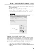
FIGURE 8.1
The Clone Options dialog box defines the new object as a Copy, Instance, or Reference.
The difference between Copy, Instance, and Reference is discussed in the “Understanding
Cloning Options” section in this chapter.
When a clone is created with the Clone menu, it is positioned directly on top of the original, which makes
distinguishing it from the original difficult. To verify that a clone has been created, open the Select by Name
dialog box by pressing H and look for the cloned object (it has the same name, but an incremented number
has been added). To see both objects, click the Select and Move button on the main toolbar and move one
of the objects away from the other.
Using the Shift-clone method
An easier way to create clones is with the Shift key. You can use the Shift key when objects are transformed
using the Select and Move, Select and Rotate, and Select and Scale commands. Holding down the Shift key
while you use any of these commands on an object clones the object and opens the Clone Options dialog
box. This Clone Options dialog box is identical to the dialog box previously shown, except it includes a
spinner to specify the number of copies.
Performing a transformation with the Shift key held down defines an offset that is applied repeatedly to
each copy. For example, holding down the Shift key while moving an object five units to the left (with the
Number of Copies set to 5) places the first cloned object five units away from the original, the second
cloned object ten units away from the original object, and so on.
Tutorial: Cloning dinosaurs
The story behind Jurassic Park is pretty exciting, but in Max you can clone dinosaurs without their DNA.
To investigate cloning objects, follow these steps:
1. Open the Cloning dinosaurs.max file found in the Chap 08 directory of the DVD.
2. Select the dinosaur object by clicking it in one of the viewports.
3. With the dinosaur model selected, choose Edit ➪ Clone (or press Ctrl+V).
The Clone Options dialog box appears.
CROSS-REF
CROSS-REF
CAUTION
CAUTION
220
Working with Objects
Part II
13_381304-ch08.qxp 7/7/08 3:02 PM Page 220
4. Name the clone First clone, select the Copy option, and click OK.
5. Click the Select and Move button (or press the W key) on the main toolbar. Then in the Top
viewport, click and drag the dinosaur model to the right.
As you move the model, the original model beneath it is revealed.
6. Select each model in turn, and notice the name change in the Create panel’s Name field. Notice
that the clone is even the same object color as the original.
7. With the Select and Move button still active, hold down the Shift key, click the cloned dinosaur in
the Top viewport, and move it to the right again. In the Clone Options dialog box that appears,
select the Copy option, set the Number of Copies to 3, and click OK.
8. Click the Zoom Extents All button (or press Shift+Ctrl+Z) in the lower-right corner to view all the
new dinosaurs.
Three additional dinosaurs have appeared, equally spaced from each other. The spacing was deter-
mined by the distance that you moved the second clone before releasing the mouse. Figure 8.2
shows the results of our dinosaur cloning experiment. (Now you’ll need to build a really strong
fence.)
FIGURE 8.2
Cloning multiple objects is easy with the Shift-clone feature.
221
Cloning Objects and Creating Object Arrays
8
13_381304-ch08.qxp 7/7/08 3:02 PM Page 221
Understanding Cloning Options
When cloning in Max, you’re offered the option to create the clone as a copy, an instance, or a reference.
This is true not only for objects, but for materials, modifiers, and controllers as well.
Working with copies, instances, and references
When an object is cloned, the Clone Options dialog box appears. This dialog box enables you to select to
make a copy, an instance, or a reference of the original object. Each of these clone types is unique and offers
different capabilities.
A copy is just what it sounds like — an exact replica of the original object. The new copy maintains no ties
to the original object and is a unique object in its own right. Any changes to the copy do not affect the origi-
nal object, and vice versa.
Instances are different from copies in that they maintain strong ties to the original object. All instances of an
object are interconnected, so that any geometry modifications (done with modifiers or object parameters) to
any single instance changes all instances. For example, if you create several instances of a mailbox and then
use a modifier on one of them, all instances are also modified.
Instances and references can have different object colors, materials, transformations (moving,
rotating, or scaling), and object properties.
References are objects that inherit modifier changes from their parent objects, but do not affect the parent
when modified. Referenced objects get all the modifiers applied to the parent and can have their own modi-
fiers as well. For example, suppose that you have an apple object and a whole bunch of references to that
apple. Applying a modifier to the base apple changes all the remaining apples, but you can also apply a
modifier to any of the references without affecting the rest of the bunch.
Instances and references are tied to the applied object modifiers, which are covered in more
detail in Chapter 11, “Introducing Modifiers and Using the Modifier Stack.”
At any time, you can break the tie between objects with the Make Unique button in the Modifier Stack. The
Views ➪ Show Dependencies command shows in magenta any objects that are instanced or referenced
when the Modify panel is opened. This means that you can easily see which objects are instanced or refer-
enced from the current selection.
Tutorial: Creating instanced doughnuts
Learning how the different clone options work will save you lots of future modifications. To investigate
these options, you’ll take a quick trip to the local doughnut shop.
To clone some doughnuts, follow these steps:
1. Create a doughnut using the Torus primitive by selecting Create ➪ Standard Primitives ➪ Torus,
and then dragging and clicking twice in the Top viewport to create a torus object.
2. Click the torus object in the Top viewport to select it.
3. With the doughnut model selected, click the Select and Move button (or press the W key). Hold
down the Shift key, and in the Top viewport, move the doughnut upward. In the Clone Options
dialog box, select the Instance option, set the Number of Copies to 5, and click OK. Click the
Zoom Extents All (or press the Shift+Ctrl+Z key) button to widen your view.
CROSS-REF
CROSS-REF
NOTE
NOTE
222
Working with Objects
Part II
13_381304-ch08.qxp 7/7/08 3:02 PM Page 222
4. Select all objects with the Edit ➪ Select All (Ctrl+A) command, and then Shift+drag the doughnuts
in the Top viewport to the right. In the Clone Options dialog box, select the Instance option again
and 3 for the Number of Copies and click OK. This creates a nice array of two dozen doughnuts.
Click the Zoom Extents All button (or press the Ctrl+Shift+Z key) to see all the doughnuts.
5. Select a single doughnut, and in the Parameters rollout of the Modify panel, set Radius1 to 20 and
Radius2 to 10.
This makes a nice doughnut and changes all doughnuts at once.
6. Select the Modifiers ➪ Parametric Deformers ➪ Bend command. Then in the Parameters rollout of
the Command Panel, enter 25 in the Angle field and select the X Bend Axis.
This adds a slight bend to the doughnuts.
You can use modifiers to alter geometry. You can learn about using modifiers in Chapter 11,
“Introducing Modifiers and Using the Modifier Stack.”
Figure 8.3 shows the doughnuts all changed exactly the same. You can imagine the amount of time it would
take to change each doughnut individually. Using instances made these changes easy.
FIGURE 8.3
Two dozen doughnut instances ready for glaze
CROSS-REF
CROSS-REF
223
Cloning Objects and Creating Object Arrays
8
13_381304-ch08.qxp 7/7/08 3:02 PM Page 223
Tutorial: Working with referenced apples
Now that you have filled our bellies with doughnuts, you need some healthful food for balance. What better
way to add balance than to have an apple or two to keep the doctor away?
To create some apples using referenced clones, follow these steps:
1. Open the Referenced Apples.max file from the Chap 08 directory on the DVD.
2. Select the apple, and Shift+drag with the Select and Move (W) tool in the Top viewport to create a
cloned reference. Select the Reference option in the Clone Options dialog box. Then close the
Clone Options dialog box.
3. Select the original apple again, and repeat Step 2 until several referenced apples surround the
original apple.
4. Select the original apple in the middle again, and choose the Modifiers ➪ Subdivision Surfaces ➪
MeshSmooth command. In the Subdivision Amount rollout, set the number of Iterations to 2.
This smoothes all the apples.
5. Select one of the surrounding apples, and apply the Modifiers ➪ Parametric Deformers ➪ Taper
command. Set the Amount value to 0.5 about the Z-axis.
6. Select another of the surrounding apples, and apply the Modifiers ➪ Parametric Deformers ➪
Squeeze command. Set the Axial Bulge Amount value to 0.3.
7. Select another of the surrounding apples, and apply the Modifiers ➪ Parametric Deformers ➪
Squeeze command. Set the Radial Squeeze Amount value to 0.2.
8. Select another of the surrounding apples, and apply the Modifiers ➪ Parametric Deformers ➪
Bend command. Set the Angle value to 20 about the Z axis.
As you apply modifiers to a referenced object, notice the thick gray bar in the Modifier Stack.
This bar, called the Derived Object Line, separates which modifiers get applied to all refer-
enced objects (below the line) and which modifiers get applied to only the selected object (above the line).
If you drag a modifier from above the gray bar to below the gray bar, then that modifier is applied to all
references.
Using referenced objects, you can apply the major changes to similar objects, but still make minor changes
to objects to make them a little different. Figure 8.4 shows the apples. Notice that they are not all exactly
the same.
NOTE
NOTE
224
Working with Objects
Part II
13_381304-ch08.qxp 7/7/08 3:02 PM Page 224
FIGURE 8.4
Even apples from the same tree should be slightly different.
Mirroring Objects
Have you ever held the edge of a mirror up to your face to see half of your head in the mirror? Many objects
have a natural symmetry that you can exploit to require that only half an object be modeled. The human
face is a good example. You can clone symmetrical parts using the Mirror command.
Using the Mirror command
The Mirror command creates a clone (or No Clone if you so choose) of the selected object about the current
coordinate system. To open the Mirror dialog box, shown in Figure 8.5, choose Tools ➪ Mirror, or click the
Mirror button located on the main toolbar. You can access the Mirror dialog box only if an object is selected.
Within the Mirror dialog box, you can specify an axis or plane about which to mirror the selected object.
You can also define an Offset value. As with the other clone commands, you can specify whether the clone
is to be a Copy, an Instance, or a Reference, or you can choose No Clone, which flips the object around the
axis you specify. The dialog box also lets you mirror IK (inverse kinematics) Limits, which reduces the num-
ber of IK parameters that need to be set.
Learn more about inverse kinematics in Chapter 41, “Working with Inverse Kinematics.”
CROSS-REF
CROSS-REF
225
Cloning Objects and Creating Object Arrays
8
13_381304-ch08.qxp 7/7/08 3:02 PM Page 225
FIGURE 8.5
The Mirror dialog box can create an inverted clone of an object.
Tutorial: Mirroring a robot’s leg
Many characters have symmetry that you can use to your advantage, but to use symmetry, you can’t just
clone one half. Consider the position of a character’s right ear relative to its right eye. If you clone the ear,
then the position of each ear will be identical, with the ear to the right of the eye, which would make for a
strange looking creature. What you need to use is the Mirror command, which clones the object and rotates
it about a selected axis.
In this example, you have a complex mechanical robot with one of its legs created. Using Mirror, you can
quickly clone and position its second leg.
To mirror a robot’s leg, follow these steps:
1. Open the Robot mech.max file from the Chap 08 directory on the DVD.
This file includes a robot with one of its legs deleted.
2. Select all objects that make up the robot’s leg in the Left viewport, and open the Mirror dialog box
with the Tools ➪ Mirror menu command.
3. In the Mirror dialog box, select X as the Mirror Axis and Instance as the Clone Selection. Change
the Offset value until the cloned leg is in position, which should be at around –2.55.
The mirror axis depends on the viewport, so make sure that the Left viewport is selected.
Any changes made to the dialog box are immediately shown in the viewports.
4. Click OK to close the dialog box.
By making the clone selection an instance, you can ensure that any future modifications to the
right half of the figure are automatically applied to the left half.
Figure 8.6 shows the resulting robot — which won’t be falling over now.
NOTE
NOTE
NOTE
NOTE
226
Working with Objects
Part II
13_381304-ch08.qxp 7/7/08 3:02 PM Page 226
FIGURE 8.6
A perfectly symmetrical robot, compliments of the Mirror tool
Cloning over Time
Another useful way to create multiple copies of an object is to have an object be created based on its posi-
tion during a specific frame of an animation. This cloning at specific times is accomplished with the
Snapshot feature.
Using the Snapshot command
The Snapshot command creates static copies, instances, references, or even meshes of a selected object as it
moves along an animation path. For example, you could create a series of footprints by animating a set of
footprints moving across the screen from frame 1 to frame 100, and then choose Tools ➪ Snapshot and
enter the number of steps to appear over this range of frames in the Snapshot dialog box. The designated
number of steps is created at regular intervals for the animation range. Be aware that the Snapshot com-
mand works only with objects that have an animation path defined.
You can open the Snapshot dialog box by choosing Tools ➪ Snapshot or by clicking the Snapshot button
(under the Array flyout on the Extras toolbar). Snapshot is the second button in the flyout. In the Snapshot
dialog box, shown in Figure 8.7, you can choose to produce a single clone or a range of clones over a given
number of frames. Selecting Single creates a single clone at the current frame.
227
Cloning Objects and Creating Object Arrays
8
13_381304-ch08.qxp 7/7/08 3:02 PM Page 227
When you enter the number of Copies in the Snapshot dialog box, a copy is placed at both the
beginning and end of the specified range, so if your animation path is a closed path, two
objects are stacked on top of each other. For example, if you have a square animation path and you want to
place a copy at each corner, you need to enter a value of 5.
FIGURE 8.7
The Snapshot dialog box lets you clone a Copy, Instance, Reference, or Mesh.
The Snapshot tool can also be used with particle systems.
Tutorial: Creating a path through a maze
The Snapshot tool can be used to create objects as a model is moved along an animated path. In this exam-
ple, you create a series of footsteps through a maze.
To create a set of footprints through a maze with the Snapshot tool, follow these steps:
1. Open the Path through a maze.max file from the Chap 08 directory on the DVD. This file
includes a set of animated footprints that travel to the exit of a maze.
2. Select both footprint objects at the entrance to the maze.
3. Choose the Tools ➪ Snapshot menu to open the Snapshot dialog box. Select the Range option, set
the number of Copies to 20, and select the Instance option. Then click OK.
Figure 8.8 shows the path of footsteps leading the way through the maze, which are easier to follow than
breadcrumbs.
TIP
TIP
NOTE
NOTE
228
Working with Objects
Part II
13_381304-ch08.qxp 7/7/08 3:02 PM Page 228
FIGURE 8.8
The Snapshot tool helps to build a set of footprints through a maze.
Spacing Cloned Objects
The Snapshot tool offers a convenient way to clone objects along an animation path, but what if you want
to clone objects along a path that isn’t animated? The answer is the Spacing tool. The Spacing tool can posi-
tion clones at regular intervals along a path by either selecting a path and the number of cloned objects or
by picking two points in the viewport.
Using the Spacing tool
You access the Spacing tool by clicking on a button in the flyout under the Array button on the Extras tool-
bar (the Extras toolbar can be made visible by right-clicking on the main toolbar away from the buttons).
You can also access it using the Tools ➪ Align ➪ Spacing Tool (Shift+I) menu command. When accessed, it
opens the Spacing Tool dialog box, shown in Figure 8.9. At the top of this dialog box are two buttons: Pick
Path and Pick Points. If a path is selected, its name appears on the Pick Path button.
229
Cloning Objects and Creating Object Arrays
8
13_381304-ch08.qxp 7/7/08 3:02 PM Page 229
FIGURE 8.9
The Spacing Tool dialog box lets you select how to position clones along a path.
You can also specify Count, Spacing, Start Offset, and End Offset values. The drop-down list offers several
preset options, including Divide Evenly, Free Center, End Offset, and more. These values and preset options
are used to define the number and spacing of the objects. The spacing and position of the objects depend
on the values that are included. For example, if you include only a Count value, then the objects are evenly
spaced along the path including an object at each end. If an offset value is included, then the first or last
item is moved away from the end by the offset value. If a Spacing value is included, then the number of
objects required to meet this value is included automatically.
The Lock icons next to the Start and End Offset values force the Start or End Offset values to be the same as
the Spacing value. This has the effect of pushing the objects away from their end points.
Before you can use either the Pick Path or Pick Points buttons, you must select the object to be cloned. Using
the Pick Path button, you can select a spline path in the scene, and cloned objects are regularly spaced
according to the values you selected. The Pick Points method lets you click to select the Start point and click
again to select an end point. The cloned objects are spaced in a straight line between the two points.
The two options for determining the spacing width are Edges and Centers. The Edges option spaces objects
from the edge of its bounding box to the edge of the adjacent bounding box, and the Centers option spaces
objects based on their centers. The Follow option aligns the object with the path if the path is selected.
Each object can be a copy, instance, or reference of the original. The text field at the bottom of the dialog
box displays for your information the number of objects and the spacing value between each.
Lining up objects to correctly follow the path can be tricky. If the objects are misaligned, you
can change the object’s pivot point so it matches the viewport coordinates. This makes the
object follow the path with correct position.
You can continue to modify the Spacing Tool dialog box’s values while the dialog box is open, but the objects
are not added to the scene until you click the Apply button. The Cancel button closes the dialog box.
Tutorial: Stacking a row of dominoes
A good example of using the Spacing tool to accomplish something that is difficult in real life is to stack a
row of dominoes. It is really a snap in Max, regardless of the path.
TIP
TIP
230
Working with Objects
Part II
13_381304-ch08.qxp 7/7/08 3:02 PM Page 230
To stack a row of dominoes using the Spacing tool, follow these steps:
1. Open the Row of dominoes.max file from the Chap 08 directory on the DVD.
This file includes a single domino and a wavy spline path.
2. Select the domino object, and open the Spacing tool by selecting the flyout button under the
Array button on the Extras toolbar (or by pressing Shift+I).
3. In the Spacing Tool dialog box, click the Pick Path button and select the wavy path.
The path name appears on the Pick Path button.
4. From the drop-down list in the Parameters section of the Spacing Tool dialog box, select the
Count option with a value of 35.
This is the same as the Divide Evenly, Objects at Ends option in the drop-down list.
5. Select the Edges context option, check the Follow check box, and make all clones Instances. Click
Apply when the result looks right, and close the Spacing Tool dialog box.
Figure 8.10 shows the simple results. The Spacing Tool dialog box remains open until you click the Cancel
button.
FIGURE 8.10
These dominoes were much easier to stack than the set in my living room.
231
Cloning Objects and Creating Object Arrays
8
13_381304-ch08.qxp 7/7/08 3:02 PM Page 231
Using the Clone and Align Tool
Imagine you’re working on a production team and the modeler assigned to the project says he needs some
more time to make the building columns “something special.” Just as you prepare to give him the “deadlines
don’t die” speech, you remember the Clone and Align tool. Using this tool, you can place proxy objects
where the detailed ones are supposed to go. Then, when the detailed object is ready, the Clone and Align
tool lets you clone the detailed object and place it where all the proxies are positioned. This, of course,
makes the modeler happy and doesn’t disrupt your workflow. Another production team victory.
Aligning source objects to destination objects
Before selecting the Tools ➪ Clone and Align tool, you need to select the detailed object that you want to
place. This object is referred to as the source object. Selecting the Clone and Align tool opens a dialog box,
shown in Figure 8.11. From this dialog box, you can pick the proxy objects that are positioned where the
source objects are supposed to go. These proxy objects are referred to as destination objects. The dialog box
shows the number of source and destination objects that are selected.
The Align tool is covered in Chapter 7, “Transforming Objects, Pivoting, Aligning, and
Snapping.”
The Clone and Align dialog box also lets you select whether source objects are cloned as copies, instances,
or references. In the Align Parameters rollout, you can specify the object’s position and orientation using the
same controls that are used to align objects, including any Offset values.
FIGURE 8.11
The Clone and Align dialog box lets you choose which objects mark the place where the source object should go.
CROSS-REF
CROSS-REF
232
Working with Objects
Part II
13_381304-ch08.qxp 7/7/08 3:02 PM Page 232
As you make changes in the Clone and Align dialog box, the objects are updated in the viewports, but these
changes don’t become permanent until you click the Apply button. The Clone and Align dialog box is
persistent, meaning that, after being applied, the settings remain until they are changed.
Tutorial: Cloning and aligning trees on a beach
To practice using the Clone and Align tool, you’ll open a beach scene with a single set of grouped trees.
Several other box objects have been positioned and rotated about the scene. The trees will be the source
object and the box objects will be the destinations.
To position and orient several high-res trees using the Clone and Align tool, follow these steps:
1. Open the Trees on beach.max file from the Chap 08 directory on the DVD.
This file includes a beach scene created by Viewpoint Datalabs.
2. Select the tree objects that have been grouped together, and open the Clone and Align dialog box
by selecting the Tools ➪ Align ➪ Clone and Align menu command.
3. In the Clone and Align dialog box, click the Pick button and select each of the box objects in the
scene.
4. In the Align Parameters rollout, enable the X and Y axes for the Positions and the X, Y, and Z axes
for the Orientation. Then click the Apply button.
Figure 8.12 shows the simple results. Notice that the destination objects have not been replaced and are still
there.
FIGURE 8.12
Using the Clone and Align dialog box, you can place these trees to match the stand-in objects’ position and orientation.
233
Cloning Objects and Creating Object Arrays
8
13_381304-ch08.qxp 7/7/08 3:02 PM Page 233
Creating Arrays of Objects
Now that you’ve probably figured out how to create arrays of objects by hand with the Shift-clone method,
the Array command multiplies the fun by making it easy to create many copies instantaneously. The Array
dialog box lets you specify the array dimensions, offsets, and transformation values. These parameters
enable you to create an array of objects easily.
Access the Array dialog box by selecting an object and choosing Tools ➪ Array or by clicking the Array
button on the Extras toolbar. Figure 8.13 shows the Array dialog box. The top of the Array dialog box dis-
plays the coordinate system and the center about which the transformations are performed.
The Array dialog box is also persistent. You can reset all the values at once by clicking the Reset All Parameters
button. You can also preview the current array settings without actually creating an array of objects using the
Preview button. The Display as Box option lets you see the array as a bounding box to give you an idea of
how large the array will be.
FIGURE 8.13
The Array dialog box defines the number of elements and transformation offsets in an array.
Linear arrays
Linear arrays are arrays in which the objects form straight lines, such as rows and columns. Using the Array
dialog box, you can specify an offset along the X-, Y-, and Z-axes at the top of the dialog box and define this
offset as an incremental amount or as a total amount. To change between incremental values and total val-
ues, click the arrows to the left and right of the Move, Rotate, and Scale labels. For example, an array with
10 elements and an incremental value of 5 will position each successive object a distance of 5 units from the
previous one. An array with 10 elements and a total value of 100 will position each element a distance of 10
units apart by dividing the total value by the number of clones.
The Move row values represent units as specified in the Units Setup dialog box. The Rotate row values repre-
sent degrees, and the Scale row values are a percentage of the selected object. All values can be either positive
or negative values.
234
Working with Objects
Part II
13_381304-ch08.qxp 7/7/08 3:02 PM Page 234
Clicking the Re-Orient check box causes the coordinate system to be reoriented after each rotation is made. If
this check box isn’t enabled, then the objects in the array do not successively rotate. Clicking the Uniform
check box to the right of the Scale row values disables the Y and Z Scale value columns and forces the scaling
transformations to be uniform. To perform non-uniform scaling, simply deselect the Uniform check box.
The Type of Object section lets you define whether the new objects are copies, instances, or references, but
unlike the other cloning tools, the Array tool defaults to Instance. If you plan on modeling all the objects in
a similar manner, then you will want to select the Instance or Reference options.
In the Array Dimensions section, you can specify the number of objects to copy along three different
dimensions. You can also define incremental offsets for each individual row.
You can use the Array dialog box to create a large number of objects. If your array of objects is
too large, your system may crash.
Tutorial: Building a white picket fence
To start with a simple example, you’ll create a white picket fence. Because a fence repeats, you need only to
create a single slat; then you’ll use the Array command to duplicate it consistently.
To create a picket fence, follow these steps:
1. Open the White picket fence.max file from the Chap 08 directory on the DVD.
2. With the single fence board selected, choose Tools ➪ Array or click on the Array button on the
Extras toolbar to open the Array dialog box.
3. In the Array dialog box, click the Reset All Parameters button to start with a clean slate. Then
enter a value of 50 in the X column’s Move row under the Incremental section. (This is the incre-
mental value for spacing each successive picket.) Next, enter 20 in the Array Dimensions section
next to the 1D radio button. (This is the number of objects to include in the array.) Click OK to
create the objects.
The Preview button lets you see the resulting array before it is created. Don’t worry if you
don’t get the values right the first time. The most recent values you entered into the Array dia-
log box stay around until you exit Max.
4. Click the Zoom Extents All button (or press Shift+Ctrl+Z) in the lower-right corner of the Max
window to see the entire fence in the viewports.
Figure 8.14 shows the completed fence.
Circular arrays
You can use the Array dialog box for creating more than just linear arrays. All transformations are done rela-
tive to a center point. You can change the center point about which transformations are performed using the
Use Selection Center button on the main toolbar. The three flyout options are Use Pivot Point Center, Use
Selection Center, and Use Transform Coordinate Center.
For more about how these settings affect transformations, see Chapter 7, “Transforming
Objects, Pivoting, Aligning, and Snapping.”
CROSS-REF
CROSS-REF
TIP
TIP
CAUTION
CAUTION
235
Cloning Objects and Creating Object Arrays
8
13_381304-ch08.qxp 7/7/08 3:02 PM Page 235
FIGURE 8.14
Tom Sawyer would be pleased to see this white picket fence, created easily with the Array dialog box.
Tutorial: Building a Ferris wheel
Ferris wheels, like most of the rides at the fair, entertain by going around and around, with the riders seated
in chairs spaced around the Ferris wheel’s central point. The Array dialog box can also create objects around
a central point.
In this example, you use the Rotate transformation along with the Use Transform Coordinate Center button
to create a circular array.
To create a circular array, follow these steps:
1. Open the Ferris wheel.max file from the Chap 08 directory on the DVD.
This file has the Front viewport maximized to show the profile of the Ferris wheel.
2. Click the Use Pivot Point Center button on the main toolbar, and drag down to the last icon,
which is the Use Transform Coordinate Center button.
The Use Transform Coordinate Center button becomes active. This button causes all transforma-
tions to take place about the axis in the center of the screen.
3. Select the light blue chair object, and open the Array dialog box by choosing Tools ➪ Array or by
clicking the Array button on the Extras toolbar. Before entering any values into the Array dialog
box, click the Reset All Parameters button.
236
Working with Objects
Part II
13_381304-ch08.qxp 7/7/08 3:02 PM Page 236
4. Between the Incremental and Totals sections are the labels Move, Rotate, and Scale. Click the
arrow button to the right of the Rotate label. Set the Z column value of the Rotate row to 360
degrees, and make sure that the Re-Orient option is disabled.
A value of 360 degrees defines one complete revolution. Disabling the Re-Orient option keeps
each chair object from gradually turning upside down.
5. In the Array Dimensions section, set the 1D spinner Count value to 8 and click OK to create the
array.
6. Next select the green strut, and open the Array dialog box again with the Tools ➪ Array command.
Select the Re-Orient option, and leave the rest of the settings as they are. Click OK to create the
array.
Figure 8.15 shows the resulting Ferris wheel. You can click the Min/Max toggle in the lower-right corner to
view all four viewports again.
Working with a ring array
You can find the Ring Array system by opening the Create panel and selecting the Systems category.
Clicking the Ring Array button opens a Parameters rollout. In this rollout are parameters for the ring’s
Radius, Amplitude, Cycles, Phase, and the Number of elements to include.
FIGURE 8.15
A circular array created by rotating objects about the Transform Coordinate Center
237
Cloning Objects and Creating Object Arrays
8
13_381304-ch08.qxp 7/7/08 3:02 PM Page 237
You create the actual array by clicking and dragging in one of the viewports. Initially, all elements are simple
box objects surrounding a green dummy object.
The Amplitude, Cycles, and Phase values define the sinusoidal nature of the circle. The Amplitude is the
maximum distance that you can position the objects from the horizontal plane. If the Amplitude is set to 0,
then all objects lie in the same horizontal plane. The Cycles value is the number of waves that occur around
the entire circle. The Phase determines which position along the circle starts in the up position.
Tutorial: Using Ring Array to create a carousel
Continuing with the theme park attractions motif, this example creates a carousel. The horse model comes
from Poser but was simplified using the MultiRes modifier.
To use a Ring Array system to create a carousel, follow these steps:
1. Open the Carousel.max file from the Chap 08 directory on the DVD.
This file includes a carousel structure made from primitives along with a carousel horse.
2. Open the Create panel, select the Systems category, and click the Ring Array button. Drag in the
Top viewport from the center of the carousel to create a ring array. Then enter a Radius value of
250, an Amplitude of 20, a Cycles value of 3, and a Number value of 6. Then right-click in the
active viewport to deselect the Ring Array tool.
If the Ring Array object gets deselected, you can access its parameters in the Motion panel, not
in the Modify panel.
3. Select the Ring Array’s Dummy object in the Left viewport, select the Tools ➪ Align ➪ Align menu
command, and then click on the center cylinder. The Align Selection dialog box opens. Enable
the X, Y, and Z Position options and choose the Center options for both the Current and Target
objects and click the Apply button. This aligns the ring array to the center of the carousel.
4. Select the horse object, and choose the Tools ➪ Align ➪ Clone and Align menu command. In the
Clone and Align dialog box that opens, select the Instance options along with the X, Y, and Z
Position and Orientation options. Then click the Pick button and click on each of the boxes in the
ring array. Set the Offset values for the X and Y Orientation values to 90 to fix the orientation of
the placed horses. Then click the Apply button and close the Clone and Align dialog box.
Figure 8.16 shows the finished carousel. Notice that each horse is at a different height. Once the horses are
placed, you can delete or hide the ring array object.
NOTE
NOTE
238
Working with Objects
Part II
13_381304-ch08.qxp 7/7/08 3:02 PM Page 238
FIGURE 8.16
The horses in the carousel were created using a Ring Array system.
Summary
Many ways to clone an object are available. You can use the Clone command under the Edit menu or the
Shift-clone feature for quickly creating numerous clones. Clones can be copies, instances, or references.
Each differs in how it retains links to the original object. You can also clone using the Mirror, Snapshot, and
Spacing tools.
Arrays are another means of cloning. You can use the Array dialog box to produce clones in three different
dimensions, and you can specify the offset transformations.
This chapter covered the following cloning topics:
Cloning objects and Shift-cloning
Understanding copies, instances, and references
Using the Mirror, Snapshot, Spacing, and Clone and Align tools
Building linear, circular, and spiral arrays of objects
Using the Ring Array system
In the next chapter, you learn to group objects and link them into hierarchies. Then you’ll be able to organ-
ize into structures all the objects that you’ve learned to create.
239
Cloning Objects and Creating Object Arrays
8
13_381304-ch08.qxp 7/7/08 3:02 PM Page 239
13_381304-ch08.qxp 7/7/08 3:02 PM Page 240
N
ow that you’ve learned how to select and clone objects, you’ll want to
learn how to group objects in an easily accessible form, especially as a
scene becomes more complex. Max’s grouping features enable you to
organize all the objects that you’re dealing with, thereby making your workflow
more efficient.
Another way of organizing objects is to build a linked hierarchy. A linked hierar-
chy attaches, or links, one object to another and makes it possible to transform
the attached object by moving the object to which it is linked. The arm is a clas-
sic example of a linked hierarchy: When the shoulder rotates, so do the elbow,
wrist, and fingers. Establishing linked hierarchies can make moving, positioning,
and animating many objects easy.
Working with Groups
Grouping objects organizes them and makes them easier to select and transform.
Groups are different from selection sets in that groups exist like one object.
Selecting any object in the group selects the entire group, whereas selecting an
object in a selection set selects only that object and not the selection set. You can
open groups to add, delete, or reposition objects within the group. Groups can
also contain other groups. This is called nesting groups.
Creating groups
The Group command enables you to create a group. To do so, simply select the
desired objects and choose Group ➪ Group. A simple Name Group dialog box
opens and enables you to give the group a name. The newly created group dis-
plays a new bounding box that encompasses all the objects in the group.
241
IN THIS CHAPTER
Grouping objects
Building assemblies
Understanding root, parent, and
child relationships
Linking and unlinking objects
Grouping, Linking, and
Parenting Objects
14_381304-ch09.qxp 7/7/08 3:02 PM Page 241
You can easily identify groups in the Select from Scene dialog box by using the Groups display
toggle. Groups appear in bold in the Name and Color rollout of the Command Panel.
Ungrouping objects
The Ungroup command enables you to break up a group (kind of like a poor music album). To do so, sim-
ply select the desired group and choose Group ➪ Ungroup. This menu command dissolves the group, and
all the objects within the group revert to separate objects. The Ungroup command breaks up only the cur-
rently selected group. All nested groups within a group stay intact.
If you animate a group and then later use the ungroup command, then all the keys created for
the whole group are lost when you ungroup.
The easiest way to dissolve an entire group, including any nested groups, is with the Explode command.
This command eliminates the group and the groups within the group and makes each object separate.
Opening and closing groups
The Open command enables you to access the objects within a group. Grouped objects move, scale, and
rotate as a unit when transformed, but individual objects within a group can be transformed independently
after you open a group with the Open command.
To move an individual object in a group, select the group and choose Group ➪ Open. The white bounding
box changes to a pink box. Then select an object within the group, and move it with the Select and Move
button (keyboard shortcut, W). Choose Group ➪ Close to reinstate the group.
Attaching and detaching objects
The Attach and Detach commands enable you to insert or remove objects from an opened group without
dissolving the group. To attach objects to an existing group, you select an object, select the Attach menu
command, and then click on the group to which you want to add the object. To detach an object from a
group, you need to open the group and select the Detach menu command. Remember to close the group
when finished.
Editable objects, like the Editable Poly, also can make use of an Attach feature, but attaching
objects to an editable object permanently combines the objects together. You can learn more
about the Editable Poly objects in Chapter 13, “Modeling with Polygons.”
Tutorial: Grouping a plane’s parts together
Positioning objects relative to one another takes careful and precise work. After spending the time to place
the wings, tail, and prop on a plane exactly where they need to be, transforming each object by itself can
misalign all the parts. By grouping all the objects together, you can move all the objects at once.
For this tutorial, you can get some practice grouping all the parts of an airplane together. Follow these steps:
1. Open the T-28 Trojan plane.max file from the Chap 09 directory on the DVD. This file includes a
model created by Viewpoint Datalabs.
2. Click the Select by Name button on the main toolbar (or press the H key) to open the Select from
Scene dialog box. In this dialog box, notice all the different plane parts. Click the Select All button
to select all the separate objects, and click OK to close the dialog box.
CROSS-REF
CROSS-REF
CAUTION
CAUTION
TIP
TIP
242
Working with Objects
Part II
14_381304-ch09.qxp 7/7/08 3:02 PM Page 242
3. With all the objects selected, choose Group ➪ Group to open the Group dialog box. Give the
group the name Plane, and click OK.
4. Click the Select and Move button (or press W), and click and drag the plane.
The entire group now moves together.
Figure 9.1 shows the plane grouped as one unit. Notice how only one set of brackets surrounds the plane in
the Perspective viewport. The group name is displayed in the Name field of the Command Panel instead of
listing the number of objects selected.
Building Assemblies
At the bottom of the Group menu is a menu item called Assembly with a submenu that looks frightfully
similar to the Group menu. The difference between a group and an assembly is that an assembly can
include a light object with a Luminaire helper object as its head. This enables you to build light fixtures
where the light is actually grouped (or assembled) with the light stand objects. Once built, you can control
the light by selecting and moving the light assembly.
After you’ve created the geometry for a light assembly, you can create an assembly with the Group ➪
Assembly ➪ Assemble menu command. This opens the Create Assembly dialog box, where you can name
the assembly and add a Luminaire object as the head object. Because the Luminaire object is the head
object, you can see its parameters in the Modify panel whenever the assembly is selected. Its parameters
include a Dimmer value and a Filter Color. These parameters are used only if they are wired to an actual
light object included in the assembly.
FIGURE 9.1
The plane moves as one unit after its objects are grouped.
243
Grouping, Linking, and Parenting Objects
9
14_381304-ch09.qxp 7/7/08 3:02 PM Page 243