Wile Adobe Creative 5 suite Design Premium aio for dummies phần 4 doc
Bạn đang xem bản rút gọn của tài liệu. Xem và tải ngay bản đầy đủ của tài liệu tại đây (2.6 MB, 101 trang )
254
Tips for Creating Shapes
✦ Create a shape from the center out by holding down the Alt (Windows)
or Option (Mac) key while dragging. Hold down Alt+Shift (Windows) or
Option+Shift (Mac) to pull a constrained shape out from the center.
Figure 4-7:
Use the
Shift key to
constrain
a shape
while you
create it.
✦ When entering values in a shape dialog box, you can click either the
Width or Height text to match the other value. In Figure 4-8, we entered
the value 4 in the Height text box and then clicked the word Width to
make the values match.
Figure 4-8:
Match
values
easily.
✦ When creating a star or polygon shape by clicking and dragging, if you
keep the mouse button down, you can then press the up- or down-arrow
key to interactively add points or sides to your shape.
Creating advanced shapes
At times, it may be wise to use advanced tools in Illustrator to create unique
shapes. The Pathfinder panel is an incredible tool you can use to combine,
knock out (eliminate one shape from another), and even create shapes from
other intersected shapes.
You use the Pathfinder panel, shown in Figure 4-9, to combine objects into
new shapes. To use the Pathfinder panel, choose Window➪Pathfinder.
27_607466-bk03ch04.indd 25427_607466-bk03ch04.indd 254 5/24/10 11:56 PM5/24/10 11:56 PM
Book III
Chapter 4
Creating Basic
Shapes
255
Tips for Creating Shapes
Figure 4-9:
Combine
objects into
new shapes.
Across the top row of the Pathfinder panel are the Shape modes, which let
you control the interaction between selected shapes. You can choose from
the Shape modes listed in Table 4-2.
Table 4-2 Shape Modes
Button Mode What You Can Do with It
Add to Shape
Area
Unite the selected shape into one.
Subtract from
Shape Area
Cut out the topmost shape from the underlying shape.
Intersect
Shape Areas
Use the area of the topmost shape to clip the underlying
shape as a mask would.
Exclude
Overlapping
Shape Areas
Use the area of the shape to invert the underlying shape,
turning filled regions into holes and vice versa.
If you like the result from using Exclude Overlapping Shapes mode, you
can also create a similar effect by selecting several shapes and choosing
Object➪Compound Path➪Make. This command “punches” the topmost
shapes from the bottom shape.
The shapes remain separate so that you can still adjust them, which is help-
ful if you like to tweak your artwork (but it drives some people crazy). You
can turn the result of using the Shape Mode buttons into one shape by either
clicking the Expand button after selecting Shape mode or holding down the
Alt key (Windows) or Option key (Mac) when clicking a Shape Mode button.
27_607466-bk03ch04.indd 25527_607466-bk03ch04.indd 255 5/24/10 11:56 PM5/24/10 11:56 PM
256
Tips for Creating Shapes
Using the Pathfinders
Pathfinders are the buttons at the bottom of the Pathfinder panel that let you
create new shapes from overlapping objects. Table 4-3 summarizes what
each Pathfinder does.
Table 4-3 The Pathfinders
Button Mode What You Can Do with It
Divide Divide all shapes into their own, individual shapes.
This tool is quite useful tool when you’re trying to
create custom shapes.
Trim Remove the part of a filled object that’s hidden.
Merge Remove the part of a filled object that’s hidden.
Also, remove any strokes and merge any adjoining
or overlapping objects filled with the same color.
Crop Delete all parts of the artwork that fall outside
the boundary of the topmost object. You can also
remove any strokes. If you want strokes to remain
when using this feature, select them and choose
Object➪Path➪Outline Stroke.
Outline Divide an object into its shape’s line segments, or
edges, useful for preparing artwork that needs a
trap for overprinting objects.
Minus
Back
Delete an object that’s in the back of frontmost
object.
Using the Shape Builder tool
New in Illustrator CS5, you can intuitively combine, edit, and fill shapes on
your artboard. Follow these steps to create your own unique shape using the
Shape Builder tool:
1. Create several overlapping shapes.
2. Select the shapes that you want to combine.
3. Select the Shape Builder tool and then click and drag across the
selected shapes, as shown on the left in Figure 4-10.
The selected shapes are combined into one shape, as shown on the right
in Figure 4-10.
27_607466-bk03ch04.indd 25627_607466-bk03ch04.indd 256 5/24/10 11:56 PM5/24/10 11:56 PM
Book III
Chapter 4
Creating Basic
Shapes
257
Tips for Creating Shapes
Figure 4-10:
Create
several
shapes in
order to use
the Shape
Builder tool.
The Shape Builder tool also enables merging objects, breaking overlap-
ping shapes, subtracting areas, and more.
4. Create another shape that overlaps your new combined shape.
5. Using the Selection tool, select both shapes.
6. Select the Shape Builder tool again.
7. Hold down the Alt (Windows) or Option (Mac) key and click and drag
across the newly added shape, as shown in Figure 4-11.
It is subtracted from the underlying shape.
Figure 4-11:
Use the
Shape
Builder tool
to subtract
from
another
shape.
Coloring fills and strokes is easier now, too. When you’re finished making
your shape, you can use the hidden Live Paint Bucket tool to intuitively fill
your shape with color.
27_607466-bk03ch04.indd 25727_607466-bk03ch04.indd 257 5/24/10 11:56 PM5/24/10 11:56 PM
258
Book III: Illustrator CS5
27_607466-bk03ch04.indd 25827_607466-bk03ch04.indd 258 5/24/10 11:56 PM5/24/10 11:56 PM
www.zshareall.com
Chapter 5: Using the Pen Tool
and Placing Images
In This Chapter
✓ Familiarizing yourself with the Pen tool
✓ Creating paths, closed shapes, and curves
✓ Using the hidden Pen tools
✓ Tracing some artwork
✓ Placing images in Illustrator CS5
✓ Working with Layer Comps
Y
ou’ve seen illustrations that you know are made from paths, but how
do you make your own? In this chapter, we show you how to use the
Pen tool to create paths and closed shapes.
Using the Pen tool requires a little more coordination than do other Illustrator
tools. Fortunately, Adobe Illustrator CS5 includes new features to help make
using the Pen tool a little easier. After you master the Pen tool, the possibili-
ties for creating illustrations are unlimited. Read this chapter to build your
skills using the most popular feature in graphical software: the Bézier curve.
Pen Tool Fundamentals
You can use the Pen tool to create all sorts of elements, such as straight
lines, curves, and closed shapes, which you can then incorporate into
illustrations:
✦ Bézier curve: Originally developed by Pierre Bézier in the 1970s for
CAD/CAM operations, the Bézier curve (shown in Figure 5-1) became
the underpinnings of the entire Adobe PostScript drawing model. A
Bézier curve is one that you can control the depth and size of by using
direction lines.
✦ Anchor point: You can use anchor points to control the shape of a path
or object. Anchor points are created automatically when using shape
tools. You can manually create anchor points by clicking from point to
point with the Pen tool.
28_607466-bk03ch05.indd 25928_607466-bk03ch05.indd 259 5/25/10 9:16 AM5/25/10 9:16 AM
260
Pen Tool Fundamentals
Figure 5-1:
Bézier
curves are
controlled
by direction
lines.
✦ Direction line: These lines are essentially the handles you use on
curved points to adjust the depth and angle of curved paths.
✦ Closed shape: When a path is created, it becomes a closed shape when
the start point joins the endpoint.
✦ Simple path: A path consists of one or more straight or curved seg-
ments. Anchor points mark the endpoints of the path segments.
In the next section, we show you how to control the anchor points.
Creating a straight line
A basic function of the Pen tool is to create a simple path. You can create a
simple, straight line with the Pen tool by following these steps:
1. Press D or click the small black-and-white color swatches at the
bottom of the Tools panel.
You revert to the default colors of a black stroke and a white fill. With
black as a stroke, you can see your path clearly.
The trick of pressing D to change the foreground and background colors
to the default of black and white also works in Photoshop and InDesign.
2. Click the Fill swatch, at the bottom of the Tools panel, to ensure that
the Fill swatch is in front of the Stroke swatch, and then press the for-
ward slash (/) key to change the fill to None.
3. Open a new blank page and select the Pen tool.
Notice that when you move the mouse over the artboard, the Pen cursor
appears with an X beside it, indicating that you’re creating the first
anchor point of a path.
4. Click the artboard to create the first anchor point of a line.
The X disappears.
Avoid dragging the mouse or you’ll end up creating a curve rather than a
straight segment.
28_607466-bk03ch05.indd 26028_607466-bk03ch05.indd 260 5/25/10 9:16 AM5/25/10 9:16 AM
Book III
Chapter 5
Using the Pen Tool
and Placing Images
261
Pen Tool Fundamentals
5. Click anywhere else on the document to create the ending anchor
point of the line.
Illustrator creates a path between the two anchor points. Essentially,
the path looks like a line segment with an anchor point at each end (see
Figure 5-2).
Figure 5-2:
A path
connected
by two
anchor
points.
To make a correction to a line you created with the Pen tool (as described in
the preceding step list), follow these steps:
1. Choose Select➪Deselect to make sure that no objects are selected.
2. Select the Direct Selection tool from the Tools panel.
Notice the helpful feature that enlarges the anchor point when you pass
over it with the Direct Selection tool.
3. Click an anchor to select one point on the line.
Notice that the selected anchor point is solid and the other is hollow.
Solid indicates that the anchor point you clicked is active whereas
hollow is inactive.
4. Click and drag the anchor point with the Direct Selection tool.
The selected anchor point moves, changing the direction of the path
while not affecting the other anchor point.
Use the Direct Selection tool (press A to use the keyboard shortcut to select
the Direct Selection tool) to make corrections to paths.
Make sure that only the anchor point you want to change is active. If the
entire path is selected, all anchor points are solid. If only one anchor point is
selected, all but that one point will be hollow.
Creating a constrained straight line
In this section, we show you how to create a real straight line — one that’s
on multiples of a 45-degree angle. Illustrator makes it easy; just follow these
steps:
28_607466-bk03ch05.indd 26128_607466-bk03ch05.indd 261 5/25/10 9:16 AM5/25/10 9:16 AM
262
Pen Tool Fundamentals
1. Select the Pen tool and click the artboard anywhere to place an
anchor point.
2. Hold down the Shift key and click another location to place the
ending anchor point.
Notice that when you’re holding down the Shift key, the line snaps to a
multiple of 45 degrees.
Release the mouse button before you release the Shift key or else the line
pops out of alignment.
Creating a curve
In this section, you see how to use the Bézier path to create a curved
segment. We don’t guarantee that you’ll love this process — not at first,
anyway. But after you know how to use a Bézier path, you’ll likely find it
useful. To create a Bézier path, follow these steps:
1. Starting with a blank artboard, select the Pen tool and click the art-
board anywhere to place the first anchor point.
2. Click someplace else to place the ending anchor point — don’t let go
of the mouse button — and then drag the cursor until a direction line
appears.
If you look closely, you see that anchor points are square and that direc-
tion lines have circles at the end, as shown in Figure 5-3.
Figure 5-3:
Click and
drag with
the Pen tool
to create a
curved path.
3. Drag the direction line closer to the anchor point to flatten the curve;
drag farther away from the anchor point to increase the curve, as
shown in Figure 5-4.
4. When you’re happy with the curve, release the mouse button.
28_607466-bk03ch05.indd 26228_607466-bk03ch05.indd 262 5/25/10 9:16 AM5/25/10 9:16 AM
Book III
Chapter 5
Using the Pen Tool
and Placing Images
263
Pen Tool Fundamentals
Figure 5-4:
Adding
curve to the
curve.
You’ve created an open path, or a path that doesn’t form a closed shape. We
show you in the next section how to reconnect to the starting point of the
path to make a closed shape.
To alter a curved segment after you create it, follow these steps:
1. Choose Select➪Deselect to ensure that no objects are selected.
2. Choose the Direct Selection tool and click the last anchor point cre-
ated.
If the direction lines aren’t already visible, they appear.
If you have difficulty selecting the anchor point, drag a marquee around
it with the Direct Selection tool.
3. Click precisely at the end of one of the direction lines; drag the direc-
tion line to change the curve.
Reconnecting to an existing path
Creating one segment is fine if you want just a line or an arch. But if you
want to create a shape, you need to add more anchor points to the original
segment. If you want to fill your shape with a color or a gradient, you need
to close it, which means that you need to eventually return to the starting
anchor point.
To add segments to your path and create a closed shape, follow these steps:
1. Create a segment (straight or curved).
We show you how in the preceding sections of this chapter.
You can continue from this point, clicking and adding anchor points
until you eventually close the shape. For this example, you deselect the
path so that you can discover how to continue adding to paths that have
already been created. Knowing how to edit existing paths is extremely
helpful when you need to make adjustments to artwork.
2. With the Pen tool selected, move the cursor over an end anchor point
on the deselected path.
28_607466-bk03ch05.indd 26328_607466-bk03ch05.indd 263 5/25/10 9:16 AM5/25/10 9:16 AM
264
Pen Tool Fundamentals
3. Click when you see the Pen icon with a forward slash to connect your
next segment.
The forward slash indicates that you’re connecting to this path.
4. Click someplace else to create the next anchor point in the path; drag
the mouse if you want to create a curved segment.
5. Click to place additional anchor points, dragging as needed to curve
those segments.
Remember that you want to close this shape, so place the anchor points
so that you can eventually come back to the first anchor point.
The shape shown in Figure 5-5 is a result of adding several linked anchor
points.
Figure 5-5:
Adding
anchor
points to
create a
shape.
6. When you return to the first anchor point, move the cursor over it and
click when the close icon (a small, hollow circle) appears, as shown in
Figure 5-6.
The shape now has no end points.
Figure 5-6:
Click when
the close
path icon
appears.
Controlling curves
After you feel comfortable creating curves and paths, take control of those
curves so that you can create them with a greater degree of precision. The
following steps walk you through the manual method for changing the
direction of anchor points and reveal helpful keyboard commands to make
28_607466-bk03ch05.indd 26428_607466-bk03ch05.indd 264 5/25/10 9:16 AM5/25/10 9:16 AM
Book III
Chapter 5
Using the Pen Tool
and Placing Images
265
Pen Tool Fundamentals
controlling paths a little more fluid. At the end of this section, we introduce
new tools that you may also want to take advantage of to help you get con-
trol of the Pen tool.
To control a curve, follow these steps:
1. Create a new document and then choose View➪Show Grid to show a
series of horizontal and vertical rules that act as guides.
If it helps, use the Zoom tool to zoom in to the document.
2. With the Pen tool, click an intersection of any of these lines in the
middle area of the page to place the initial anchor point and drag
upward.
Let go but don’t click when the direction line has extended to the hori-
zontal grid line above it, as shown in Figure 5-7a.
3. Click to place the second anchor point on the intersection of the grid
directly to the right of your initial point; drag the direction line to the
grid line directly below it, as shown in Figure 5-7b.
If you have difficulty keeping the direction line straight, hold down the
Shift key to constrain it.
Figure 5-7:
Creating a
controlled
Bézier
curve.
(b)(a) (c)
4. Choose Select➪Deselect to deselect your curve.
Congratulations! You’ve created a controlled curve. In these steps, we
created an arch that’s going up, so we first clicked and dragged up.
Likewise, to create a downward arch, you must click and drag down.
Using the grid, try to create a downward arch like the one shown in
Figure 5-7c.
Creating a corner point
To change the direction of a path from being a curve to a corner, you have
to create a corner point, shown on the right in Figure 5-8. A corner point has
no direction lines and allows for a sharp directional change in a path.
28_607466-bk03ch05.indd 26528_607466-bk03ch05.indd 265 5/25/10 9:16 AM5/25/10 9:16 AM
266
The Hidden Pen Tools
Figure 5-8:
Smooth
versus
corner
points.
You can switch from the Pen tool to the Convert Anchor Point tool to change
a smooth anchor point into a corner point, but that process is time-consum-
ing. An easier way is to press the Alt (Windows) or Option (Mac) key — the
Pen tool temporarily changes into the Convert Anchor Point tool — while
clicking the anchor point.
To change a smooth anchor point into a corner point by using the shortcut
method, follow these steps:
1. Create an upward arch.
We show you how in the preceding section “Controlling the curves”
(refer to Figure 5-7b).
2. Hold down the Alt (Windows) or Option (Mac) key and position the
cursor over the last anchor point (the last point that you created with
the Pen tool).
3. When the cursor changes to a caret (that’s the Convert Anchor Point
tool), click and drag until the direction line is up to the grid line
above, as shown on the left in Figure 5-9.
Figure 5-9:
Converting
from smooth
to corner.
4. Release the Alt (Windows) or Option (Mac) key and the mouse button,
move the cursor to the grid line to the right, and click and drag down.
The Hidden Pen Tools
Hold down the Pen tool icon in the Tools panel to access additional tools:
the Add Anchor Point, Delete Anchor Point, and Convert Anchor Point tools,
shown in Table 5-1. In the preceding section, we show you how to create a
corner point by using the shortcut method, by pressing the Alt (Windows)
28_607466-bk03ch05.indd 26628_607466-bk03ch05.indd 266 5/25/10 9:16 AM5/25/10 9:16 AM
Book III
Chapter 5
Using the Pen Tool
and Placing Images
267
The Hidden Pen Tools
or Option (Mac) key to access the Convert Anchor Point tool. You may feel
more comfortable switching to that tool when you need to convert a point,
but switching tools can be more time-consuming.
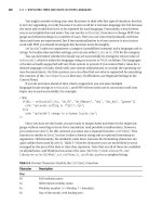
Table 5-1 The Hidden Pen Tools
Icon Tool
Pen
Add Anchor Point
Delete Anchor Point
Convert Anchor Point
Even though you can use a hidden tool to delete and add anchor points,
Illustrator automatically does this as a default when you’re using the Pen
tool. When you move the cursor over an anchor point by using the Pen tool,
a minus icon appears. To delete that anchor point, simply click. Likewise,
when you move the cursor over a part of the path that doesn’t contain
anchor points, a plus icon appears. Simply click to add an anchor point.
If you prefer to use the tools dedicated to adding and deleting anchor points,
choose Edit➪Preferences➪General (Windows) or Illustrator➪Preferences➪
General (Mac); in the Preferences dialog box that appears, select the Disable
Auto Add/Delete check box. Then, when you want to add or delete an anchor
point, select the appropriate tool and click the path.
Adding tools to help make paths
Some Pen tool modifiers are available in the Control panel in Illustrator CS5.
You can take advantage of them for many Pen tool uses, but using keyboard
shortcuts to switch the Pen tool to its various options is probably still faster.
If you’re resistant to contorting your fingers while trying to create a path,
you should appreciate these tools.
To see the Control panel tools, select the Pen tool and start creating a path.
Notice that the Control panel has a series of buttons available, shown in
Figure 5-10.
28_607466-bk03ch05.indd 26728_607466-bk03ch05.indd 267 5/25/10 9:16 AM5/25/10 9:16 AM
268
The Hidden Pen Tools
Figure 5-10:
Control
panel tools
for easy
editing.
Convert Selected
Anchor Points to Smooth
Cut Path at Selected Anchor Points
Connect Selected End Points
Hide Handles for Multiple
Selected Anchor Points
Convert Selected
Anchor Points
to Corner
Remove Selected
Anchor Points
Selected Anchor
Points Coordinates
Show Handles for Multiple
Selected Anchor Points
Using the Eraser tool
The Eraser tool is a tool that all users will love! You can use it to quickly
remove areas of artwork as easily as you erase pixels in Photoshop by strok-
ing with your mouse over any shape or set of shapes.
New paths are automatically created along the edges of the erasure, even
preserving its smoothness, as shown in Figure 5-11.
Figure 5-11:
The Eraser
tool deletes
sections of
a path.
By double-clicking the Eraser tool, you can define the diameter, angle, and
roundness of your eraser (see Figure 5-12). If you’re using a drawing tablet,
you can even set Wacom tablet interaction parameters, such as Pressure
and Tilt.
If you want to erase more than a single selected object, use Isolation mode
to segregate grouped objects for editing. Remember that in order to enter
this mode, you simply double-click a group of items. You can then use the
eraser on all objects in that group at one time without disturbing the rest of
your design.
28_607466-bk03ch05.indd 26828_607466-bk03ch05.indd 268 5/25/10 9:16 AM5/25/10 9:16 AM
Book III
Chapter 5
Using the Pen Tool
and Placing Images
269
Tracing Artwork
Figure 5-12:
Double-click
the Eraser
tool to set
various tool
options.
Tracing Artwork
You can use a template layer to trace an image manually. A template layer is
a locked, dimmed layer you can use to draw over placed images with the Pen
tool, much like you would do with a piece of onion skin paper over the top of
an image.
Creating a template layer
Just follow these steps to create a template layer:
1. Take a scanned image or logo and save it in a format that Illustrator
can import from your image-editing program, such as Photoshop.
Typically, you save the image as an .eps, a .tif, or a native .psd
(Photoshop) file.
2. Choose File➪Place to open the Place dialog box.
3. In the Place dialog box, locate the saved image; then select the
Template check box and click Place.
Note that the Template check box may be in a different location depending
on your platform, but it’s always located at the bottom of the dialog box.
Selecting the Template check box tells Illustrator to lock down the scanned
image on a layer. Essentially, you can’t reposition or edit your image.
After you click Place, a template layer is automatically created for you,
and another layer is waiting for you to create your path. The newly cre-
ated top layer resembles a piece of tracing paper that has been placed
on top of the scanned image.
4. Re-create the image by tracing over it with the Pen tool.
5. When you’re done, turn off the visibility of the placed image by click-
ing the Visibility icon to the left of the template layer.
28_607466-bk03ch05.indd 26928_607466-bk03ch05.indd 269 5/25/10 9:16 AM5/25/10 9:16 AM
270
Tracing Artwork
You now have a path you can use in place of the image, which is useful if
you’re creating an illustration of an image or are digitally re-creating a logo.
For more about layers, check out Chapter 8 of this minibook.
Keep practicing to become more comfortable with clicking and dragging,
flowing with the direction line pointing the way you want the path to be cre-
ated; everything will fall into place.
Using Live Trace
Use the Live Trace feature to automatically trace raster images into vector
paths. This feature works well in many instances but definitely isn’t a “magic
pill” for re-creating images as vectors. For example, a logo with many precise
curves and straight lines isn’t a good candidate for this feature, but a hand-
drawn illustration, clip art, or other drawing works well.
Here are the steps you follow to use Live Trace:
1. Choose File➪Place and place a scan or raster illustration that you
want to convert to vector paths.
Immediately after placing, you see that the Control panel now has addi-
tional buttons available, as shown in Figure 5-13.
Figure 5-13:
Live Trace
Control
panel
features.
Name of file
Resolution of image
File is linked, not embedded
Tracing presets and options
2. You can either click the Live Trace button to automatically trace
based on default settings or, better, click and hold on the Tracing
Options arrow and choose a more appropriate setting.
Choose Tracing Options from the bottom of the Tracing Options drop-
down list to customize settings.
3. After you select settings you’re happy with, you can either use the
Live Paint features to color in the work or click the Expand button in
the Control panel to expand the trace object to vector paths that can
be edited.
See Chapter 9 of this minibook for more information on painting fills and
strokes.
28_607466-bk03ch05.indd 27028_607466-bk03ch05.indd 270 5/25/10 9:16 AM5/25/10 9:16 AM
Book III
Chapter 5
Using the Pen Tool
and Placing Images
271
Using Photoshop Layer Comps
Other Things You Should Know about Placing Images
In the preceding section, you discover how to place an image as a template.
But what if you want to place an image to be used in an illustration file?
Simply choose File➪Place.
Click an image once to see its Link check box. If you keep the check box
selected, the image is linked to the original file, which is helpful if you plan
to reference the file several times in the illustration (it saves file space) or
edit the original and have it update the placed image in Illustrator. This
option is usually selected by people in the prepress industry who want to
have access to the original image file. Just remember to send the image with
the Illustrator file if it’s to be printed or used someplace other than on your
computer.
If you deselect the Link check box, the image is embedded into the
Illustrator file. This option keeps the filing system cleaner but doesn’t leave
much room to edit the original image later. In certain instances, such as
when you want an image to become a symbol (see Chapter 11 of this mini-
book), the image will have to be embedded, but most functions work with
both linked and unlinked files.
Using Photoshop Layer Comps
The Layer Comps feature in Photoshop lets you set the visibility, appearance,
and position of layers. You can take advantage of this useful organizational
tool in other Adobe products. Read more about Photoshop in Book IV.
You can place in Illustrator a .psd (Photoshop) image that has saved Layer
Comps and choose which layer comp set you want visible.
28_607466-bk03ch05.indd 27128_607466-bk03ch05.indd 271 5/25/10 9:16 AM5/25/10 9:16 AM
272
Book III: Illustrator CS5
28_607466-bk03ch05.indd 27228_607466-bk03ch05.indd 272 5/25/10 9:16 AM5/25/10 9:16 AM
Chapter 6: Using Type
in Illustrator
In This Chapter
✓ Introducing the Type tools
✓ Getting to know text areas
✓ Manipulating text along paths and within shapes
✓ Assigning font styles
✓ Discovering the Character, Control, and Paragraph panels
✓ Saving time with text utilities
O
ne of Illustrator’s strongest areas is manipulating text. Whether you’re
using Illustrator to create logos, business cards, or type to be used on
the Web, you have everything you need to create professional-looking text.
In this chapter, you meet the Type tools and discover a few basic (and more
advanced) text-editing tricks that you can take advantage of. You then find
out about other text tools, such as the Character and Paragraph panels.
At the end of this chapter, you get the quick-and-dirty lowdown on the
Illustrator text utilities. These utilities can save you loads of time, so don’t
skip this section.
Working with Type
You can do all sorts of cool things with type, from the simplest tasks of cre-
ating a line of text and dealing with text overflow to more complicated tricks
such as placing text along paths and wrapping text around objects.
Figure 6-1 shows the Type tools with an example of what you can do with
each one. Click and hold the Type tool to see the hidden tools. The differ-
ent tools give you the ability to be creative and also accommodate foreign
languages.
29_607466-bk03ch06.indd 27329_607466-bk03ch06.indd 273 5/25/10 12:09 AM5/25/10 12:09 AM
274
Working with Type
Figure 6-1:
The Type
tools.
Creating text areas
A text area is a region that you define. Text, when inserted in this region, is
constrained within the shape. To create a text area, click and drag with the
Type tool.
As you create and finish typing in a text area, you may want to quickly
click and drag to create a new text area elsewhere on your artboard.
Unfortunately, Illustrator doesn’t allow you to do that. You do have two
options that will help you to create multiple textboxes quickly on your art-
board:
✦ Choose Select➪Deselect and then create another area.
✦ Hold down the Ctrl (Windows) or Ô (Mac) key, and click anywhere on
the artboard outside of the active text area. By clicking, you deactivate
the current text box so that you can click and drag out a new text area.
Creating a line of text
To create a simple line of text, select the Type tool and click the artboard.
A blinking insertion point appears. You can now start typing. With this
method, the line of type goes on forever (even beyond the end of the Scratch
area) until you press Enter (Windows) or Return (Mac) to start a new line of
text. This excess length is fine if you just need short lines of text for callouts
or captions, for example, but it doesn’t work well if you’re creating a label or
anything else that has large amounts of copy.
29_607466-bk03ch06.indd 27429_607466-bk03ch06.indd 274 5/25/10 12:09 AM5/25/10 12:09 AM
Book III
Chapter 6
Using Type
in Illustrator
275
Working with Type
Many new users click and drag an ever-so-small text area that doesn’t allow
room for even one letter. If you accidentally do this, switch to the Selection
tool, delete the active type area, and then click to create a new text insertion
point.
Flowing text into an area
Select the Type tool and then drag on the artboard to create a text area.
The cursor appears in the text area; text you type flows automatically to the
next line when it reaches the edge of the text area. You can also switch to
the Selection tool and adjust the width and height of the text area with the
handles.
Need an exact size for a text area? With the Type tool selected, drag to
create a text area of any size. Then choose Window➪Transform to view the
Transform panel. Type an exact width measurement in the W text field and
an exact height measurement in the H text field.
Dealing with text overflow
Watch out for excess text! If you create a text area that’s too small to hold
all the text you want to put into it, a red plus sign appears in the lower right
corner, as shown in Figure 6-2.
Figure 6-2:
The plus
icon
indicates
that text is
overflowing.
When Illustrator indicates that you have too much text for the text area, you
have several options:
✦ Make the text area larger by switching to the Selection tool and dragging
the handles.
✦ Make the text smaller until you no longer see the overflow indicator.
✦ Thread this text area (link it to another), which is a topic covered later in
this chapter, in the “Threading text into shapes” section.
29_607466-bk03ch06.indd 27529_607466-bk03ch06.indd 275 5/25/10 12:09 AM5/25/10 12:09 AM
276
Working with Type
Creating columns of text with the Area Type tool
The easiest and most practical way to create rows and columns of text is to
use the area type options in Adobe Illustrator. This feature lets you create
rows and columns from any text area. You can have only rows or have only
columns (much like columns of text in a newspaper) or even both.
1. Select the Type tool and drag on the artboard to create a text area.
2. Choose Type➪Area Type Options.
The Area Type Options dialog box appears, as shown in Figure 6-3.
At the end of this section, a list explains all options in the Area Type
Options dialog box.
Figure 6-3:
The Area
Type
Options
dialog box
lets you
create
columns of
text.
3. In the Area Type Options dialog box, enter a width and height in the
Width and Height text fields.
The Width and Height text fields contain the height and width of your
entire text area. In Figure 6-3, 396 pt is in the Width text field and 425
pt is in the Height text field.
4. In the Columns area, enter the number of columns you want to create
in the Number text field, the span distance in the Span text field, and
the gutter space in the Gutter text field.
The span specifies the height of individual rows and the width of individ-
ual columns. The gutter is the space between columns and is automati-
cally set for you, but you can change it to any value you like.
5. Click OK.
29_607466-bk03ch06.indd 27629_607466-bk03ch06.indd 276 5/25/10 12:09 AM5/25/10 12:09 AM
Book III
Chapter 6
Using Type
in Illustrator
277
Working with Type
When you create two or more columns of text from the Area Type Options
dialog box, text flows to the next column when you reach the end of the pre-
vious column, as shown in Figure 6-4.
Figure 6-4:
One column
of text flows
into the
next.
The following list breaks down the other options available in the Area Type
Options dialog box (refer to Figure 6-3):
✦ Width and Height: The present width and height of the entire text area.
✦ Number: The number of rows and/or columns that you want the text
area to contain.
✦ Span: The height of individual rows and the width of individual columns.
✦ Fixed: Determines what happens to the span of rows and columns if you
resize the type area. When this check box is selected, resizing the area
can change the number of rows and columns but not their width. Leave
this option deselected if you want to resize the entire text area and have
the columns automatically resize with it.
✦ Gutter: The empty space between rows or columns.
✦ Inset Spacing: The distance from the edges of the text area.
✦ First Baseline: Where you want the first line of text to appear. The
default Ascent option starts your text normally at the top. If you want to
put in a fixed size, such as 50 points from the top, select Fixed from the
drop-down list, and enter 50 pt in the Min text field.
✦ Text Flow: The direction in which you read the text as it flows to
another row or column. You can choose to have the text flow horizon-
tally (across rows) or vertically (down columns).
29_607466-bk03ch06.indd 27729_607466-bk03ch06.indd 277 5/25/10 12:09 AM5/25/10 12:09 AM
278
Working with Type
Threading text into shapes
Create custom columns of text that are in different shapes and sizes by
threading closed shapes together. This technique works with rectangles,
circles, stars, or any other closed shape and can lead to some creative text
areas.
Follow these steps to thread text into shapes:
1. Create any shape, any size.
For this example, we’ve created a circle.
2. Create another shape (it can be any shape) someplace else on the
page.
3. With the Selection tool, select one shape and Shift-click the other to
make just those two shapes active.
4. Choose Type➪Threaded Text➪Create.
A threading line appears, as shown in Figure 6-5, indicating the direction
of the threaded text.
Figure 6-5:
Threaded
text areas
flow from
one area to
another.
5. Select the Type tool, click the top of the first shape to start the thread-
ing, and start typing.
Continue typing until the text flows over into the other shape.
29_607466-bk03ch06.indd 27829_607466-bk03ch06.indd 278 5/25/10 12:09 AM5/25/10 12:09 AM