DISTRIBUTED SYSTEMS principles and paradigms Second Edition phần 8 docx
Bạn đang xem bản rút gọn của tài liệu. Xem và tải ngay bản đầy đủ của tài liệu tại đây (1.33 MB, 71 trang )
SEC. 10.7
FAULT TOLERANCE
479
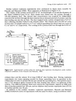
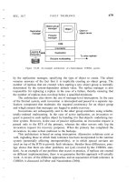
Figure 10-20. An example architecture of a fault-tolerant CORBA system.
by the replication manager, specifying the type of object to create. The client
remains unaware of the fact that it is implicitly creating an object group. The
number of replicas that are created when starting a new object group is normally
determined by the system-dependent default value. The replica manager is also
responsible for replacing a replica in the case of a failure, thereby ensuring that
the number of replicas does not drop below a specified minimum.
The architecture also shows the use of message-level interceptors. In the case
of the Eternal system, each invocation is intercepted and passed to a separate rep-
lication component that maintains the required consistency for an object group
and which ensures that messages are logged to enable recovery.
Invocations are subsequently sent to the other group members using reliable,
totally-ordered multicasting. In the case of active replication, an invocation re-
quest is passed to each replica object by handing it to that object's underlying run-
time system. However, in the case of passive replication, an invocation request is
passed only to the RTS of the primary, whereas the other servers only log the
invocation request for recovery purposes. When the primary has completed the
invocation, its state is then multicast to the backups.
This architecture is based on using interceptors. Alternative solutions exist as
well, including those in which fault tolerance has been incorporated in the runtime
system (potentially affecting interoperability), or in which special services are
used on top of the RTS to provide fault tolerance. Besides these differences, prac-
tice shows that there are other problems not (yet) covered by the CORBA stan-
dard. As an example of one problem that occurs in practice, if replicas are created
on different implementations, there is no guarantee that this approach will actually
work. A review of the different approaches and an assessment of fault tolerance in
CORBA is discussed in Felber and Narasimhan (2004).
480
DISTRIBUTED OBJECT-BASED SYSTEMS
CHAP. ]0
10.7.2 Example: Fault-Tolerant Java
Considering the popularity of Java as a language and platform for developing
distributed applications, some effort has also been into adding fault tolerance to
the Java runtime system. An interesting approach is to ensure that the Java virtual
machine can be used for active replication.
Active replication essentially dictates that the replica servers execute as deter-
ministic finite-state machines (Schneider, 1990). An excellent candidate in Java
to fulfill this role is the Java Virtual Machine (JVM). Unfortunately, the JVM is
not deterministic at all. There are various causes for nondeterministic behavior,
identified independently by Napper et al. (2003) and Friedman and Kama (2003):
1. JVM can execute native code, that is, code that is external to the
JVM and provided to the latter through an interface. The JVM treats
native code like a black box: it sees only the interface, but has no
clue about the (potentially nondeterministic) behavior that a call
causes. Therefore, in order to use the
NM
for active replication, it is
necessary to make sure that native code behaves in a deterministic
way.
2. Input data may be subject to non determinism. For example, a shared
variable that can be manipulated by multiple threads may change for
different instances of the JVM as
10nQ
as threads are allowed to
operate concurrently. To control this behavior, shared data should at
the very least be protected through locks. As it turned out, the Java
runtime environment did not always adhere to this rule, despite its
support for multithreading.
3. In the presence of failures, different JVMs will produce different out-
put revealing that the machines have been replicated. This difference
may cause problems when the JVMs need to brought back into the
same state. Matters are simplified if one can assume that all output is
idempotent (i.e., can simply be replayed), or is testable so that one
can check whether output was produced before a crash or not. Note
that this assumption is necessary in order to allow a replica server to
decide whether or not it should re-execute an operation.
Practice shows that turning the JVM into a deterministic finite-state machine
is by no means trivial. One problem that needs to be solved is the fact that replica
servers may crash. One possible organization is to let the servers run according to
a primary-backup scheme. In such a scheme, one server coordinates all actions
that need to be performed, and from time to time instructs the backup to do the
same. Careful coordination between primary and backup is required, of course.
SEC. 10.7
FAULT TOLERANCE
481
Note that despite the fact that replica servers are organized in a primary-
backup setting, we are still dealing with active replication: the replicas are kept up
to date by letting each of them execute the same operations in the same order.
However, to ensure the same nondeterministic behavior by all of the servers, the
behavior of one server is taken as the one to follow.
In this setting, the approach followed by Friedman and Kama (2003) is to let
the primary first execute the instructions of what is called a frame. A frame con-
sists of the execution of several context switches and ends either because all
threads are blocking for I/O to complete, or after a predefined number of context
switches has taken place. Whenever a thread issues an I/O operation, the thread is
blocked by the JVM put on hold. When a frame starts, the primary lets all I/O re-
quests proceed, one after the other, and the results are sent to the other replicas. In
this way, at least deterministic behavior with respect to I/O operations is enforced.
The problem with this scheme is easily seen: the primary is always ahead of
the other replicas. There are two situations we need to consider. First, if a replica
server other than the primary crashes, no real harm is done except that the degree
of fault tolerance drops. On the other hand, when the primary crashes, we may
find ourselves in a situation that data (or rather, operations) are lost.
To minimize the damage, the primary works on a per-frame basis. That is, it
sends update information to the other replicas only after completion of its current
frame. The effect of this approach is that when the primary is working on the k-th
frame, that the other replica servers have all the information needed to process the
frame preceding the k-th one. The damage can be limited by making frames small,
at the price of more communication between the primary and the backups.
10.8 SECURITY
Obviously, security plays an important role in any distributed system and ob-
ject-based ones are no exception. When considering most object-based distributed
systems, the fact that distributed objects are remote objects immediately leads to a
situation in which security architectures for distributed systems are very similar.
In essence, each object is protected through standard authentication and authoriza-
tion mechanisms, like the ones we discussed in Chap. 9.
To make clear how security can fit in specifically in an object-based distrib-
uted system, we shall discuss the security architecture for the Globe system. As
we mentioned before, Globe supports truly distributed objects in which the state
of a single object can be spread and replicated across multiple machines. Remote
objects are just a special case of Globe objects. Therefore, by considering the
Globe security architecture, we can also see how its approach can be equally
applied to more traditional object-based distributed systems. After discussing
Globe, we briefly take a look at security in traditional object-based systems.
482
DISTRIBUTED OBJECT-BASED SYSTEMS
CHAP. 10
10.8.1 Example: Globe
As we said, Globe is one of the few distributed object-based systems in which
an object's state can be physically distributed and replicated across multiple ma-
chines. This approach also introduces specific security problems, which have led
to an architecture as described in Popescu et a1.(2002).
Overview
When we consider the general case of invoking a method on a remote object,
there are at least two issues that are important from a security perspective: (1) is
the caller invoking the correct object and (2) is the caller allowed to invoke that
method. We refer to these two issues as secure object binding and secure meth-
od invocation, respectively. The former has everything to do with authentication,
whereas the latter involves authorization. For Globe and other systems that sup-
port either replication or moving objects around, we have an additional problem,
namely that of platform security. This kind of security comprises two issues.
First, how can the platform to which a (local) object is copied be protected against
any malicious code contained in the object, and secondly, how can the object be
protected against a malicious replica server.
Being able to copy objects to other hosts also brings up another problem.
Because the object server that is hosting a copy of an object need not always be
fully trusted, there must be a mechanism that prevents that every replica server
hosting an object from being allowed to also execute any of an object's methods.
For example, an object's owner may want to restrict the execution of update
methods to a small group of replica servers, whereas methods that only read the
state of an object may be executed by any authenticated server. Enforcing such
policies can be done through reverse access control, which we discuss in more
detail below.
There are several mechanisms deployed in Globe to establish security. First,
every Globe object has an associated public/private key pair, referred to as the ob-
ject key. The basic idea is that anyone who has knowledge about an object's
private key can set the access policies for users and servers. In addition, every
replica has an associated replica key, which is also constructed as a public/private
key pair. This key pair is generated by the object server currently hosting the spe-
cific replica. As we will see, the replica key is used to make sure that a specific
replica is part of a given distributed shared object. Finally, each user is also
assumed to have a unique public/private key pair, known as the user key.
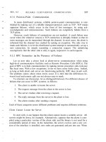
These keys are used to set the various access rights in the form of certificates.
Certificates are handed out per object. There are three types, as shown in Fig. 10-
21. A user certificate is associated with a specific user and specifies exactly
which methods that user is allowed to invoke. To this end, the certificate contains
SEC. 10.8
a bit string
U
with the same length as the number of methods available for the ob-
ject. U
(i]
=
1 if and only if the user is allowed to invoke method Mi' Likewise,
there is also a replica certificate that specifies, for a given replica server, which
methods it is allowed to execute. It also has an associated bit string R, where
R
[i]
=
i if and only if the server is allowed to execute method
Mi'
Figure 10-21. Certificates in Globe: (a) a user certificate, (b) a replica certifi-
cate, (c) an administrative certificate.
For example, the user certificate in Fig. 10-21(a) tells that Alice (who can be
identified through her public key
xu;»
has the right to invoke methods
M
2,
M
5,
M
6, and
M
7 (note that we start indexing
U
at 0). Likewise, the replica certificate
states that the server owning
Kkepl
is allowed to execute methods
M
0,
M
1,
M
5,
M
6
,
andM
7
·
An administrative certificate can be used by any authorized entity to issue
user and replica certificates. In the case, the Rand
U
bit strings specify for which
methods and which entities a certificate can be created. Moreover, there is bit
indicating whether an administrative entity can delegate (part of) its rights to
someone else. Note that when Bob in his role as administrator creates a user certi-
ficate for Alice, he will sign that certificate with his own signature, not that of the
object. As a consequence, Alice's certificate will need to be traced back to Bob's
administrative certificate, and eventually to an administrative certificate signed
with the object's private key.
Administrative certificates come in handy when considering that some Globe
objects may be massively replicated. For example, an object's owner may want to
manage only a relatively small set of permanent replicas, but delegate the creation
of server-initiated replicas to the servers hosting those permanent replicas. In that
case, the owner may decide to allow a permanent replica to install other replicas
for read-only access by all users. Whenever Alice wants to invoke a read-only
method, she will succeed (provided she is authorized). However, when wanting to
invoke an update method, she will have to contact one of the permanent replicas,
as none of the other replica servers is allowed to execute such methods.
As we explained, the binding process in Globe requires that an object identi-
fier (OlD) is resolved to a contact address. In principle, any system that supports
SECURITY
483
484
DISTRIBUTED OBJECT· BASED SYSTEMS
CHAP. 10
flat names can be used for this purpose. To securely associate an object's public
key to its DID, we simply compute the DID as a 160-bit secure hash of the public
key. In this way, anyone can verify whether a given public key belongs to a given
DID. These identifier are also known as self-certifying names, a concept
pioneered in the Secure File System (Mazieres et aI., 1999), which we will discuss
in Chap. I
J.
We can also check .whether a replica R belongs to an object O. In that case,
we merely need to inspect the replica certificate for R, and check who issued it.
The signer may be an entity with administrative rights, in which case we need to
inspect its administrative certificate. The bottom line is that we can construct a
chain of certificates of which the last one is signed using the object's private key.
In that case, we know that R is part of O.
To mutually protect objects and hosts against each other, techniques for
mobile code, as described in Chap. 9 are deployed. Detecting that objects have
been tampered with can be done with special auditing techniques which we will
describe in Chap.
J
2.
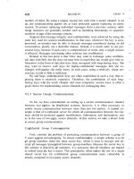
Secure Method Invocation
Let us now look into the details of securely invoking a method of a Globe ob-
ject. The complete path from requesting an invocation to actually executing the
operation at a replica is sketched in Fig. 10-22. A total of 13 steps need to be exe-
cuted in sequence, as shown in the figure and described in the following text.
Figure 10-22. Secure method invocation in Globe.
SEC. 10.8
SECURITY
485
-l
First, an application issues a invocation request by locally calling the
associatedmethod, just.like calling a procedure in an RPC.
2. The control subobject checks the user permissions with the informa-
tion stored in the local security object. In this case, the security ob-
ject should have a valid user certificate.
3. The request is marshaled and passed on.
4. The replication subobject requests the middleware to set up a secure
channel to a suitable replica.
5. The security object first initiates a replica lookup. To achieve this
goal, it could use any naming service that can look up replicas that
have been specified to be able to execute certain methods. The Globe
location service has been modified to handle such lookups (Ballin-
tijn, 2003).
6. Once a suitable replica has been found, the security subobject can set
up a secure channel with its peer, after which control is returned to
the replication subobject. Note that part of this establishment re-
quires that the replica proves it is allowed to carry out the requested
invocation.
7. The request is now passed on to the communication subobject.
8. The subobject encrypts and signs the request so that it can pass
through the channel.
9. After its receipt, the request is decrypted and authenticated.
10. The request is then simply passed on to the server-side replication
subobject.
11. Authorization takes place: in this case the user certificate from the
client-side stub has been passed to the replica so that we can verify
that the request can indeed be carried out.
12. The request is then unmarshaled.
13. Finally, the operation can be executed.
Although this may seem to be a relatively large number of steps, the example
shows how a secure method invocation can be broken down into small units, each
unit being necessary to ensure that an authenticated client can carry out an author-
ized invocation at an authenticated replica. Virtually all object-based distributed
systems follow these steps. The difference with Globe is that a suitable replica
needs to be located, and that this replica needs to prove it may execute the method
call. We leave such a proof as an exercise to the reader.
486
DISTRIBUTED OBJECT-BASED SYSTEMS
CHAP. 10
10.8.2 Security for Remote Objects
When using remote objects we often see that the object reference itself is im-
plemented as a complete client-side stub, containing all the information that is
needed to access the remote object. In its simplest form, the reference contains the
exact contact address for the object and uses a standard marshaling and communi-
cation protocol to ship an invocation to the remote object.
However, in systems such as Java, the client-side stub (called a proxy) can be
virtually anything. The basic idea is that the developer of a remote object also
develops the proxy and subsequently registers the proxy with a directory service.
When a client is looking for the object, it will eventually contact the directory ser-
vice, retrieve the proxy, and install it. There are obviously some serious problems
with this approach.
First, if the directory service is hijacked, then an attacker may be able to re-
turn a bogus proxy to the client. In effect, such a proxy may be able to comprom-
ise all communication between the client and the server hosting the remote object,
damaging both of them.
Second, the client has no way to authenticate the server: it only has the proxy
and all communication with the server necessarily goes through that proxy. This
may be an undesirable situation, especially because the client now simply needs to
trust the proxy that it will do its work correctly.
Likewise, it may be more difficult for the server to authenticate the client.
Authentication may be necessary when sensitive information is sent to the client.
Also, because client authentication is now tied to the proxy, we may also have the
situation that an attacker is spoofing a client causing damage to the remote object.
Li et al. (2004b) describe a general security architecture that can be used to
make remote object Invocations safer. In their model, they assume that proxies are
indeed provided by the developer of a remote object and registered with a direc-
tory service. This approach is followed in Java RMI, but also Jini (Sun Microsys-
terns, 2005).
The first problem to solve is to authenticate a remote object. In their solution,
Li and Mitchell propose a two-step approach. First, the proxy which is down-
loaded from a directory service is signed by the remote object allowing the client
to verify its origin. The proxy; in tum, will authenticate the object using TLS with
server authentication, as we discussed in Chap. 9. Note that it is the object
developer's task to make sure that the proxy indeed properly authenticates the ob-
ject. The client will have to rely on this behavior, but because it is capable of
authenticating the proxy, relying on object authentication is at the same level as
trusting the remote object to behave decently.
To authenticate the client, a separate authenticator is used. When a client is
looking up the remote object, it will be directed to this authenticator from which it
downloads an authentication proxy. This is a special proxy that offers an inter-
face by which the client can have itself authenticated by the remote object. If this
SEC. 10.8
SECURITY
487
authentication succeeds. then the remote object (or actually, its object server) will
pass on the actual proxy to the client. Note that this approach allows for authenti-
cation independent of the protocol used by the actual proxy, which is considered
an important adyantage.
Another important advantage of separating client authentication is that it is
now possible to pass dedicated proxies to clients. For example, certain clients may
be allowed to request only execution of read-only methods. In such a case, after
authentication has taken place, the client will be handed a proxy that offers only
such methods, and no other. More refined access control can easily be envisaged.
10.9 SUMMARY
Most object-based distributed systems use a remote-object model in which an
object is hosted by server that allows remote clients to do method invocations. In
many cases, these objects will be constructed at runtime, effectively meaning that
their state, and possibly also code is loaded into an object server when a client
does a remote invocation. Globe is a system in which truly distributed shared ob-
jects are supported. In this case, an object's state may be physically distributed
and replicated across multiple machines.
To support distributed objects, it is important to separate functionality from
extra-functional properties such as fault tolerance or scalability. To this end,
advanced object servers have been developed for hosting objects. An object server
provides many services to basic objects, including facilities for storing objects, or
to ensure serialization of incoming requests. Another important role is providing
the illusion to the outside world that a collection of data and procedures operating
on that data correspond to the concept of an object. This role is implemented by
means of object adapters.
When it comes to communication, the prevalent way to invoke an object is by
means of a remote method invocation (RMI), which is very similar to an RPC. An
important difference is that distributed objects generally provide a systemwide ob-
ject reference, allowing a process to access an object from any machine. Global
object reference solve many of the parameter-passing problems that hinder access
transparency of RPCs.
There are many different ways in which these object references can be imple-
mented, ranging from simple passive data structures describing precisely where a
remote object can be contacted, to portable code that need simply be invoked by a
client. The latter approach is now commonly adopted for Java RMI.
There are no special measures in most systems to handle object synchroniza-
tion. An important exception is the way that synchronized Java methods are
treated: the synchronization takes place only between clients running on the same
machine. Clients running on different machines need to take special synchroniza-
tion measures. These measures are not part of the Java language.
488
DISTRffiUTED OBJECT-BASED SYSTEMS
CHAP. 10
Entry consistency is an obvious consistency model for distributed objects and
is (often implicitly) supported in many systems. It is obvious as we can naturally
associate a separate lock for each object. One of the problems resulting from
replicating objects are replicated invocations. This problem is more evident be-
cause objects tend to be treated as black boxes.
Fault tolerance in distributed object-based systems very much follows the ap-
proaches used for other distributed systems. One exception is formed by tryingto
make the Java virtual machine fault tolerant by letting it operate as a deterministic
finite state machine. Then, by replicating a number of these machines, we obtain a
natural way for providing fault tolerance.
Security for distributed objects evolves around the idea of supporting secure
method invocation. A comprehensive example that generalizes these invocations
to replicated objects is Globe. As it turns out, it is possible to cleanly separate pol-
icies from mechanisms. This is true for authentication as well as authorization.
Special attention needs to be paid to systems in which the client is required to
download a proxy from a directory service, as is commonly the case for Java.
PROBLEMS
1. We made a distinction between remote objects and distributed objects. What is the
difference?
2. Why is it useful to define the interfaces of an object in an Interface Definition
Language?
3. Some implementations of distributed-object middleware systems are entirely based on
dynamic method invocations. Even static invocations are compiled to dynamic ones.
What is the benefit of this approach?
4. Outline a simple protocol that implements at-most-once semantics for an object invo-
cation. .
5. Should the client and server-side objects for asynchronous method invocation be per-
sistent?
6. In the text, we mentioned that an implementation of CORBA's asynchronous method
invocation do not affect the server-side implementation of an object. Explain why this
is the case.
7. Give an example in which the (inadvertent) use of callback mechanisms can easily
lead to an unwanted situation.
8. Is it possible for an object to have more than one servant?
9. Is it possible to have system-specific implementations of CORBA object references
while still being able to exchange references with other CORBA-based systems?
CHAP. 10
PROBLEMS
489
10.
How can we authenticate the contact addresses returned by a lookup service for secure
Globe objects?
11.
What is the key difference between object references in CORBA and those in Globe?
12.
Consider Globe. Outline a simple protocol by which a secure channel is set up be-
tween a user proxy (which has access to the Alice's private key) and a replica that we
know for certain can execute a given method.
13.
Give an example implementation of an object reference that allows a client to bind to
a transient remote object.
14.
Java and other languages support exceptions, which are raised when an error occurs.
How would you implement exceptions in RPCs and RMls?
15.
How would you incorporate persistent asynchronous communication into a model of
communication based on RMls to remote objects?
16. Consider a distributed object-based system that supports object replication, in which
all method invocations are totally ordered. Also, assume that an object invocation is
atomic (e.g., because every object is automatically locked when invoked). Does such a
system provide entry consistency? What about sequential consistency'?
17.
Describe a receiver-based scheme for dealing with replicated invocations, as men-
tioned in the text.
DISTRIBUTED FILE SYSTEMS
Considering that sharing data is fundamental to distributed systems, it is not
surprising that distributed file systems form the basis for many distributed applica-
tions. Distributed file systems allow multiple processes to share data over long
periods of time in a secure and reliable way. As such, they have been used as the
basic layer for distributed systems and applications. In this chapter, we consider
distributed file systems as a paradigm for general-purpose distributed systems.
11.1 ARCHITECTURE
We start our discussion on distributed file systems by looking at how they are
generally organized. Most systems are built following a traditional client-server
architecture, but fully decentralized solutions exist as well. In the following, we
will take a look at both kinds of organizations.
11.1.1 Client-Server Architectures
Many distributed files systems are organized along the lines of client-server
architectures. with Sun Microsystem's Network File System (NFS) being one of
the most widely-deployed ones for UNIX-based systems. We will take NFS as a
canonical example for server-based distributed tile systems throughout this chap-
ter.
In
particular, we concentrate on NFSv3, the widely-used third version of NFS
491
492
DISTRIBUTED FILE SYSTEMS
CHAP. 11
(Callaghan, 2000) and NFSv4, the most recent, fourth version (Shepler et al.,
2003). We will discuss the differences between them as well.
The basic idea behind NFS is that each file server. provides a standardized
view of its local file system. In other words, it should not matter how that local
file system is implemented; each NFS server supports the same model. This ap-
proach has been adopted for other distributed files systems as well. NFS comes
with a communication protocol that allows clients to access the files stored on a
server, thus allowing a heterogeneous collection of processes, possibly running on
different operating systems and machines, to share a common file system.
The model underlying NFS and similar systems is that of a remote file ser-
vice. In this model, clients are offered transparent access to a file system that is
managed by a remote server. However, clients are normally unaware of the actual
location of files. Instead, they are offered an interface to a file system that is simi-
lar to the interface offered by a conventional local file system. In particular, the
client is offered only an interface containing various file operations, but the server
is responsible for implementing those operations. This model is therefore also
referred to as the remote access model. It is shown in Fig. 11-I(a).
Figure 11-1. (a) The remote access model. (b) The upload/download model.
In contrast, in the upload/download model a client accesses a file locally
after having downloaded it from the server, as shown in Fig. 11-l(b).When the
client is finished with the file, it is uploaded back to the server again so that it can
be used by another client. The Internet's FTP service can be used this way when a
client downloads a complete file, modifies it, and then puts it back.
NFS has been implemented for a large number of different operating systems,
although the UNIX-based versions are predominant. For virtually all modern UNIX
systems, NFS is generally implemented following the layered architecture shown
in Fig. 11-2.
A client accesses the file system using the system calls provided by its local
operating system. However, the local UNIX file system interface is replaced by an
SEC. 11.1
ARCHITECTURE
493
Figure 11-2. The basicNf'S architecture for UNIX systems.
interface to the Virtual File System (VFS), which by now is a de facto standard
for interfacing to different (distributed) file systems (Kleiman, 1986). Virtually
all modem operating systems provide VFS, and not doing so more or less forces
developers to largely reimplement huge of an operating system when adopting a
new file-system structure. With NFS, operations on the VFS interface are either
passed to a local file system, or passed to a separate component known as the
~FS client, which takes care of handling access to files stored at a remote server.
In :N'FS,all client-server communication is done through RPCs. The NFS client
•
implements the NFS file system operations as RPCs to the server. Note that the
operations offered by the VFS interface can be different from those offered by the
NFS client. The whole idea of the VFS is to hide the differences between various
file systems.
On the server side, we see a similar organization. The NFS server is responsi-
ble for handling incoming client requests. The RPC stub unmarshals requests and
the NFS server converts them to regular VFS file operations that are subsequently
passed to the VFS layer. Again, the VFS is responsible for implementing a local
file system in which the actual files are stored.
An important advantage of this scheme is that NFS is largely independent of
local file systems. In principle, it really does not matter whether the operating sys-
tem at the client or server implements a UNIX file system, a Windows 2000 file
system, or even an old MS-DOS file system. The only important issue is that these
file systems are compliant with the file system model offered by NFS. For ex-
ample, MS-DOS with its short file names cannot be used to implement an NFS
server in a fully transparent way.
494
DISTRIBUTED ALE SYSTEMS
CHAP. II
File System Model
The file system model offered by NFS is almost the same as the one offered
by UNIX-based systems. Files are treated as uninterpreted sequences of bytes.
They are hierarchically organized into a naming graph in which nodes represent
directories and files. NFS also supports hard links as well as symbolic links, like
any UNIX file system. Files are named, but are otherwise accessed by means of a
UNIX-like file handle. which we discuss in detail below. In other words, to access
a file, a client must first look up its name in a naming service and obtain the asso-
ciated file handle. Furthermore, each file has a number of attributes whose values
can be looked up and changed. We return to file naming in detail later in this
chapter.
Fig. 11-3 shows the general file operations supported by NFS versions 3 and
4, respectively. The create operation is used to create a file, but has somewhat dif-
ferent meanings in NFSv3 and NFSv4. In version 3, the operation is used for
creating regular files. Special files are created using separate operations. The link
operation is used to create hard links. Symlink is used to create symbolic links.
Mkdiris used to create subdirectories. Special files, such as device files, sockets,
and named pipes are created by means of the mknod operation.
This situation is changed completely in NFSv4, where create is used for
creating nonregular files, which include symbolic links, directories, and special
files. Hard links are still created using a separate link operation, but regular files
are created by means of the open operation, which is new to NFS and is a major
deviation from the approach to file handling in older versions. Up until version 4,
NFS was designed to allow its file servers to be stateless. For reasons we discuss
later in this chapter, this design criterion has been abandoned in NFSv4, in which
it is assumed that servers will generally maintain state between operations on the
same file.
The operation rename is used to change the name of an existing file the same
as in UNIX.
Files are deleted by means of the remove operation. In version 4, this opera-
tion is used to remove any kind of file. In previous versions, a separate rmdir oper-
ation was needed to remove a subdirectory. A file is removed by its name and has
the effect that the number of hard links to it is decreased by one. If the number of
links drops to zero, the file may be destroyed.
Version 4 allows clients to open and close (regular) files. Opening a nonexist-
ing file has the side effect that a new file is created. To open a file, a client pro-
vides a name, along with various values for attributes. For example, a client may
specify that a file should be opened for write access. After a file has been success-
fully opened, a client can access that file by means of its file handle. That handle
is also used to close the file, by which the client tells the server that it will no
longer need to have access to the file. The server, in tum, can release any state it
maintained to provide that client access to the file.
SEC. 11.1
ARCHITECTURE
495
Figure 11-3. An incomplete list of file system operations supported by NFS.
The lookup operation is used to look up a file handle for a given path name. In
NFSv3, the lookup operation will not resolve a name beyond a mount point.
(Recall from Chap. 5 that a mount point is a directory that essentially represents a
link to a subdirectory in a foreign name space.) For example, assume that the
name /remote/vu refers to a mount point in a naming graph. When resolving the
name /remote/vu/mbox, the lookup operation in NFSv3 will return the file handle
for the mount point Iremotelvu along with the remainder of the path name (i.e.,
mboxy. The client is then required to explicitly mount the file system that is need-
ed to complete the name lookup. A file system in this context is the collection of
files, attributes, directories, and data blocks that are jointly implemented as a logi-
cal block device (Tanenbaum and Woodhull, 2006).
In version 4, matters have been simplified. In this case, lookup will attempt to
resolve the entire name, even if this means crossing mount points. Note that this
approach is possible only if a file system has already been mounted at mount
points. The client is able to detect that a mount point has been crossed by inspect-
ing the file system identifier that is later returned when the lookup completes.
There is a separate operation readdir to read the entries in a directory. This
operation returns a list of (name, file handle) pairs along with attribute values that
496
DISTRIBUTED FILE SYSTEMS
CHAP. 11
the client requested. The client can also specify how many entries should be re-
turned. The operation returns an offset that can be used in a subsequent call to
readdir in order to read the next series of entries.
Operation readlink is used to read the data associated with a symbolic link.
Normally, this data corresponds to a path name that can be subsequently looked
up. Note that the lookup operation cannot handle symbolic links. Instead, when a
symbolic link is reached, name resolution stops and the client is required to first
call readlink to find out where name resolution should continue.
Files have various attributes associated with them. Again, there are important
differences between NFS version 3 and 4, which we discuss in detail later. Typi-
cal attributes include the type of the file (telling whether we are dealing with a di-
rectory, a symbolic link, a special file, etc.), the file length, the identifier of the
file system that contains the file, and the last time the file was modified. File attri-
butes can be read and set using the operations getattr and setattr, respectively.
Finally, there are operations for reading data from a file, and writing data to a
file. Reading data by means of the operation read is completely straightforward.
The client specifies the offset and the number of bytes to be read. The client is re-
turned the actual number of bytes that have been read, along with additional status
information (e.g., whether the end-of-file has been reached).
Writing data to a file is done using the write operation. The client again speci-
fies the position in the file where writing should start, the number of bytes to be
written, and the data. In addition, it can instruct the server to ensure that all data
are to be written to stable storage (we discussed stable storage in Chap. 8). N""FS
servers are required to support storage devices that can survive power supply
failures, operating system failures, and hardware failures.
11.1.2 Cluster-Based Distributed File Systems
NFS is a typical example for many distributed file systems, which are gener-
ally organized according to a traditional client-server architecture. This architec-
ture is often enhanced for server clusters with a few differences.
Considering that server clusters are often used for parallel applications, it is
not surprising that their associated file systems are adjusted accordingly. One
well-known technique is to deploy file-striping techniques, by which a single file
is distributed across multiple servers. The basic idea is simple: by distributing a
large file across multiple servers, it becomes possible to fetch different parts in
parallel. Of course, such an organization works well only if the application is or-
ganized in such a way that parallel data access makes sense. This generally re-
quires that the data as stored in the file have a very regular structure, for example,
a (dense) matrix.
For general-purpose applications, or those with irregular or many different .
types of data structures, file striping may not be an effective tool. In those cases. it
is often more convenient to partition the file system as a whole and simply store
SEC. 11.1
ARCHITECTURE
497
different files on different servers, but not to partition a single file across multiple
servers. The difference between these two approaches is shown in Fig. 11-4.
More interesting are the cases of organizing a distributed file system for very
large data centers such as those used by companies like Amazon and Google.
These companies offer services to Web clients resulting in reads and updates to a
massive number of files distributed across literally tens of thousands of computers
[see also Barroso et al. (2003)]. In such environments, the traditional assumptions
concerning distributed file systems no longer hold. For example, we can expect
that at any single moment there will be a computer malfunctioning.
To address these problems, Google, for example, has developed its own Goo-
gle file system (GFS), of which the design is described in Ghemawat et al.
(2003). Google files tend to be very large, commonly ranging up to multiple giga-
bytes, where each one contains lots of smaller objects. Moreover, updates to files
usually take place by appending data rather than overwriting parts of a file. These
observations, along with the fact that server failures are the norm rather than the
exception, lead to constructing clusters of servers as shown in Fig. 11-5.
,-,
,-,
Figure 11-4. The difference between (a) distributing whole files across several
servers and (b) striping files for parallel access.
Figure 11-S. The organization of a Google cluster of servers.
Each GFS cluster consists of a single master along with multiple chunk ser-
vers. Each GFS file is divided into chunks of 64 Mbyte each, after which these
498
DISTRIBUTED FILE SYSTEMS
CHAP. 11
chunks are distributed across what are called chunk servers. An important obser-
vation is that a GFS master is contacted only for metadata information. In particu-
lar, a GFS client passes a file name and chunk index to the master, expecting a
contact address for the chunk. The contact address contains all the information to
access the correct chunk server to obtain the required file chunk.
To this end, the GFS master essentially maintains a name space, along with a
mapping from file name to chunks. Each chunk has an associated identifier that
will allow a chunk server to lookup it up. In addition, the master keeps track of
where a chunk is located. Chunks are replicated to handle failures, but no more
than that. An interesting feature is that the GFS master does not attempt to keep
an accurate account of chunk locations. Instead, it occasionally contacts the chunk
servers to see which chunks they have stored.
The advantage of this scheme is simplicity. Note that the master is in control
of allocating chunks to chunk servers. In addition, the chunk servers keep an
account of what they have stored. As a consequence, once the master has obtained
chunk locations, it has an accurate picture of where data is stored. However, mat-
ters would become complicated if this view had to be consistent all the time. For
example, every time a chunk server crashes or when a server is added, the master
would need to be informed. Instead, it is much simpler to refresh its information
from the current set of chunk servers through polling. GFS clients simply get to
know which chunk servers the master believes is storing the requested data.
Because chunks are replicated anyway, there is a high probability that a chunk is
available on at least one of the chunk servers.
Why does this scheme scale? An important design issue is that the master is
largely in control, but that it does not form a bottleneck due to all the work it
needs to do. Two important types of measures have been taken to accommodate
scalability.
First, and by far the most important one, is that the bulk of the actual work is
done by chunk servers. When a client needs to access data, it contacts the master
to find out which chunk servers hold that data. After that, it communicates only
with the chunk servers. Chunks are replicated according to a primary-backup
scheme. When the client is performing an update operation, it contacts the nearest
chunk server holding that data, and pushes its updates to that server. This server
will push the update to the next closest one holding the data, and so on. Once all
updates have been propagated, the client will contact the primary chunk server,
who will then assign a sequence number to the update operation and pass it on to
the backups. Meanwhile, the master is kept out of the loop.
Second, the (hierarchical) name space for files is implemented using a simple
single-level table, in which path names are mapped to metadata (such as the
equivalent of inodes in traditional file systems). Moreover, this entire table is kept
in main memory, along with the mapping of files to chunks. Updates on these data
are logged to persistent storage. When the log becomes too large, a checkpoint is
made by which the main-memory data is stored in such a way that it can be
SEC. 11.1
ARCHITECTURE
499
immediately mapped back into main memory. As a consequence, the intensity of
I/O of a GFS master is strongly reduced.
This organization allows a single master to control a few hundred chunk ser-
vers, which is a considerable size for a single cluster. By subsequently organizing
a service such as Google into smaller services that are mapped onto clusters, it is
not hard to imagine that a huge collection of clusters can be made to work
together.
11.1.3 Symmetric Architectures
Of course, fully symmetric organizations that are based on peer-to-peer tech-
nology also exist. All current proposals use a DHT-based system for distributing
data, combined with a key-based lookup mechanism. An important difference is
whether they build a file system on top of a distributed storage layer, or whether
whole files are stored on the participating nodes.
An example of the first type of file system is Ivy, a distributed file system that
is built using a Chord DHT-based system. Ivy is described in Muthitacharoen et
al. (2002). Their system essentially consists of three separate layers as shown in
Fig. 11-6. The lowest layer is formed by a Chord system providing basic decen-
tralized lookup facilities. In the middle is a fully distributed block-oriented stor-
age layer. Finally, on top there is a layer implementing an NFS-like file system.
Figure 11-6. The organization of the Ivy distributed file system.
Data storage in Ivy is realized by a Chord-based, block-oriented distributed
storage system called DHash (Dabek et al., 2001). In essence, DHash is quite
simple. It only knows about data blocks, each block typically having a size of 8
KB. Ivy uses two kinds of data blocks. A content-hash block has an associated
key, which is computed as the secure hash of the block's content. In this way,
whenever a block is looked up, a client can immediately verify whether the cor-
rect block has been looked up, or that another or corrupted version is returned.
500
DISTRIBUTED FILE SYSTEMS
CHAP. II
Furthermore, Ivy also makes use of public-key blocks, which are blocks having a
public key as lookup key, and whose content has been signed with the associated
private key.
To increase availability, DHash replicates every block
B
to the
k
immediate
successors of the server responsible for storing
B.
In addition, looked up blocks
are also cached along the route that the lookup request followed.
Files are implemented as a separate data structure on top of DHash. To
achieve this goal, each user maintains a log of operations it carries out on files.
For simplicity, we assume that there is only a single user per node so that each
node will have its own log. A log is a linked list of immutable records, where each
record contains all the information related to an operation on the Ivy file system.
Each node appends records only to its own, local, log. Only a log's head is mut-
able, and points to the most recently appended record. Each record is stored in a
separate content-hash block, whereas a log's head is kept in a public-key block.
There are different types of records, roughly corresponding to the different
operations supported by NFS. For example, when performing an update operation
on a file, a write record is created, containing the file's identifier along with the
offset for the pile pointer and the data that is being written. Likewise, there are
records for creating files (i.e., adding a new inode), manipulating directories, etc.
To create a new file system, a node simply creates a new log along with a new
inode that will serve as the root. Ivy deploys what is known as an NFS loopback
server which is just a local user-level server that accepts NFS requests from local
clients. In the case of Ivy, this NFS server supports mounting the newly created
file system allowing applications to access it as any other NFS file system.
When performing a read operation, the local Ivy NFS server makes a pass
over the log, collecting data from those records that represent write operations on
the same block of data, allowing it to retrieve the most recently stored values.
Note that because each record is stored as a DHash block, multiple lookups across
the overlay network may be needed to retrieve the relevant values.
Instead of using a separate block-oriented storage layer, alternative designs
propose to distribute whole files instead of data blocks. The developers of Kosha
(Butt et al. 2004) propose to distribute files at a specific directory level. In their
approach, each node has a mount point named /kosha containing the files that are
to be distributed using a DHT -based system. Distributing files at directory level I
means that all files in a subdirectory /kosha/a will be stored at the same node.
Likewise, distribution at level 2 implies that all files stored in subdirectory
/kosha/aJaa are stored at the same node. Taking a level-I distribution as an ex-
ample, the node responsible for storing files under /koshaJa is found by computing
the hash of a and taking that as the key in a lookup.
The potential drawback of this approach is that a node may run out of disk
space to store all the files contained in the subdirectory that it is responsible for.
Again, a simple solution is found in placing a branch of that subdirectory on an-
other node and creating a symbolic link to where the branch is now stored.
SEC. 11.2
PROCESSES
501
11.2 PROCESSES
When it comes to processes, distributed file systems have no unusual proper-
ties. In many cases, there will be different types of cooperating processes: storage
servers and file managers, just as we described above for the various organiza-
tions.
The most interesting aspect concerning file system processes is whether or not
they should be stateless. NFS is a good example illustrating the trade-offs. One of
its long-lasting distinguishing features (compared to other distributed file sys-
tems), was the fact that servers were stateless. In other words, the NFS protocol
did not require that servers maintained any client state. This approach was fol-
lowed in versions 2 and 3, but has been abandoned for version 4.
The primary advantage of the stateless approach is simplicity. For example,
when a stateless server crashes, there is essentially no need to enter a recovery
phase to bring the server to a previous state. However, as we explained in Chap. 8,
we still need to take into account that the client cannot be given any guarantees
whether or not a request has actually been carried out.
The stateless approach in the NFS protocol could not always be fully followed
in practical implementations. For example; locking a file cannot easily be done by
a stateless server. In the case of NFS, a separate lock manager is used to handle
this situation. Likewise, certain authentication protocols require that the server
maintains state on its clients. Nevertheless, NFS servers could generally be
designed in such a way that only very little information on clients needed to be
maintained. For the most part, the scheme worked adequately.
Starting with version 4, the stateless approach was abandoned, although the
new protocol is designed in such a way that a server does not need to maintain
much information about its clients. Besides those just mentioned, there are other
reasons to choose for a stateful approach. An important reason is that NFS version
4 is expected to also work across wide-area networks. This requires that clients
can make effective use of caches, in tum requiring an efficient cache consistency
protocol. Such protocols often work best in collaboration with a server that main-
tains some information on files as used by its clients. For example, a server may
associate a lease with each file it hands out to a client, promising to give the client
exclusive read and write access until the lease expires or is refreshed. We return
to such issues later in this chapter.
The most apparent difference with the previous versions is the support for the
open operation. In addition, NFS supports callback procedures by which a server
can do an RPC to a client. Clearly, callbacks also require a server to keep track of
its clients.
Similar reasoning has affected the design of other distributed file systems. By
and large, it turns out that maintaining a fully stateless design can be quite diffi-
cult, often leading to building stateful solutions as an enhancement, such as is the
case with NFS file locking.
502
DISTRIBUTED FILE SYSTEMS
CHAP. 11
11.3 COMMUNICATION
As with processes, there is nothing particularly special or unusual about com-
munication in distributed file systems. Many of them are based on remote proce-
dure calls (RPCs), although some interesting enhancements have been made to
support special cases. The main reason for choosing an RPC mechanism is to
make the system independent from underlying operating systems, networks, and
transport protocols.
11.3.1 RPCs in NFS
For example, in NFS, all communication between a client and server proceeds
along the Open Network Computing RPC (ONC RPC) protocol, which is for-
mally defined in Srinivasan (1995a), along with a standard for representing mar-
shaled data (Srinivasan, 1995b). ONC RPC is similar to other RPC systems as we
discussed in Chap. 4.
Every NFS operation can be implemented as a single remote procedure call to
a file server. In fact, up until NFSv4, the client was made responsible for making
the server's life as easy as possible by keeping requests relatively simple. For ex-
ample, in order to read data from a file for the first time, a client normally first
had to look up the file handle using the lookup operation, after which it could
issue a read request, as shown in Fig. 11-7(a).
Figure 11-7. (a) Reading data from a file in NFS version 3. (b) Reading data
using a compound procedure in version 4.
This approach required two successive RPCs. The drawback became apparent
when considering the use of NFS in a wide-area system. In that case, the extra
latency of a second RPC led to performance degradation. To circumvent such
problems, NFSv4 supports compound procedures by which several RPCs can be
grouped into a single request, as shown in Fig. 11-7(b).
SEC. 11.3
COMMUNICATION
503
In our example, the client combines the lookup and read request into a single
RPC. In the case of version 4, it is also necessary to open the file before reading
can take place. After the file handle has been looked up, it is passed to the open
operation, after which the server continues with the read operation. The overall
effect in this example is that only two messages need to be exchanged between
the client and server.
There are no transactional semantics associated with compound procedures.
The operations grouped together in a compound procedure are simply handled in
the order as requested. If there are concurrent operations from other clients, then
no measures are taken to avoid conflicts. If an operation fails for whatever reason,
then no further operations in the compound procedure are executed, and the re-
sults found so far are returned to the client. For example, if lookup fails, a sue-
ceeding open is not even attempted.
11.3.2 The RPC2 Subsystem
Another interesting enhancement to RPCs has been developed as part of the
Coda file system (Kistler and Satyanarayanan, 1992). RPC2 is a package that
offers reliable RPCs on top of the (unreliable) UDP protocol. Each time a remote
procedure is called, the RPC2 client code starts a new thread that sends an invoca-
tion request to the server and subsequently blocks until it receives an answer. As
request processing may take an arbitrary time to complete, the server regularly
sends back messages to the client to let it know it is still working on the request. If
the server dies, sooner or later this thread will notice that the messages have
ceased and report back failure to the calling application.
An interesting aspect of RPC2 is its support for side effects. A side effect is a
mechanism by which the client and server can communicate using an applica-
tion-specific protocol. Consider, for example, a client opening a file at a video
server. What is needed in this case is that the client and server set up a continuous
data stream with an isochronous transmission mode. In other words, data transfer
from the server to the client is guaranteed to be within a minimum and maximum
end-to-end delay.
RPC2 allows the client and the server to set up a separate connection for
transferring the video data to the client on time. Connection setup is done as a side
effect of an RPC call to the server. For this purpose, the RPC2 runtime system
provides an interface of side-effect routines that is to be implemented by the ap-
plication developer. For example, there are routines for setting up a connection
and routines for transferring data. These routines are automatically called by the
RPC2 runtime system at the client and server, respectively, but their implementa-
tion is otherwise completely independent of RPC2. This principle of side effects is
shown in Fig.
11-8.
Another feature of RPC2 that makes it different from other RPC systems is its
support for multicasting. An important design issue in Coda is that servers keep