autocad 2008 autocad lt 2008 no experience required - phần 7 pot
Bạn đang xem bản rút gọn của tài liệu. Xem và tải ngay bản đầy đủ của tài liệu tại đây (1.51 MB, 73 trang )
FIGURE 10.21 (Continued)
4. Extend the horizontal window lines that need to meet the dropped
lines, and trim all lines that need to be trimmed. (You can use the Fil-
let command here instead of the Trim and Extend commands, but
pick lines carefully.) Add any detail that you added to the Front eleva-
tion earlier in this chapter.
5. Use a similar strategy to relocate and resize the step. You can move
the door and threshold into position by using any of several proce-
dures, including dropping a guideline or using the Temporary Track-
ing Point osnap—or for LT users, using the Tracking tool—with
polar tracking. Use Zoom Window and Zoom Previous as needed. The
finished rear elevation looks like the bottom of Figure 10.21.
6. You need to save the UCS you used to work on this elevation so that
you can quickly return to it in the future, from the WCS or from any
other UCS you might be in. Enter ucs↵ s↵. For the UCS name, enter
rear_elev↵. This will allow you to recall it if you need to work on this
elevation again.
Chapter 10 • Generating Elevations414
Ǡ
You can save any
UCS in this way. The
WCS is a permanent
part of all drawings,
so you never need to
save it.
26531ch10.qxd 3/30/07 6:10 PM Page 414
7. You can also save the view to be able to quickly recall it. Choose
View
➣ Named Views to open the View Manager dialog box. You can
also start the View command by typing v↵.
8. Click New to open the New View dialog box.
9. In the View Name text box, enter rear_elev. Click the Current Display
radio button, and click OK. Back in the View dialog box, rear_elev
appears in the list of views (see Figure 10.22). Click OK again. Now
you can restore the drawing to its original orientation with the front
elevation below the floor plan and right side up. Click OK to close
both dialog boxes.
FIGURE 10.22: Saving a view in the View Manager and New View dialog boxes
10. Enter ucs↵↵ to restore the WCS as the current coordinate system.
11. Choose View
➣ 3D Views ➣ Plan View ➣ Current UCS. This zooms to
Extents view and displays a plan view of the drawing with the X and Y
positive directions in their default orientation. You can also enter
plan↵↵to restore the plan view of the WCS.
You created a new UCS as a tool to flip the drawing upside down without
changing its orientation with respect to the WCS. Now, you’ll use it again to cre-
ate the left and right elevations.
Generating the Other Elevations 415
ǡ
You can name and
save any view of your
drawing and then
restore it later.
26531ch10.qxd 3/30/07 6:10 PM Page 415
Making the Left and Right Elevations
You can generate the left and right elevations using techniques similar to those
you have been using for the front and back elevations. You need to be able to
transfer the heights of building components from the front elevation to one of
the side elevations. To do this, you’ll make a copy of the front elevation, rotate it
90°, and then line it up so you can transfer the heights to the right elevation. It’s
quite easy:
1. Use Zoom Realtime to zoom out slightly; then, zoom in to a view of
the floor plan and front elevation. Pan the drawing so that the floor
plan and front elevation are on the left part of the drawing area. You
need to transfer the height data from the front elevation to the right
elevation. To ensure that the right elevation is the same distance
from the floor plan as the front elevation, you’ll use a 45° line that
extends down and to the right from the rightmost and lowermost
lines in the floor plan.
2. Turn on polar tracking, and be sure the Increment Angle is set to 45°.
Also, make sure that the Otrack button on the status bar is toggled
on. Then, set the Quadrant and Endpoint osnaps to running, and be
sure the Midpoint osnap isn’t running.
3. Start the Line command. Move the crosshair cursor to the right edge
of the outside arc of the balcony in the floor plan. Hold it there for a
moment. A cross appears at the Quadrant point. Don’t click yet.
4. Move the crosshair cursor to the lower-right corner of the step in the
floor plan, and hold it there until a cross appears at that point. Don’t
click yet.
5. Move the crosshair cursor to a point directly to the right of the cor-
ner of the step and directly under the right quadrant point of the bal-
cony (see the top of Figure 10.23). Vertical and horizontal tracking
lines appear and intersect where the crosshair cursor is positioned,
and a small x appears at the intersection. A tracking tooltip also
appears.
6. Click to start a line at this point.
7. Move the crosshair cursor down, away from this point and to the
right at a negative 45° angle (or a positive 315° angle). When the 45°
polar tracking path appears, enter 40'↵. Press ↵ again. This com-
pletes the diagonal reference line (see the bottom of Figure 10.23).
Chapter 10 • Generating Elevations416
26531ch10.qxd 3/30/07 6:10 PM Page 416
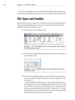
FIGURE 10.23: Starting a diagonal reference line with tracking points
(top) and the completed diagonal line (bottom)
8. Turn off Quadrant as a running osnap.
9. Start the Copy command, and select the entire front elevation and
nothing else. Then, press ↵.
Generating the Other Elevations 417
26531ch10.qxd 3/30/07 6:10 PM Page 417
10. For the base point, select the left endpoint of the ground line.
11. For the second point, pick the Intersection osnap, and place the cur-
sor on the diagonal line. When the x symbol with three dots appears,
click. Then, move the cursor to any point on the ground line of the
front elevation. An x appears on the diagonal line where the ground
line would intersect it if it were longer (see the top of Figure 10.24).
12. When the x appears, click to locate the copy. Press Esc to end the
Copy command. Zoom out to include the copy; then, use Zoom Win-
dow to include the floor plan and front elevations (see the bottom of
Figure 10.24). Press Esc to terminate the Copy command.
FIGURE 10.24: Making a copy of the front elevation (top) and adjusting
the view (bottom)
Chapter 10 • Generating Elevations418
26531ch10.qxd 3/30/07 6:10 PM Page 418
13. Start the Rotate command, and select this copy of the front elevation;
then, press ↵. Pick the Intersection osnap, and click the intersection
of the diagonal line with the ground line. For the angle of rotation,
enter 90↵ (see the top of Figure 10.25).
FIGURE 10.25: Rotating the copy of the front elevation (top) and the moved copy with
the view adjusted (bottom)
Generating the Other Elevations 419
26531ch10.qxd 3/30/07 6:10 PM Page 419
14. Start the Move command, and when prompted to select objects, enter
p↵↵. The rotated front elevation is selected. For the base point, click a
point in a blank space to the right of the upper endpoint of the ground
line of the rotated elevation. For the second point, move the cursor
down using polar tracking until the top of the ground line is lower
than the bottom line of the front step in the plan view. Then, click.
15. Zoom out and use Zoom Window to adjust the view (see the bottom
of Figure 10.25).
If you’re working on a smaller monitor than I am, you might have to do some
extra zooming in and out that isn’t mentioned in these steps.
The rest of the process for creating the right elevation is straightforward and
uses routines you have just learned. Here’s a summary of the steps:
1. Set up a new UCS for the right elevation. (Enter ucs↵ z↵ 90↵.) Use
the Plan command to rotate the drawing to the current UCS.
2. Drop lines from the floor plan across the height lines, which you’ll
produce from the copied elevation.
3. Trim these lines as required, and add any necessary lines.
4. Erase the copy of the front elevation and the diagonal transfer line.
5. Use grips to adjust the length and placement of the ground line.
(Click one of the grips on the endpoint, move the cursor left or right,
and click again.)
6. Name and save the UCS and view.
TIP
When creating elevations, you might accidentally draw a line over
an existing line. To catch this error, start the Erase command, and use a cross-
ing window to select the suspect line. In the command window, the number of
objects selected appears. If more than one line has been selected, cancel,
restart the Erase command, and pick the line again. This time, only the extra
line is selected, and you can erase it. If more than two lines are on top of each
other, repeat the process.
You can create the left elevation from a mirrored image of the right elevation.
Here are the steps:
1. Mirror the right elevation to the opposite side.
2. Set up a UCS for the left elevation (ucs↵ z↵ -90↵). Use the Plan com-
mand to rotate the drawing to the current UCS.
Chapter 10 • Generating Elevations420
Ǡ
You won’t be able to
get the height line
for the sliding-glass
doorframe from the
front elevation. It’s 2"
below the top win-
dow line.
26531ch10.qxd 3/30/07 6:10 PM Page 420
3. Revise the elevation to match the left side of the cabin.
4. Name and save the UCS and view.
When you have completed all the elevations, follow these steps:
1. Return to the WCS.
2. Display the Plan view.
3. Erase any remaining construction lines and the rotated front elevation.
4. Copy and rotate the FLOOR PLAN label under each of the plans, and
edit their content appropriately.
5. Zoom out slightly for a full view of all elevations. The drawing looks
like Figure 10.26.
FIGURE 10.26: The finished elevations
6. Create three more layers named B-elev, L-elev, and R-elev, all using
color 42.
7. Change the layer for each elevation’s line work and label to the asso-
ciated layer that you just made.
8. Save the drawing as
Cabin10b.dwg.
Once an elevation is drawn, you can rotate it to the same orientation as the
front elevation and move it to another area of the drawing.
Generating the Other Elevations 421
26531ch10.qxd 3/30/07 6:10 PM Page 421
Considering Drawing Scale Issues
This last view raises several questions: How will these drawings best fit on a
page? How many pages will it take to illustrate these drawings? What size sheet
should you use? At what scale will the drawing be printed? In traditional hand
drafting, you wouldn’t be able to draw the first line without answers to some of
these questions. You have completed a great deal of the drawing on the com-
puter without having to make decisions about scale and sheet size because, in
AutoCAD, you draw in real-world scale or full-scale. This means that when you
tell AutoCAD to draw a 10' line, it draws it 10' long. If you inquire how long the
line is, AutoCAD will tell you that it’s 10' long. Your current view of the line
might be to a certain scale, but that changes every time you zoom in or out. The
line is stored in the computer as 10' long.
You need to make decisions about scale when you’re choosing the sheet size,
putting text and dimensions on the drawing, or using hatch patterns and noncon-
tinuous linetypes. (Chapter 11 covers hatch patterns.) Because you have a dashed
linetype in the drawing, you had to make a choice about scale in Chapter 6, when
you assigned a linetype scale factor of 24 to the drawing. You chose that number
because when the drawing consisted of only the floor plan and the view was
zoomed as large as possible while still having all objects visible, the scale of the
drawing was about
1
⁄2" = 1'-0". That scale has a true ratio of 1:24, or a scale factor
of 24. You’ll get further into scale factors and true ratios of scales in the next
chapter.
If you look at your
Cabin10b drawing with all elevations visible on the screen,
the dashes in the dashed lines look like they might be too small, so you might
need to increase the linetype scale factor. If you were to thaw the title block’s
layer now, you would see that your drawings won’t all fit. Don’t worry about that
now. Beginning with the next chapter, and right on through the end of this
book, you’ll need to make decisions about scale each step of the way.
Drawing Interior Elevations
You construct interior elevations using the techniques you learned for con-
structing exterior elevations. You drop lines from a floor plan through offset
height lines and then trim them away. Interior elevations usually include fix-
tures, built-in cabinets, and built-in shelves, and they show finishes. Each eleva-
tion consists of one wall and can include a side view of items on an adjacent wall
if the item extends into the corner. Not all walls appear in an elevation—usually
Chapter 10 • Generating Elevations422
26531ch10.qxd 3/30/07 6:10 PM Page 422
only those that require special treatment or illustrate special building compo-
nents. You might use one elevation to show a wall that has a window and to
describe how the window is treated or finished and then assume that all other
windows in the building will be treated in the same way unless noted otherwise.
Figure 10.27 shows a few examples of interior wall elevations. Try to identify
which walls of the cabin each one represents.
FIGURE 10.27: Samples of interior elevations of the cabin
In the next chapter, you’ll learn how to use hatch patterns and fills to enhance
floor plans and elevations.
If You Would Like More Practice…
Here are three exercises for practicing the techniques you learned in this chap-
ter. The last one will give you practice in basic orthogonal projection.
Exterior elevations Open
Cabin10b.dwg, and move the right, left, and rear
elevations around so they fit in a line.
Interior elevations For some practice with interior elevations, try drawing
one or two elevations, using Figure 10.27 (shown earlier) as a guide. You can
measure the heights and sizes of various fixtures in your own home or office as
a guide. Save what you draw as
Cabin10c.dwg.
Orthogonal projection Draw the three views of the block shown in Fig-
ure 10.28 following the procedures you used for the cabin elevations, except
that, in this case, use the procedure that mechanical drafters employ; that is,
draw the front view first, and then develop the top and right side views from
the front view.
If You Would Like More Practice… 423
26531ch10.qxd 3/30/07 6:10 PM Page 423
FIGURE 10.28: Front, top, and side views of a block
Are You Experienced?
Now you can…
0 draw an exterior elevation from a floor plan
0 use grips to copy objects
0 add detail to an elevation
0 set up, name, and save a UCS and a new view
0 transfer height lines from one elevation to another
0 copy, move, and rotate elevations
2.0
3.0
1.0
3.0
3.04.0
1.0 DIA
TOP
1.0
1.0 1.0
2.0
2.0
1.0
1.5
FRONT
RIGHT SIDE
6.0
Chapter 10 • Generating Elevations424
26531ch10.qxd 3/30/07 6:10 PM Page 424
CHAPTER 11
Working with Hatches
and Gradients
Ǡ
Selecting a predefined hatch pattern and applying it to a drawing
Ǡ
Setting up and applying user-defined hatch patterns
Ǡ
Modifying the scale and shape of a hatch pattern
Ǡ
Specifying the origin of a hatch pattern
Ǡ
Filling an enclosed area with a solid color
Ǡ
Filling up an enclosed area with a gradient
Ǡ
Setting up and using palettes and palette tools
26531ch11.qxd 3/30/07 6:14 PM Page 425
H
atches can be abstract patterns of lines, they can be solid fills, or they can
resemble the surfaces of various building materials. Gradients are visual
features that shift from one solid color to another over a specified distance.
To give the appearance of texture to a drawing, an AutoCAD user will hatch
in areas or fill them in with a solid color or gradient. Solid fills in a drawing can
give a shaded effect when printed using screening, plotting an object using less
than 100 percent ink density, which results in a look quite different from the solid
appearance in the AutoCAD drawing on the screen. Chapter 15 covers screening.
In an architectural floor plan, the inside of full-height walls are often hatched
or filled to distinguish them from low walls. Wood or tile floors can be hatched to
a parquet or tile pattern. In a site plan, hatches distinguish between areas with
different ground covers, such as grass, gravel, or concrete. When you’re working
with elevations, you can hatch almost any surface to show shading and shadows,
and realistic hatch patterns can illustrate the surfaces of concrete, stucco, or
shingles. Hatches and fills are widely used in mechanical, landscaping, civil,
structural, and architectural details as a tool to aid in clear communication. Be
sure that your hatch patterns add to the readability of your drawings and do not
hinder it by making the drawings appear cluttered.
To learn how to hatch and fill areas, you’ll start with some of the visible sur-
faces in the front elevation of the cabin. You’ll then move to the floor plan and
then hatch the floors and put hatch patterns and fills in the walls and a gradient
on the balcony. You’ll use the Hatch and Gradient dialog box for all hatches and
gradients. It’s a tool with many options that you can use to create a sense of
depth or texture to your drawings.
A key part of a hatch pattern is the boundary of the pattern. You define the
area being hatched through a procedure called ray casting in which AutoCAD
searches the drawing for lines or objects to serve as the hatch boundary.
Hatching the Front Elevation
Hatches and fills should be on their own layers so they can be turned off or
frozen without also making other objects invisible. You’ll begin the exercise by
creating new layers for the hatches and assigning colors to them:
1. Open the
Cabin10b.dwg drawing. It should contain the floor plan,
elevations, and the door schedule. Freeze the layers for the right, left,
and back elevations and, if necessary, the table, title block, and grid.
TIP
To see the best visual effect from putting hatch patterns on the front
elevation, change the background color for the drawing area to white. Choose
Tools
➣ Options to open the Options dialog box, and then click the Display
tab. Click the Colors button, and make the change.
Chapter 11 • Working with Hatches and Gradients426
26531ch11.qxd 3/30/07 6:14 PM Page 426
2. Set up three new layers as follows:
Layer Name Color
Hatch-elev-brown 42
Hatch-elev-gray Gray (8)
Hatch-elev-black Black (White) (7)
3. Make the Hatch-elev-gray layer current. Now any new objects you
create will be assigned to this layer.
4. Click the Hatch icon on the Draw toolbar to open the Hatch And Gradi-
ent dialog box (see Figure 11.1). Be sure the expansion arrow in the
lower-right corner is pointing to the left. If it isn’t, click it to expand the
dialog box to its full size. You’ll use this dialog box to choose a pattern,
set up the pattern’s properties, and determine the method for specifying
the boundary of the area to be hatched. The Hatch tab should be active.
If it’s not, click the tab. Predefined and ANSI31 should appear in the
Type and Pattern drop-down lists, respectively. If not, open the lists, and
select those options.
FIGURE 11.1: The Hatch And Gradient dialog box
Hatching the Front Elevation 427
ǡ
You can also start
the Hatch command
by choosing
Draw
➣ Hatch or
by typing h↵.
26531ch11.qxd 3/30/07 6:14 PM Page 427
5. Move to the right of the Pattern drop-down list, and click the Browse
button to open the Hatch Pattern Palette dialog box (see Figure 11.2).
This palette is where you select the actual hatch pattern that you’ll use.
Of the four tabs, ANSI is active, and the ANSI31 pattern is highlighted.
FIGURE 11.2: The Hatch Pattern Palette dialog box
6. Click the Other Predefined tab. Find the AR-RROOF pattern, click it,
and then click OK. Back in the Hatch And Gradient dialog box, note
that AR-RROOF has replaced ANSI31 in the Pattern drop-down list. A
new pattern appears in the Swatch preview box, which is below the
Pattern list (see Figure 11.3).
You can change the Scale and Angle settings in their drop-down lists,
which are below the Swatch preview box. In the Angle drop-down list,
the preset angle of 0.00 is fine, but you need to adjust the Scale setting.
7. The Scale drop-down list contains preset scale factors that range
from 0.2500 to 2.0000. To set the scale to 6, you have to enter it man-
ually. In the Scale drop-down list, delete 1.0000, and enter 6, but do
not press ↵; just proceed to step 8, and continue the procedure. (That
is, create the hatch, and then press ↵. The next time you open the
dialog box in the current drawing, you’ll see that 6 has been added to
the drop-down list and is displayed as 6.0000.)
8. In the Options section in the middle of the dialog box, check the
Associative option. Associative hatches automatically update the areas
they cover whenever their boundaries change. If you delete any com-
ponent of the boundary, however, the hatch becomes nonassociative.
Chapter 11 • Working with Hatches and Gradients428
26531ch11.qxd 3/30/07 6:14 PM Page 428
FIGURE 11.3: The Hatch And Gradient dialog box with the AR-RROOF pat-
tern chosen
9. Move to the upper middle of the dialog box, and click the Add: Pick
Points button. This returns you to the drawing.
10. In the elevation view, click the middle of the roof area. The lines that
form the boundary of the roof area become dashed, displaying an out-
line of the area to be hatched (see Figure 11.4).
FIGURE 11.4: The roof’s boundary is selected.
Hatching the Front Elevation 429
26531ch11.qxd 3/30/07 6:14 PM Page 429
11. Right-click, and choose Preview from the shortcut menu. In the preview
drawing, look at how the hatch will appear. This hatch looks fine for now.
12. Press ↵ or right-click to accept this hatch. The hatch is now placed in
the roof area (see Figure 11.5).
FIGURE 11.5: The finished hatch pattern in the roof area
13. Zoom in to a view of just the front elevation. Notice how the appear-
ance of the hatch pattern changes as the roof gets larger on the screen.
Looking at Hatch Patterns
Let’s take a short tour through the available patterns:
1. Start the Hatch command.
2. In the Hatch And Gradient dialog box, be sure that the Hatch tab is
active. Then, click the Browse button next to the Pattern drop-down
list to open the Hatch Pattern Palette dialog box.
3. Make the Other Predefined tab active if it isn’t already. Look at the
display of hatch patterns. Eleven pattern names begin with AR-,
including the one just used. These patterns have been designed to
look like architectural and building materials, which is why you see
Chapter 11 • Working with Hatches and Gradients430
26531ch11.qxd 3/30/07 6:14 PM Page 430
the AR prefix. In addition to the roof pattern you just used, you’ll see
several masonry wall patterns, a couple of floor patterns, and one pat-
tern each for concrete, wood shakes, and sand.
4. Scroll down the display, and observe the other non-AR patterns.
They’re geometrical patterns, some of which use common conven-
tions to represent various materials.
5. Click the ANSI tab, and look at a few of the ANSI patterns. These are
abstract line patterns developed by the American National Standards
Institute and are widely used by public and private design offices in
the United States.
6. Click the ISO tab. These are also abstract line patterns developed by
another organization, the International Organization for Standard-
ization. The Custom tab is empty unless custom hatch patterns have
been loaded into your copy of AutoCAD.
7. Click Cancel in the Hatch Pattern Palette dialog box. Click Cancel
again to close the Hatch And Gradient dialog box.
As you work with hatch patterns, you’ll need to adjust the scale factor for each
pattern so the patterns will look right when the drawing is printed. The AR pat-
terns are drawn to be used with the scale factor set approximately to the default of
one to one (displayed as 1.0000) and should need only minor adjustment. How-
ever, even though the treatment you just chose for the roof is an AR pattern, it is
something of an anomaly. Instead of using it as is, you had to change its scale fac-
tor to 6.0000 to make it look right in the drawing.
TIP
When you’re using one of the AR patterns, leave the scale factor at
1.0000 until you preview the hatch; then you can make changes. This rule
also applies to the 14 ISO patterns displayed on the ISO tab of the Hatch Pat-
tern Palette dialog box.
For the rest of the non-AR patterns, you’ll need to assign a scale factor that
imitates the true ratio of the scale at which you expect to print the drawing.
Table 11.1 gives the true ratios of some of the standard scales used in architec-
ture and construction.
Hatching the Front Elevation 431
26531ch11.qxd 3/30/07 6:14 PM Page 431
T ABLE 11.1: Standard Scales and Their Corresponding Ratios
Scale True Scale Factor
1" = 1'-0" 12
1
⁄2" = 1'-0" 24
1
⁄4" = 1'-0" 48
1
⁄8" = 1'-0" 96
1
⁄16" = 1'-0" 192
The scale is traditionally written by mixing inches with feet in the expression,
which causes some confusion. For example, the third scale in the table, com-
monly called quarter-inch scale, shows that a quarter inch equals one foot. A
true ratio of this scale must express the relationship using the same units, as in
1
⁄4" = 1'-0". Simplifying this expression to have no fractions, you can translate it
to, say, 1" = 48". This is how you arrive at the true scale factor of 48, or the true
ratio of 1:48.
As you continue through this chapter, take special note of the various scale
factors used for different hatch patterns.
Hatching the Rest of the Front Elevation
You’ll apply hatches to the foundation, front door, and front wall. You’ll then
work with some special effects.
Using a Concrete Hatch on the Foundation
For the foundation hatch, keep the Hatch-elev-gray layer current. Follow
these steps:
1. To represent the top of the foundation, draw lines from the upper-left
and upper-right corners of the step to the edges of the building (see
the top of Figure 11.6). Activate osnaps as needed.
2. Start the Hatch command. Then, click the Browse button next to the
Pattern drop-down list in the Hatch And Gradient dialog box.
3. Activate the Other Predefined tab. Find and select the AR-CONC pat-
tern, and click OK.
4. Open the Scale drop-down list, and select 1.0000.
Chapter 11 • Working with Hatches and Gradients432
26531ch11.qxd 3/30/07 6:14 PM Page 432
5. Click Add: Pick Points. Then, in the drawing, click once in each rec-
tangle representing the foundation. The borders of these areas dash.
6. Right-click, and choose Preview. Then, right-click again to accept the
hatch. The concrete hatch pattern is applied to the foundation sur-
faces (see the bottom of Figure 11.6).
FIGURE 11.6: The front elevation with foundation lines drawn (top) and
the resulting hatches in place (bottom)
Hatching the Front Door and Wall
For the front door, you’ll use a standard hatch pattern, ANSI31. This is the
default pattern when you first use the Hatch command, but now the default pat-
tern is the last one used. Here are the steps:
1. Start the Hatch command, and click the Browse button.
2. Activate the ANSI tab. Select ANSI31, and click OK.
3. In the Scale text box, highlight 1.0000, and enter 18. Then, click Add:
Pick Points.
4. Click the middle of the door. The edges of the door and door still
become dashed.
5. Right-click, and choose Preview. If you stopped with a simple rectan-
gular door, right-click again. The door is hatched (see Figure 11.7). If
not, then go on to step 6.
Hatching the Front Elevation 433
26531ch11.qxd 3/30/07 6:14 PM Page 433
FIGURE 11.7: Hatching the simple door
If you created a more complex door, notice how the inner, closed
areas are also dashed. AutoCAD refers to these nested, closed areas
as islands, and you must instruct the program how to hatch these
areas. For example, should the hatch pattern stop at the first island
it encounters and discontinue filling in the areas altogether? Should it
ignore any islands and fill the boundary completely? Should it stop
at the perimeter of the first island, skip the area between that island
and the perimeter of the next, and then restart the hatch pattern
inside the next nested boundary? The third option is the default solu-
tion; unless you direct otherwise, AutoCAD will alternate hatching in
every other closed island area.
6. Click the spacebar to return to the Hatch And Gradient dialog box. In
the Islands area, click the Outer radio button or graphic. This
instructs AutoCAD to stop the hatch at the first island and disregard
any nested islands.
Chapter 11 • Working with Hatches and Gradients434
26531ch11.qxd 3/30/07 6:14 PM Page 434
7. Click the Preview button at the lower-left corner of the dialog box,
and then right-click to accept the hatch. The hatch stops at the first
island, as shown in Figure 11.8.
FIGURE 11.8: Hatching the complex door
8. Change the current layer to Hatch-elev-brown.
9. Start the Hatch command, and go through the same process to apply
a hatch to the wall. This time, you’ll use the AR-RSHKE pattern,
which looks like wood shingles (often called shakes). Here is a sum-
mary of the steps:
a. Click the Browse button.
b. Activate the Other Predefined tab, select the AR-RSHKE pattern,
and click OK.
c. Set Scale to 1, and click Add: Pick Points.
d. Pick any place on the front wall that’s not inside a window or a
window frame.
e. Right-click, choose Preview, and then right-click again.
The wall is hatched (see Figure 11.9).
FIGURE 11.9: The hatching of the front wall is complete.
Hatching the Front Elevation 435
26531ch11.qxd 3/30/07 6:14 PM Page 435
TIP
Using the Preview option is not required each time you create a
hatch, but it’s a useful tool. It can prevent you from having to erase or undo
and then re-create a hatch.
Using a Solid Fill Hatch
The windows will be hatched with a solid fill. You apply this hatch in the same
way as the other hatches you’ve been using, except that you don’t have a choice
of scale or angle:
1. Make Hatch-elev-black the current layer.
2. Start the Hatch command, and then click the Swatch sample box.
This is another method of opening the Hatch Pattern Palette dialog
box. Make sure the Other Predefined tab is active, and select the first
pattern, SOLID. Click OK. Back in the Hatch And Gradient dialog
box, note that the text boxes for Scale and Angle aren’t available.
These don’t apply to solid fills.
3. Click Add: Pick Points. In the drawing, select a point in the middle of
each of the glass panes. You’ll have to click the round window four
times because of the mullions (the separators between the panes).
4. Right-click, choose Preview, and then right-click again. The windows
have a solid black (or white) fill (see Figure 11.10).
FIGURE 11.10: The windows with a solid fill hatch
TIP
Depending on the quality and resolution of your monitor, solid fills
can appear to flow over thin, nonhatched areas. This is only an illusion; the
hatch actually stops at the border, as you can see if you zoom into an area in
question.
Chapter 11 • Working with Hatches and Gradients436
26531ch11.qxd 3/30/07 6:14 PM Page 436
Adding Special Effects
To finish the front elevation, you need to show shading and work a little with a
curved surface.
Implying Shading with a Gradient
When shaded surfaces are illustrated on an exterior elevation, they give a
three-dimensional quality to the surface. You’ll put some additional hatching
at the top portion of the wall to illustrate the shading caused by the roof
overhang.
You need to hatch the top 2'-6" of the wall with a gradient. To determine the
boundary line of the hatch, you’ll turn off the layer that has the shake pattern.
You’ll then create a guideline to serve as the lower boundary of the hatch:
1. Make a new layer named Hatch-hidden, and make it current. Then,
turn off the Hatch-elev-brown layer.
2. Use the Rectangle command and the Endpoint osnap to start a rec-
tangle at the top of the left wall, just beneath the soffit.
3. At the
Specify other corner point or [Area/Dimensions/
Rotation]: prompt, enter @25',-2'6↵ to make a rectangle that
extends the width of the cabin and down 2'-6" from the soffit. In
Figure 11.11, the rectangle is in bold for clarity.
FIGURE 11.11: Creating the boundary for the forthcoming gradient
4. Make the Hatch-elev-black layer current, and then start the Hatch
command. In the Hatch And Gradient dialog box, click the Gradient
tab. This is similar in layout to the Hatch tab (see Figure 11.12).
Hatching the Front Elevation 437
26531ch11.qxd 3/30/07 6:14 PM Page 437
FIGURE 11.12: The Gradient tab of the Hatch And Gradient dialog box
5. In the Color area, make sure One Color is selected, and then click the
Browse button next to the color swatch to open the Select Color dia-
log box. Unlike hatches, gradients do not get their color from the layer
they are on; you must explicitly select the color. Select color 250 in
the bottom row of swatches (see Figure 11.13), and then click OK.
FIGURE 11.13: Selecting the gradient color
Chapter 11 • Working with Hatches and Gradients438
26531ch11.qxd 3/30/07 6:14 PM Page 438