Autodesk Revit Architecture 2011 No Experience Required - part 13 pot
Bạn đang xem bản rút gọn của tài liệu. Xem và tải ngay bản đầy đủ của tài liệu tại đây (425.76 KB, 10 trang )
Chapter 2 • Creating a Model
94
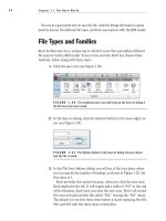
2. In the Properties dialog, click the Edit Type button, as shown in
Figure 2.80.
FIGURE 2.80 The Edit Type button in the Properties dialog
3. The contents of the Properties dialog that appears first contain the
instance parameters. Anything you change here applies to only the
one window you have selected. Click the Edit Type button.
TIP
If you know that you want to change an instance parameter (such
as sill height) for every window in the model, you can. Knowing that an
instance parameter only applies to one item, instead of picking just one
window, you can pick a window, right-click, and choose Select All Instances.
From there you can change every window’s parameters in the Properties
panel because you had every window selected.
4. Scroll down until you see Type Mark. Notice this value is set to A. This
is the property you changed by typing the value into the tag in the
model. Revit works both ways. If you change a symbol in the model, it
will change the parameter value within the family (see Figure 2.81).
Windows are among the most difficult items in Revit to use out of the box
without any real customization. In Chapter 17, we will dive into creating some
custom Revit windows. For now, however, remember the lessons learned in this
chapter. They will go a long way.
Are You Experienced?
95
FIGURE 2.81 Changing a type parameter changes every window of that type.
Are You Experienced?
Now you can…
place exterior walls
place interior walls
add reference planes
join walls
use the Split command
edit a cut profile
add doors
add openings
add windows
CHAPTER 3
Creating Views
One of Revit Architecture’s strongest points is the fact that it is one sin-
gle model. This single model, however, has to be broken down into a tangible
format that allows the user to navigate through a project. Chapters 1 and 2
featured the Project Browser (and it will be featured in this chapter as well),
but what is the Project Browser managing? Well, it’s simply managing views
of the model. Here’s an example: in the Project Browser, under Floor Plans
you usually see Level 1. This is a view of the model that just so happens to be
a floor plan. Under Elevations (Building Elevations), you see East Elevation,
North Elevation, South Elevation, and West Elevation. These are exactly the
same as the floor plans in the sense that they are simply views of the model.
Creating and managing levels
Adding sectional and elevation views
Controlling your views for aesthetic values
Chapter 3 • Creating Views
98
Creating Levels
This chapter focuses on the creation of views and their relationship to the model.
We will start with possibly the most important function in Revit: creating levels.
The power of Revit comes with the single-model concept. By being able to add
levels to a model, you are also adding floor plans. This two-way interaction is
what makes Revit the BIM choice for many users.
As you wander through the floor plans in the Project Browser, you will see Level 1
and Level 2. Not every job you will work on will have only a Level 1 and a Level 2.
Our task in this section is to create new levels that are appended to floor plans.
To follow along, open the model you have been working on, or go to www.sybex
.com/go/revit2011ner, and browse to the Chapter 3 folder. Open the file called
NER-05.rvt. If you wish, you can use an actual project you are working on. You
will just have to replace any names and specific dimensions with ones that are
applicable to your project. Perform these steps:
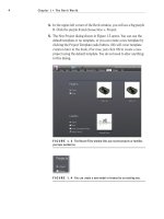
1. In the Project Browser, double-click on the South elevation. It is
located under Elevations (Building Elevations), as shown in Figure 3.1.
Notice at the right side of the building there are two symbols with
a datum at the end. These are elevation markers. Unfortunately, right
now they are somewhat obscured by the exterior wall. Zoom in to
this area, as shown in Figure 3.2.
FIGURE 3.1 Finding an elevation in the Project Browser
TIP
If, as you progress through the next few steps, you don’t see what
is shown in the next two figures, try zooming in more and repeating the
instructions.
Creating Levels
99
FIGURE 3.2 When dealing with levels, it is a good idea to zoom in close so
you can manipulate them.
2. Select (left-click) Level 1. Notice you will get several blue icons,
dimensions, and a lock.
Where the actual level line intersects the datum bubble, there is
a hollow blue circle (grip), as shown in Figure 3.3, except that your
view will be slightly obscured by the wall. Move the bubble so that
you can see the grip clearly.
3. Left-click (pick) and hold the pick button on the mouse. You can now
drag the bubble to the right.
FIGURE 3.3 Picking the grip to drag the level out of the way
Chapter 3 • Creating Views
100
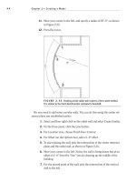
4. When you get to a point where the Level marker is outside the build-
ing, pick a spot to place the bubble and the annotation.
5. Press Esc.
Now that the levels are physically in a position where you can work on them,
you can start building on them.
Adding Levels
Adding an entirely new level in Revit Architecture is quite simple. But you need
to adhere to certain procedures in order to ensure you add the levels correctly.
When you use the Level feature in Revit, two procedural aspects stand out. The
first is to look at your Options bar after you start the command. The second is to
click the Modify button when you have finished. It is easy to get confused as to
how Revit wants you to proceed with adding a level, and it is also easy to inadver-
tently create multiple levels. Remember, in Revit you are always in a command.
To add a level, follow along:
1. On the Datum panel of the Home tab, click the Level button, as
shown in Figure 3.4.
FIGURE 3.4 Adding a level from the Datum panel on the Home tab
If you hover over
any item in Revit
Architecture and
pause for a second,
you will see what is
called a tooltip. This
will help you verify
you are selecting the
correct item.
Creating Levels
101
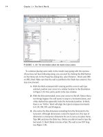
2. On the Draw panel on the Modify | Place Level tab, you will see that
you can either draw a line or pick a line, as shown in Figure 3.5. Make
sure Pick Lines is selected.
3. Also, on the Options bar, you will see the Make Plan View option.
Make sure it’s checked.
4. At the end of the Options bar, you will see a field for an offset. Type
10 and press Enter. Basically the approach here is to pick Level 2 and
create a new level that is offset 10
′–0″ above (see Figure 3.5).
FIGURE 3.5 Choosing the options for the Level command
5. With the options set, hover your cursor over Level 2.
Notice that when you come into contact with Level 2, a blue dot-
ted line appears. If you move your cursor slightly above the Level 2
line, the blue alignment line appears above Level 2. If you inch your
cursor slightly below Level 2, the blue alignment line appears below
Level 2.
6. When you see the blue line appear above Level 2, pick the Level 2
line, as shown in Figure 3.6.
FIGURE 3.6 Waiting for the alignment to appear
Chapter 3 • Creating Views
102
TIP
You may notice that speeding through the commands as you may
have done in AutoCAD is not helping you any in Revit. In Revit you may need
to slow down a bit, and let Revit “do its thing.” After you get the hang of
Revit’s behavior, you can speed up again.
7. You should now have a Level 3 at 20′–0″ (see Figure 3.7).
WARNING
Just because you have created a new level, this does
not tell Revit to shut down the command. Notice the Options bar is still
active and the Pick Lines icon still has the focus. If you start clicking around
in the view area, you will start creating levels. Every time you pick a point
on the screen, a new level will show up. Also, Revit does not care if you have
a level on top of another level. This situation can get ugly fast.
FIGURE 3.7 The completed Level 3. Remember, you are still in the Level
command until you tell Revit to stop.
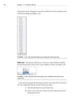
8. With the Level command still running, create Levels 4, 5, 6, and 7. Your
elevation should now look like Figure 3.8. Also, look at your Project
Browser. It should not have any additional levels. You may also notice
that you have new levels under the Ceiling plans category as well.
9. On the Select tab of the Ribbon, click the Modify button. You have
now safely terminated the Level command. (You can also press the
Esc key on your keyboard.)
Now that you have some experience adding levels, it is time to investigate the
physical level to see how it can be manipulated and modified.
Creating Levels
103
FIGURE 3.8 Levels 1 through 7 are now complete.
The Composition of a Level
Levels have controls that allow the user to adjust their appearance. As stated
throughout the book, when you select a family you will see that multiple items
turn blue. The blue color indicates that these items can be modified. When you
select a level, a few additional items will appear.
To investigate further, follow along:
1. Zoom in on Level 7.
2. Select Level 7 by picking (left-clicking) on either the text or the
actual level line itself. This will put the focus on the level line. Notice
the text that turns blue. We know that any blue item can be modified
(see Figure 3.9).
FIGURE 3.9 The selected level