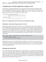
Google SketchUp Cookbook phần 7 pdf
Bạn đang xem bản rút gọn của tài liệu. Xem và tải ngay bản đầy đủ của tài liệu tại đây (1.1 MB, 39 trang )
Creating and Editing a Unique Texture
|
217
Creating and Editing a Unique Texture8.11
Problem
You want to make changes to the material of a specific face.
Solution
Make a unique texture for that face and then edit the material.
Discussion
This technique is useful when you have more than one face with a specific material and you
want to edit the material of only one of the faces. You make a unique texture for the face you
want to change and then edit just that material.
The advantage to making a unique texture is that you can add detail to a particular face without
changing all faces with the same material, and still keep the geometry simple. For example, you
could edit a stone material to have different-colored stones, which would be difficult to achieve
by adding extra geometry; you would need different materials for each new face.
In this example, you will use your graphics editor to add a sign and paint some of the bricks of
just one building in a row of identical buildings.
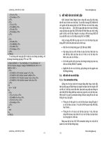
Download my 1. Coffee Shop model from the 3D
Warehouse (Figure 8-77). This is a row of shops.
You will edit the material of the middle shop.
Figure 8-77
Right-click on the middle brick façade and choose 2.
Make Unique Texture from the pop-up menu. This
adds a new material to the In Model folder of the
Materials window, which has the exact shape of the
face from which it was taken (Figure 8-78). The
name of the new material is derived from the name
of the original material, and you can change it if
you want.
To edit this material, right-click either on the 3.
thumbnail in the Materials window (in Windows
only) or on the material itself in the model. Choose
Edit Texture Image from the pop-up menu.
Figure 8-78
218
|
Chapter 8: Painting, Materials, and Textures
The new material appears in your default graph-4.
ics editor. Make some changes to the image. Figure
8-79 shows added text and some painted bricks.
Figure 8-79
Save the edited image and return to SketchUp. The 5.
middle façade now has the sign and painted bricks
(Figure 8-80). Those yellow bricks would have
taken more work to create within SketchUp and
would have increased the file size.
Note
The thumbnail for the new material in the Materials window
will reflect the changes you make in the graphics editor.
Figure 8-80
Using Alpha-Transparent Images8.12
Problem
You want to paint with a material that has a transparent background.
Solution
Use an alpha-transparent image, position it to fit what you’re painting, and hide edges if
necessary.
Using Alpha-Transparent Images
|
219
Note
You can use alpha-transparent images to create 2D Face Cam-
era components, which are simple 2D cutouts that always
face the same direction wherever you orbit, giving the look
and feel of a 3D object. For more information and for a discus-
sion of a problem with alpha images related to shadows, see
Recipe 9.4.
The Fencing folder of the Materials window has a few
materials with transparent backgrounds. To find more,
you can search the 3D Warehouse for alpha images or
its variations. The 3D Warehouse also has numerous
models of alpha-transparent trees and plants.
In the main example, you will create a railing around
a balcony by using an alpha-transparent image. In the
“Other Uses” section, you’ll see how a single alpha im-
age can be used to simplify an Eiffel Tower model, and
how to use an alpha image to make a ring of trees.
Download my Balcony House model from the 3D 1.
Warehouse (Figure 8-81).
The railing will be painted onto three vertical walls 2.
above the first floor. To make these walls, activate
Push/Pull, press the Ctrl/Option key, and then pull
up the first floor (Figure 8-82).
Erase the top face of this new box, which leaves just 3.
the three vertical walls (Figure 8-83).
Open the In Model folder of the Materials window 4.
and click the iron fence material. The background
color of this image is defined to be transparent.
Figure 8-81
Figure 8-82
Figure 8-83
Discussion
Images with alpha transparency have transparent backgrounds. Most graphics editors enable
you to define a certain color as transparent. The .png file format is best for supporting this type
of image. Alpha-transparent images are most commonly used for landscaping entourage (trees
and plants), for images of people, and for objects such as fences and railings.
Alpha-transparent images can be used to paint faces just like any other image, and the transpar-
ent parts of the image will be transparent in SketchUp. Edges around alpha-transparent faces
may appear to be hovering in space, but you can easily hide edges.
The greatest advantage of alpha-transparent images is that they enable you to reduce your file
size by using graphics instead of geometry. A 3D tree has a much higher number of edges and
faces than a 2D face painted with an alpha-transparent tree. A fence with repeated posts and
pickets is much more complex than a 2D face painted with an alpha-transparent fence image.
220
|
Chapter 8: Painting, Materials, and Textures
Paint one of the railing faces with the iron fence. 5.
You can see through the face, but the fence is the
wrong size (Figure 8-84).
Use texture positioning in Fixed Pins mode, drag-6.
ging the red pin to change the starting location, and
dragging the green pin to change the scale, so that
the image fits the face (Recipe 8.9). Right-click and
choose Done when finished.
Figure 8-84
Sample the edited material (press the Alt key in 7.
Windows or Cmd on the Mac while the Paint tool is
active, and click the positioned texture). Then paint
the other two faces (Figure 8-85). Just like when
you paint with translucent materials (Recipe 8.7),
alpha-transparent images are applied to both sides
of a face. (But you could override this by painting
one side with a different material.)
Figure 8-85
To make the railing look more realistic, hide its 8.
vertical edges and top horizontal edges (select these
edges, right-click on one of them, and choose Hide
from the pop-up menu). Figure 8-86 shows the
completed railing.
Figure 8-86
Using Alpha-Transparent Images
|
221
Other Uses
For a great example of how using an alpha-transparent
image can reduce your file size, download Google’s
Eiffel Tower model from the 3D Warehouse (Figure
8-87). It looks complex, but it’s actually a simple model
painted with an alpha image. This model can be found
in my 3D Warehouse collection for this chapter.
Figure 8-87
You can find the image in the In Model folder of the
Materials window (Figure 8-88). This image was ap-
plied to all four sides, using material positioning in Free
Pins mode to adjust the image to fit each face. Free Pins
mode is described in Recipe 9.1.
Figure 8-88
To see the unpainted model, switch from Shaded with
Textures mode to Shaded mode (Figure 8-89).
Figure 8-89
222
|
Chapter 8: Painting, Materials, and Textures
You can also use a single alpha image of a tree to make
a ring of trees. Figure 8-90 shows four vertical faces
painted with a tiling tree image.
When the edges of the faces are hidden, it looks like a
group of trees.
Figure 8-90
You can use Push/Pull on the faces to make a larger or
smaller ring of trees (Figure 8-91).
Figure 8-91
Continuing the discussion of painting and materials
from Chapter 8, this chapter focuses on using digital
photos to paint faces in your model, adding photo-
realism and saving modeling time.
Using photos to paint faces can reduce the num-
ber of geometric elements you need to create.
For example, you can take the time and effort to
model geometrically accurate windows on the
side of a building, or can you simply paint the
face with a photo of the side of that building. (If
you don’t have an actual photo, a rendering works
well, too.)
In addition to saving modeling time, using
photos this way can greatly reduce file size. For
this reason, Google encourages 3D Warehouse
contributors to use digital photos on their models
whenever possible. Many of the models in the
3D Warehouse are photorealistic, as are many 3D
buildings in Google Earth. Some of these models
represent extremely complex structures but are
modeled in simple geometry painted with photos.
To see some examples, open Google Earth with
the 3D Buildings layer turned on, and explore any
large city. Many buildings are plain gray, but a
large number are painted. (For more information,
see Chapter 13.)
CHAPTER 9
Modeling with Digital Photos
This chapter covers all you need to know about
painting with digital photos, including how to:
Fit a • photo to a face
Use photos to make 2D components that •
look 3D
Edit an imported photo•
Use photos to create 3D models•
Use Photo Match•
Note
For the basics of where to find materials and images
and how to get them into your model, see Recipes 8.1
and 8.2.
224
|
Chapter 9: Modeling with Digital Photos
Positioning Textures with Free Pins9.1
Problem
You want to fit a material to a face.
Solution
Use texture positioning in Free Pins mode.
Discussion
Free Pins mode is used to adjust a material so that it fits perfectly within a face. It is most com-
monly used to fit images, such as pictures of windows, doors, façades, or furniture. Free-pin
positioning is essentially distorting an image by pulling its corners, to constrain the image to a
face.
Note
The other positioning mode is Fixed Pins, which is used to
adjust the location, scale, and skew of a tiling material. Fixed
Pins mode is demonstrated in Recipe 8.9.
The main example demonstrates how to fit an image of
a door to a face. In the “Other Uses” section, you’ll see
how fixed pins can fit images to the façade of a building
or to faces of a bureau.
Download my 1. Custom Door model from the 3D
Warehouse (Figure 9-1). A picture of a custom
garage door will be painted on the white face.
Open the In Model folder of the Materials window, 2.
which contains the photo of the door. Paint the
door photo onto the face (Figure 9-2).
The scale and location are not correct, and the
lower edge of the door in the photo is not horizon-
tal. You will need to adjust the photo to fit within
the door face.
Figure 9-1
Figure 9-2
Positioning Textures with Free Pins
|
225
Right-click on the door and choose 3.
Texture→Position. If you see four multicolored pins
(fixed pins), right-click again and choose Fixed Pins
to deselect it. Free pins are all yellow and appear in
each corner of one of the tiled images (Figure 9-3).
Figure 9-3
Free pins are free because they can be picked up 4.
and placed anywhere and then dragged into an ex-
act position. To “lift” a pin, just click it. Then click
again to “drop” it where you want it on the image.
To place a pin accurately, you usually need to zoom
in very closely to find the correct points on the
photo. Using the Zoom window tool and the Previ-
ous View tool can speed this process up immensely.
In Figure 9-4, one pin was placed at each corner
of the rectangular part of the door, because these
points are easy to find. (It would be harder to place
a pin at the top of the arch.)
Note
When you lift and drop pins, look for dotted blue helper lines
that indicate when a pin is horizontal or vertical from another
pin.
Drag each pin to a corner of the door face in the 5.
model (Figure 9-5).
Note
Some users prefer to place all of the pins first and then drag
all of them into place. Others prefer to place a pin and drag
it, and then repeat for subsequent pins. Both methods work
fine; it’s a matter of preference.
If you need to tweak the image for a better fit, move 6.
and drag pins as needed. When the photo looks
correct, right-click on the door and choose Done.
The rectangular part of the door looks good, but
the top of the photo is cut off (Figure 9-6).
Figure 9-4
Figure 9-5
Figure 9-6
226
|
Chapter 9: Modeling with Digital Photos
Use the Move tool to move the top edge of the door 7.
up, passing the top of the door in the photo (Figure
9-7).
Figure 9-7
Use the 8. Arc tool to trace the top of the door in the
photo. Then use the Eraser to trim the rest of the
door face. This results in a single door face with the
correct photo (Figure 9-8).
Figure 9-8
For a more realistic garage door, use Push/Pull to 9.
push in the door slightly. The sides of the opening
will have the same material as the door, so repaint
them with the blue bricks (Figure 9-9).
Figure 9-9
Editing a Photo
|
227
Other Uses
Free-pin positioning can be used for a multitude of
models. For example, Figure 9-10 began as a simple box
model, and then each face was painted with a photo of
a building façade. Compare the file size of this painted
box (about 2.5MB because the graphic files themselves
are large) with the 5MB size of an actual geometric
model including all of those windows, doors, and orna-
mentation. Using graphics of smaller file size can keep
your file size quite low.
Figure 9-11 is a beautiful model of a Japanese bureau.
Each face is painted with a photo taken of a real piece of
furniture.
Figure 9-10
Figure 9-11
Editing a Photo9.2
Problem
You want to make changes to a photo used in your model.
Solution
Use the Edit Texture Image option and make the changes in your graphics editor. The image
will be updated in SketchUp automatically.
Discussion
If a material image in your model needs to be changed, you certainly could alter the original
graphic file. But what if your changes are minor? Or what if the changes apply only to the cur-
rent model? What if you want the image unaltered for other models? SketchUp provides a quick
fix: the Edit Texture Image option exports the image to your default graphics editor, in which
you can make your edits. Save the edited image, and the change appears in SketchUp automati-
cally. The original image is untouched; the changes apply only to the image within the current
SketchUp file.
In the main example, you’ll see how to fix an image on a billboard. In the “Other Uses” section,
you’ll see how to make a change to a tiling stone image.
228
|
Chapter 9: Modeling with Digital Photos
Note
Another method of touching up an image is described in
Recipe 9.3. With this method, you don’t edit the image itself;
you add new faces to “patch” the image.
Download my 1. Graffiti model from the 3D Ware-
house (Figure 9-12). The antigraffiti billboard has
been defaced with, well, graffiti. Also, the bottom of
the photo has some green leaves sticking out.
Right-click on the billboard face and choose 2.
Texture→Edit Texture Image. (In Windows, this
option is also available when you click on the image
thumbnail in the In Model folder of the Materials
window. On the Mac, when you edit a material,
there is an icon for Edit Texture Image at the bot-
tom of the Edit Material window.)
The original photo used to make the billboard
opens in your default graphics editor. (You can set
the default editor in the Applications page of the
Preferences window.)
Make the necessary changes to the photo. Figure 3.
9-13 shows the word Fun removed, and the green-
ery at the bottom trimmed above the billboard’s
frame.
Figure 9-12
Figure 9-13
Save and close the photo you edited and return to 4.
SketchUp. The billboard now shows the improved
photo (Figure 9-14).
The image in the In Model folder is updated as well,
but choosing Undo will bring back the original,
unchanged image. The changes have not affected
the source graphic file, only the graphic internal to
the current SketchUp model.
Figure 9-14
Adding Faces to Patch an Image
|
229
Other Uses
You can also edit a tiled image. Figure 9-15 shows two
buildings with stone material. Edit Texture Image is
used to add a blue and red stone. After you’ve saved the
image and returned to SketchUp, the tiled image has
been updated on all stone faces (Figure 9-16).
Figure 9-15
Figure 9-16
Adding Faces to Patch an Image 9.3
Problem
You want to patch over parts of an image in your model.
Solution
Draw a face over the area you want to patch, and position the texture within the new face.
Discussion
With the patching method, you do not edit the image you want to change; instead you add faces
over the parts you want to patch, and position the materials within those faces. In the main
example, you will see how to add faces to patch over some old windows, so that new windows
can be inserted. The “Other Uses” section demonstrates how this technique can be applied to
remove a logo from a truck.
Download my 1. New Windows model from the 3D
Warehouse (Figure 9-17). This is a renovation sce-
nario, in which the windows on the wall indicated
by the arrow will be removed and replaced with
new windows.
Figure 9-17
230
|
Chapter 9: Modeling with Digital Photos
Draw a rectangle around the first window, as shown 2.
in Figure 9-18.
Figure 9-18
Position the material in this rectangle, using either 3.
Fixed or Free Pins. In either mode, click and drag
the material itself (don’t drag a pin) slightly to the
left or right, so that the face contains only plain
bricks, keeping mortar lines aligned (Figure 9-19).
Figure 9-19
Right-click on the positioned material and choose 4.
Done. Now the material looks seamless, and the
window is removed, but you can still see the edges
of the new face (Figure 9-20).
Figure 9-20
If you erase these edges, the window in the photo 5.
will return. So hide the edges instead. You can se-
lect the four edges, right-click on one of them, and
choose Hide from the pop-up menu, or you can use
the Eraser with the Ctrl/Option key pressed and
click all four edges. Now you can’t tell there used to
be a window there (Figure 9-21).
Figure 9-21
Adding Faces to Patch an Image
|
231
Repeat this patching technique for the remaining 6.
windows on the wall (Figure 9-22).
Insert new windows on this wall. The windows 7.
shown in Figure 9-23 are available in the In Model
folder of this model’s Components window. This
demonstrates one of the problems you can encoun-
ter when using faces to patch an image: the wall is
no longer a single face, and the windows do not cut
the wall properly.
To fix the broken wall, first display the dashed lines 8.
indicating hidden edges (View→Hidden Geometry).
The dashed lines indicate the patching faces you
added.
Select the wall and all new windows, right-click on 9.
any selected face, and choose Intersect→Intersect
Selected from the pop-up menu. This creates
intersection edges on all faces where they meet the
windows. Then you can erase the edges that fall
within the new windows (Figure 9-24).
The patching method is a great quick fix for minor
touch-ups, especially if you prefer not to edit your
graphics. But if the patched face might be changed
afterward, such as getting new windows, editing the im-
age in advance (Recipe 9.2) might prove less work than
repairing a patched face.
Figure 9-22
Figure 9-23
Figure 9-24
Other Uses
You can also use the patching method to remove a logo
from a truck. In Figure 9-25, the blank space above the
logo is narrow. So create a face around the entire logo
and divide it in half, so that each half can be positioned
with a new strip of “blank” truck.
Figure 9-25
Position the material in each narrow rectangle to cover
the logo. Then hide the edges around each new rect-
angle (Figure 9-26).
Figure 9-26
232
|
Chapter 9: Modeling with Digital Photos
Using Images to Make Face Camera Components9.4
Problem
You want to use a 2D image to represent a 3D object.
Solution
Paint the image on a face. Trace a border around the image, trim away the rest of the face, and
hide the remaining edges. Then make this face into a Face Camera component.
Discussion
Certain types of objects in your model can be represented by 2D images that give the “feel” of
a 3D object, because they always face you no mater how you orbit the model. Good candidates
are such objects as people, trees, plants, street lamps, trash bins—objects that look basically the
same as you orbit around them (Figure 9-27).
In this example, you will create a Face Camera compo-
nent of a tree. The tree image is an alpha-transparent
image, which means its background is transparent
(Recipe 8.12).
Note
Face Camera components are also sometimes called Face
Me components. If you are searching the 3D Warehouse for
models like these, try both terms in your search.
Figure 9-27
Download my 1. Face Camera Tree model from the
3D Warehouse (Figure 9-28). The alpha-transparent
tree is painted on a vertical face next to the house.
Note that the shadow of the tree is a rectangle;
SketchUp’s shadows do not recognize transparent
images.
Figure 9-28
Orbit to a view like the one in Figure 9-29. The tree 2.
looks like a cardboard cutout at this angle. Plus you
can see the face’s edges.
Figure 9-29
Using Images to Make Face Camera Components
|
233
To get more accurate 3. shadows, you need to trim the
face to approximate the shape of the tree. Use the
Line or Arc tool to trace around the tree (Figure
9-30). Accuracy is not important for shadows, be-
cause nobody notices the level of detail in a shadow,
only its general shape. When tracing, be sure to
look for the On Face inference. Otherwise, you may
be drawing lines out of the plane of the face.
Note
Because this image has a transparent background, you don’t
have to trace around it exactly; the transparent background
means that extra space around the leaves won’t be noticed. If
you were trimming around an image with a visible back-
ground, you would want to trace the border more accurately,
so that no background would show. If black edges are hard to
see against the image, you can change the edge color in the
Styles window (Edit tab, Edge page).
Use the Eraser tool to trim the corners of the rect-4.
angular face, so that only the tree shape remains
(Figure 9-31). The shadow now looks tree-shaped.
The next step is to hide the edges around the tree. 5.
Activate Select and double-click the tree, which
selects both the face and its edges. Then press and
hold the Shift key to deselect the face, leaving only
the edges selected. Right-click on an edge and
choose Hide from the pop-up menu. The tree looks
quite natural (Figure 9-32).
Now the tree can be made into a component. Acti-6.
vate the Select tool and double-click the tree, which
selects both the face and its hidden edges. Right-
click on the tree and choose Make Component.
In the Create Component window, select 7. Always
Face Camera, make sure Replace Selection with
Component is selected, but leave Shadows Face Sun
off to ensure that the shadows appear properly.
Now you can insert more trees, which cast proper 8.
shadows and always face you when you orbit
around. Using various scales for the trees produces
a nice, random look (Figure 9-33).
Note
For details on how to use the Scale tool to make random-
looking components, see Recipe 7.9.
Figure 9-30
Figure 9-31
Figure 9-32
Figure 9-33
234
|
Chapter 9: Modeling with Digital Photos
Using Free Pins and a Single Image to Paint a 3D Object9.5
Problem
You want to use a 2D image to paint an unpainted 3D object.
Solution
Paint the image onto one face, and use free-pin positioning to fit the image to the face. Then
paint the remaining face based on the material of the first face.
Discussion
Recipe 9.1 demonstrates how to fit an image to a face. Based on that technique, you can create a
photorealistic model by painting each face of the model with the appropriate photo. This means
that, ideally, you should have one photo for each face (or at least one photo for each elevation
and plan view), and your unpainted model should have accurate dimensions. But what if you
have only one photo to work with?
If that one photo shows at least two faces of an object, you can use it to paint all faces that ap-
pear in the photo. With this technique, you first paint and position the image to one face of the
unpainted model. If necessary, add or remove geometry to accommodate the picture. Then you
can use that positioned material as a basis for painting the remaining faces that are shown in
the photo.
Two examples are used to demonstrate this technique. In Example 1, you will paint a barn, and
in Example 2, a truck.
Example 1: Barn with Free-Pin Positioning
In this example, you start with an unpainted box. After
painting and positioning the front face, you will com-
plete the model geometry. Then you will paint the rest
of the faces based on the material of the front face.
Download my 1. Barn model from the 3D Warehouse.
It is an unpainted box in the approximate shape of
a barn.
Open the In Model folder of the Materials window. 2.
This folder contains the image with which the barn
will be painted. The photo shows three faces: the
front, side, and roof of the barn. Paint the image
onto the front face of the barn (Figure 9-34).
Note
This technique requires an unpainted model
to start. If you want to create your model
from scratch based on a photo, use Photo
Match as described in Recipe 9.6. You can also
use Photo Match on an unpainted model as
explained in Recipe 9.7.
Figure 9-34
Using Free Pins and a Single Image to Paint a 3D Object
|
235
Position this material by using free pins, placing 3.
one pin at each corner of the rectangular part of the
barn’s front and dragging the pin to the corner of
the model face (Figure 9-35).
Tweak the image if needed. Then right-click on the 4.
image and choose Done. The front face of the box is
now painted with part of the front face of the barn
(Figure 9-36).
To accommodate the rest of the front face, pull up 5.
the top of the box until it reaches the top of the roof
in the photo. Trace the outline of the roof on the
front face (there are four edges). Then push back
the corners of the front face, to complete the roof
faces (Figure 9-37).
When tracing the roof, ideally the top of the roof
in the photo would meet the midpoint of the top
edge, and the roof itself would be perfectly sym-
metric. But it’s hard to achieve that sort of accuracy
with photos. You can base your tracing entirely on
the photo and get slightly inaccurate geometry, or
you can create accurate geometry and use free pins
to tweak the photo so that it fits better. It’s nearly
impossible to get perfect results, but you can get
pretty close. (If accuracy is important, it’s ideal to
start with a dimensionally accurate model on which
to paint. Fitting the model to a photo works, too,
but usually requires more steps and tweaking.)
Figure 9-35
Figure 9-36
Figure 9-37
Sample the material on the front face (press Alt in 6.
Windows or Cmd on the Mac while using the Paint
tool, and click the front face). Then click the side
face (Figure 9-38). This material is already correctly
positioned along the edge shared with the front
face, but the other two corners of the image need to
be positioned.
Figure 9-38
236
|
Chapter 9: Modeling with Digital Photos
Use free-pin positioning on this face and drag into 7.
place the two pins shown in Figure 9-39.
Figure 9-39
Paint the two roof faces the same way: sample the 8.
material either on the side or front and click the
roof face (Figure 9-40). If you paint the lower roof
face first, you will have to adjust only one pin per
face.
Figure 9-40
To paint the other side of the barn, sample the 9.
painted side and then click the unpainted side. The
resulting material is a mirror image of the original.
Paint the roof faces on this side by sampling the
side face below them. The finished barn is shown in
Figure 9-41.
Figure 9-41
Example 2: Truck with Free-Pin Positioning
In this example, you start with an unpainted model of
a truck and use a photo to paint the side and front. You
will modify geometry at the front and bottom of the
model to accommodate the whole photo.
Download my 1. Truck model from the 3D Ware-
house. It is an unpainted box in the approximate
shape of a truck.
Paint the side of the truck with the image in the 2.
In Model folder of the Materials window (Figure
9-42).
Figure 9-42
Using Free Pins and a Single Image to Paint a 3D Object
|
237
Use free pins to fit the rectangular part of truck to 3.
the side face.
Pull out the front of the box so that you can see the 4.
entire side of the truck in the photo, and pull down
the bottom so that you can see the tires (Figure
9-43).
The next step is to trace edges around the tires 5.
and along the side, but if your default edge color
is black, the tracing edges will be difficult to see
against the image. To change the edge color, open
the Styles window to the Edit tab and Edge page,
and set a contrasting color for edges.
Use lines and arcs to trace around the side of the 6.
truck, including the tires. (You could also use the
Circle tool for the tires.) The half-circles for the
tires should be separate faces. Push back the extra
faces (Figure 9-44).
Figure 9-43
Figure 9-44
To model the tires, use Push/Pull with the Ctrl/Op-7.
tion key on the half-circle faces. (The Ctrl/Option
key creates a new face; without Ctrl/Option, you
will just push the tires into the truck.) This creates
the edges on the other side of the tire (Figure 9-45).
Figure 9-45
Repeat this Push/Pull operation for the other tires. 8.
Then trim the bottom of the truck to leave only the
tires. Figure 9-46 shows the tires and truck bottom
painted black.
Figure 9-46
238
|
Chapter 9: Modeling with Digital Photos
To paint the front of the truck, sample the material 9.
on the side and click the front face (Figure 9-47).
Figure 9-47
Adjust this face by using free pins, and paint the re-10.
maining faces by using the same technique. Figure
9-48 shows the completed truck with edges turned
off.
Figure 9-48
Using Photo Match to Model a 3D Object9.6
Problem
You want to use a 2D image to model a 3D object from scratch.
Solution
Import the photo as a matched photo. Use points on the photo to set the origin and axes for the
model. Then draw your model based on the photo.
Discussion
Starting with a blank file (no existing geometry) and a photo that shows at least two faces of
your model, you can use Photo Match to achieve the same results as you accomplished with
Recipe 9.5’s free-pin positioning technique. With Photo Match, you set the model’s origin and
axes based on data in the photo. After these are established, you can trace your model based on
the photo, and then project textures from the photo onto faces in the model.
Using Photo Match to Model a 3D Object
|
239
Photo Match is great for a quick, preliminary design, for
which you have a photo but no accurate measurements
or dimensions. It is not extremely accurate, however. If
you are creating a serious photorealistic model, the ideal
solution is to start with a geometrically accurate model
for which each face (or elevation and plan views) has its
own photo. In this recipe you’ll re-create the barn and
truck from the free-pin positioning examples, so you
can compare the results.
Example 1: Barn with Photo Match
In this example, you will open the barn model used in
Recipe 9.5’s “Example 1: Barn with Free-Pin Position-
ing,” and save its barn image to your hard drive. That
image will be used to model the barn in a new file.
Download my 1. Barn model from the 3D Warehouse.
It contains one image in the In Model folder of the
Materials window.
In Windows, right-click on this image and choose 2.
Export Texture Image from the pop-up menu. Save
the image to your hard drive. On the Mac, edit the
texture and click the Edit Texture Image icon. This
opens the image in an external editor, from which
you can save it to your hard drive.
Start a new SketchUp file and then choose 3.
File→Import from the main menu. Make sure you
are looking for graphic file types and browse to the
barn photo you saved. Import it as a new matched
photo (Figure 9-49).
Figure 9-50 shows the photo of the barn with two
red and green axis bars, a blue axis to set the verti-
cal direction, and a yellow origin point.
The origin should be placed at the corner nearest to 4.
the camera, on the ground. Click and drag the yel-
low origin point and place it on the ground where
the front and side faces meet (Figure 9-51).
The red and green axis bars are used to define the 5.
red and green axes of the model. Use lines and
points in the photo to place and orient these bars.
To maximize accuracy, it’s good practice to place
the bars as far apart as possible, and to use the lon-
gest possible distance along each bar. Figure 9-52
shows the red bars along the top and bottom of the
side, and the green bars at the top and bottom of
the front.
Figure 9-49
Figure 9-50
Figure 9-51
Figure 9-52
240
|
Chapter 9: Modeling with Digital Photos
Check to see that the blue axis is vertical. When the 6.
axes look right, right-click on the image and choose
Done.
There is now a scene tab at the top of your Sketch-
Up window (Figure 9-53). If you orbit out of the
current view, you will lose the barn picture. To get
the picture back, you can click this tab.
The axes of your model are now aligned to the 7.
photo. Use the Line tool to trace over the rectangu-
lar part of the front of the barn, keeping the edges
in the respective axis directions (Figure 9-54).
Figure 9-53
Figure 9-54
Push this face back to the back of the barn (Figure 8.
9-55).
To pull the box up to add the roof, you first need 9.
to orbit out of the current view, which means the
photo will disappear. Because you can no longer
see the photo, push the top up by a large distance,
higher than you know it needs to be.
Click the scene tab to return to the view that has the 10.
photo. The model covers the picture, so switch to
X-Ray mode so that you can see the photo through
the model.
Trace the roof lines on the front face (Figure 9-56).11.
Figure 9-55
Figure 9-56
Using Photo Match to Model a 3D Object
|
241
Push back the top of the box to complete the roof 12.
(Figure 9-57) and then switch back to Shaded with
Textures mode.
Note
Here’s another way you could complete the roof: starting
from the initial box, orbit away from the photo and start the
Push/Pull operation. Then return to the photo and complete
the Push/Pull. Then you would trace the roof edges and push
back faces as described in the preceding steps.
To paint all of the visible faces, click Project Texture 13.
from Photo, found in the Sketch Over window. (You
can also paint an individual face by right-clicking it
and choosing Project Photo.)
The photo is projected on these faces, with more
or less the correct positioning (Figure 9-58). If any
faces need adjustment, you can position their mate-
rial by using free pins.
Orbit out of the current view. The photo disappears, 14.
but the barn faces remain painted (Figure 9-59).
Example 2: Truck with Photo Match
In this example, you will open the truck model used in
Recipe 9.5’s “Example 2: Truck with Free-Pin Position-
ing,” and save its image to your hard drive. That image
will be used to model the truck in a new file.
Download my 1. Truck model from the 3D Ware-
house. It contains one image in the In Model folder
of the Materials window.
Save the image to your hard drive as you did in step 2.
2 of Example 1.
Import the truck image as a matched photo, and set 3.
the axes and origin (see steps 3 and 4 of Example
1 for tips). Figure 9-60 shows the origin set at the
lower corner of the side of the truck, which is actu-
ally in the middle of the side face. It was placed here
so that the blue axis could be checked relative to the
top of the truck.
Note
You could also move the origin so that the side of the truck
starts at the origin. As long as the red and green axes are set
correctly, the origin can be anywhere, and the model geom-
etry can be adjusted accordingly.
Figure 9-57
Figure 9-58
Figure 9-59
Figure 9-60