Introduction to AutoCAD 2008 2D and 3D Design phần 6 pptx
Bạn đang xem bản rút gọn của tài liệu. Xem và tải ngay bản đầy đủ của tài liệu tại đây (5.75 MB, 38 trang )
CHAPTER 11
Sheet sets
Aims of this chapter
1. To introduce sheet sets.
2. To describe working in the Sheet Layout and Publishing workspace.
3. To give an example of a sheet set based on the design of a two-storey
house.
Sheet sets
When anything is to be manufactured or constructed, whether it be a
building, an engineering design, an electronics device or any other form
of manufactured artefact, a variety of documents, many in the form of
technical drawings, will be needed to convey to those responsible for
constructing the design information necessary to be able to proceed
according to the wishes of the designer. Such sets of drawings may be
passed between the people or companies responsible for the construc-
tion, enabling all those involved to make adjustments or suggest
changes to the design. In some cases there may well be a considerable
number of drawings required in such sets of drawings. In AutoCAD
2008 all the drawings from which a design is to be manufactured can be
gathered together in a sheet set. This chapter shows how a much
reduced sheet set of drawings for the construction of a house at 62
Pheasant Drive can be formed. Some other drawings, particularly detail
drawings, would be required in this example, but to save page space, the
sheet set described here consists of only four drawings and a subset of
another four.
A sheet set for 62 Pheasant Drive
1. Construct a template 62 Pheasant Drive.dwt based upon the
acadiso.dwt template, but including a border and a title block. Save
the template in a Layout1 format. An example of the title block
from one of the drawings constructed in this template is shown in
Fig. 11.1.
2. Construct each of the drawings which will form the sheet set in this
drawing template. The whole set of drawings is shown in Fig. 11.2.
Save the drawings in a directory – in this example this has been given
the name 62 Pheasant Drive.
178
Ch11-H8512.qxd 4/4/07 6:48 PM Page 178
Sheet sets 179
3. Click New Sheet Set in the File drop-down menu (Fig. 11.3). The first
of a series of Create Sheet Set dialogs appears – the Begin dialog
(Fig. 11.4). Click the radio button next to Existing drawings, followed
by a click on the Next button and the next dialog Sheet Set Details
appears (Fig. 11.5).
4. Enter details as shown in the dialog in Fig. 11.5. Then click the Next
button to bring the Choose Layouts dialog to screen (Fig. 11.6).
5. Click its Browse button and from the Browse for Folder list which
comes to screen, pick the directory 62 Pheasant Drive. Click the OK
button and the drawings held in the directory appear in the Choose
Layouts dialog (Fig. 11.6). If satisfied the list is correct, click the
Next button. A Confirm dialog appears (Fig. 11.7). If satisfied click
the Finish button and the Sheet Set Manager palette appears show-
ing the drawings which will be in the 62 Pheasant Drive sheet set
(Fig. 11.8).
62 Pheasant Drive
Scale:
Title:
Date: Drawing No:
1.50
12:09:07
2
Building plan
Fig. 11.1 The title block
from Drawing number 2 of
the sheet set
Sheet Set
Sub set
Existing boundary
Boarded
fences
Shooters Way
Scale:
2,500
3,000
4,000
7,000
10,000
Title:
Scale:
Title:
Scale:
Title:
Pheasant Drive
62 Pheasant Drive
Scale:
1.50
Date: Drawing No:
4D
13.09.07
Title:
Side view from West
62 Pheasant Drive
Scale:
1:100
Date: Drawing No:
412.09.07
Title:
Elevations
Rear
Fron t
Upper floor
Lounge
Dining
room
Kitchen
Ground floor
Bedroom 1
Bedroom
3
Bedroom
2
Side
Side
Fig. 11.2 The eight drawings in the
62 Pheasant Drive sheet set
Fig. 11.3 Selecting New Sheet
Set from the File drop-down
menu
Ch11-H8512.qxd 4/4/07 6:48 PM Page 179
180 Introduction to AutoCAD 2008
Notes
1. The eight drawings in the sheet set are shown in Fig. 11.8. If any of
the drawings in the sheet set are subsequently amended or changed,
when the drawing is opened again from the 62 Pheasant Drive
Sheet Set Manager palette, the drawing will include any changes or
amendments.
Fig. 11.4 The first of the Create
Sheet Set dialogs – Begin
Fig. 11.5 The Sheet Set Details
dialog
Ch11-H8512.qxd 4/4/07 6:48 PM Page 180
Sheet sets 181
2. Drawings can only be placed into sheet sets if they have been saved in
a Layout screen. Note that all the drawings shown in the 62 Pheasant
Drive Sheet Set Manager have Layout1 after the drawing names
because each has been saved after being placed in a Layout1 screen.
3. Sheet sets in the form of DWF (Design Web Format) files can be sent
via email to others who are using the drawings or placed on an
intranet. The method of producing a DWF for the 62 Pheasant Drive
Sheet Set follows.
Fig. 11.6 The Choose Layouts
dialog
Fig. 11.7 The Confirm dialog
Fig. 11.8 The Sheet Set
Manager palette for 62
Pheasant Driv
Ch11-H8512.qxd 4/4/07 6:48 PM Page 181
62 Pheasant Drive DWF
1. In the 62 Pheasant Drive Sheet Set Manager click the Publish
to DWF icon (Fig. 11.9). The Select DWF File dialog appears
(Fig. 11.10). Enter 62 Pheasant Drive in the File name field followed
182 Introduction to AutoCAD 2008
Fig. 11.9 The Publish to DWF
icon in the Sheet Set Manager
Fig. 11.10 The Select DWF File
dialog
Fig. 11.11 The Publish Job in
Progress icon
by a click on the Select button. The Publish in Progress icon at the
bottom right-hand corner of the AutoCAD 2008 window starts fluctu-
ating in shape showing that the DWF file is being processed
(Fig. 11.11). When the icon becomes stationary right-click the icon
and click View DWFfile in the right-click menu which appears
(Fig. 11.12).
Fig. 11.12 The right-click menu of
the icon
Ch11-H8512.qxd 4/4/07 6:48 PM Page 182
2. The Autodesk DWF Viewer window appears showing the 62 Pheas-
ant Drive.dwf file (Fig. 11.13). Click in any of the icons of the thumb-
nails of the drawings in the viewer and the drawing appears in the
right-hand area of the viewer.
3. If required the DWF Viewer file can be sent between people by email
as an attachment, opened in a company’s intranet or, indeed, be
included within an Internet webpage.
Sheet sets 183
Fig. 11.13 The Autodesk DWF
Viewer showing details of the
62 Pheasant Drive.dwf file
Revision notes
1. To start off a new sheet set, click New Sheet Set in the File drop-
down menu.
2. Sheet sets can only contain drawings saved in Layout form.
3. Sheet sets can be published as Design Web Format (*.dwf) files
which can be sent between offices by email, published on an intranet
or published on a webpage.
4. Sub sets can be included in sheet sets.
5. Changes or amendments made to any drawings in a sheet set are
reflected in the sheet set drawings when the sheet set is opened.
Exercises
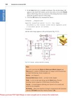
1. Fig. 11.14 is an exploded orthographic projection of the parts of a pis-
ton and its connecting rod. There are four parts in the assembly. Small
drawings of the required sheet set are shown in Fig. 11.16.
Construct the drawing in Fig. 11.14 and also the four drawings of
its parts. Save each of the drawings in a Layout1 format and construct
the sheet set which contains the five drawings.
Ch11-H8512.qxd 4/4/07 6:48 PM Page 183
Construct the DWF file of the sheet set. Experiment sending it to a
friend via email as an attachment to a document, asking him/her to
return the whole email to you without changes. When the email is
returned, open its DWF file and click each drawing icon in turn to
check the contents of the drawings.
Note
Fig. 11.15 shows a DWF for the sheet set from exercise 1 with the addi-
tion of a sixth drawing which is a 3D exploded model drawing of the
184 Introduction to AutoCAD 2008
Fig. 11.14 Exercise 1 – the
exploded orthographic projection
Fig. 11.15 The DWF for exercise 1
Ch11-H8512.qxd 4/4/07 6:48 PM Page 184
five parts of the piston and connecting rod which has been Gourand
shaded – see Chapter 16. This illustration has been included here to
show that such shaded 3D models can be included in a sheet set.
2. Construct a similar sheet set as in the answer to Exercise 1 from the
exploded orthographic drawing of a Machine adjusting spindle given
in Fig. 11.17.
Sheet sets 185
Dimensions in millimetres
DO NOT SCALE
DO NOT SCALE
DO NOT SCALE
DO NOT SCALE
Dimensions in millimetres
Dimensions in millimetres
Dimensions in millimetres
Holes ∅10
Hole ∅20
Hole ∅20
Hole ∅10
Hole ∅20
∅70
83
58
45
Cham 2×2
30
M10
35
R10
Sphere ∅40
Sphere ∅64
Sphere ∅64
Sphere ∅40
Sphere ∅64
M10
45
30
23
20
23
20
25
8
25
8
∅70
20 20
150 70
63
58
150
20
35
R15
R8
R10
DO NOT SCALE
A. READER
A. Reader
A. Reader
A. Reader
A. Reader
Scale 11
Scale 1:1
Scale 1:1
Scale 1:1
Scale 1:1
Date: 23.6.2007
Date: 23.6.2007
Date: 23.06.2007
Date: 23.06.2007
Date: 23.06.2007
Part: 8/45+8/46
Part: 8/46
Part: 8/48
Part: 8/46
Parts: 8/46 & 8/47 BOLT & PIN
PISTON & CONNECTING ROD
R20
Pin 70
× ∅20
Pin 70×∅20
Fig. 11.16 Exercise 1 – the five
drawings in the sheet set
1
2
4
Part No. Name of part
MACHINE ADJUSTING SPINDLE
1 SPINDLE AND PIN
2 SHOULDER WASHERS
3 BRACKET
4 LOCKSCREW
5 WASHER
6 HANDLE
35
6
130
8
24
6
80
12
40
18
5
M6
25
AA
28
40°
7
R6
R12
100
Tapped M10
Hole ∅10
∅24
∅12
∅24
26
× ∅3
∅90
∅30
10
45
15 15
12
Fig. 11.17 Exercise 2
Ch11-H8512.qxd 4/4/07 6:48 PM Page 185
CHAPTER 12
Building drawing
Aim of this chapter
To show that AutoCAD 2008 is a suitable CAD software package for the
construction of building drawings.
Building drawings
There are a number of different types of drawings related to the construc-
tion of any form of building. As fairly typical examples of a set of building
drawings, in this chapter, seven drawings are shown related to the con-
struction of an extension to an existing two-storey house (44 Ridgeway
Road). These show:
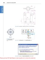
1. A site plan of the original two-storey house, drawn to a scale of 1:200
(Fig. 12.1).
2. A site layout plan of the original house, drawn to a scale of 1:100
(Fig. 12.2).
186
Fences
Summers Road
Meeting
Hall
Car park
Ridgeway Road
Scale:
Title:
Date: Drawing No:
44 Ridgeway Road
1:200 10:03:08 1
Site plan
Fig. 12.1 A site plan
Ch12-H8512.qxd 4/4/07 6:49 PM Page 186
Building drawing 187
Scale:
Title:
Date: Drawing No:
44 Ridgeway Road
Ridgeway Road
MH
MH
8.50 m
6.00 m
13.00 m
5.75 m
Summers Road
1:100 11:03:08 2
Site layout
Fig. 12.2 A site layout plan
3. Floor layouts of the original house, drawn to a scale of 1:50
(Fig. 12.3).
8.50 m
5.75 m
Scale:
Title:
Date: Drawing No:
44 Ridgeway Road
FIRST FLOOR
GROUND FLOOR
SITTING
ROOM
SPARE
ROOM
BEDROOM 1
BEDROOM 2
BED 3
KITCHEN
HALL
UTILITY
ROOM
WC
1:50 14:03:08 3
Floor layouts
Fig. 12.3 A floor layouts drawing
of the original house
Ch12-H8512.qxd 4/4/07 6:49 PM Page 187
188 Introduction to AutoCAD 2008
5. Floor layouts including the proposed extension, drawn to a scale of
1:50 (Fig. 12.5).
Scale:
Title:
Date: Drawing No:
44 Ridgeway Road
EastSouth
North West
1:50 13:03:08 4
Views
Fig. 12.4 Views of the original
house
Scale:
Title:
Date:
Drawing No:
44 Ridgeway Road
BEDROOM 1 BEDROOM 4
BEDROOM 3BEDROOM 2
BATH
SPARE
ROOM
SITTING
ROOM
UTILITY
ROOM
DINING
ROOM
KITCHEN
NEW LAYOUT
GROUND FLOOR
NEW LAYOUT
FIRST FLOOR
HALL
WC
1:50
17:03:08
5
Revised floor layouts
3.25 m
Fig. 12.5 Floor layouts drawing of
the proposed extension
6. Views of all four sides of the house including the proposed extension,
drawn to a scale of 1:50 (Fig. 12.6).
4. Views of all four sides of the original house drawn to a scale of 1:50
(Fig. 12.4).
Ch12-H8512.qxd 4/4/07 6:49 PM Page 188
Building drawing 189
Scale:
Title:
Date: Drawing No:
44 Ridgeway Road
East
South
North
West
1:50 18:03:08 6
Revised views
Fig. 12.6 Views including the
proposed extension
7. A sectional view through the proposed extension, drawn to a scale of
1:50 (Fig. 12.7).
Scale:
Title:
Date:
Drawing No:
44 Ridgeway Road
1:50
20:03:08
7
Section through revision
Fig. 12.7 A section through the
proposed extension
Notes
1. Other types of drawings will be constructed which show the details of
parts such as doors, windows, floor structures, etc. These are often
shown in sectional views.
2. Although the seven drawings related to the proposed extension of the
house at 44 Ridgeway Road are shown here as having been con-
structed on either A3 or A4 layouts, it is common practice to include
several types of building drawings on larger sheets such as A1 sheets
of a size 820 mm ϫ 594 mm.
Ch12-H8512.qxd 4/4/07 6:49 PM Page 189
190 Introduction to AutoCAD 2008
wall
partition
compass
MH
bath
sink
basin
cooker
frig
WC
boiler
stair
window02window01
up_and_over
rainwater
runway
door02 door01
tree01
tree02
C
R
B
Fig. 12.8 A small libray of building
symbols
Pavement
Existing
bungalow
Fence
Garage
7
m × 2.5 m
Bathroom
3.5
m × 2 m
Kitchen
5 m
× 2.5 m
Lounge
7
m × 4 m
Bed 1
3.5
m ×
3.5
m
Bed 2
3.5 m
×
3.5
m
WC
21 m
1 m
12.5 m
7 m
15 m
Fig. 12.9 Exercise 1
Floor layouts
When constructing floor layout drawings it is advisable to build up a library
of block drawings of symbols representing features such as doors, win-
dows, etc. These can then be inserted into layouts from the DesignCenter.
A suggested small library of such block symbols is shown in Fig. 12.8.
Revision notes
There are a number of different types of building drawings – site plans,
site layout plans, floor layouts, views, sectional views, detail drawings,
etc. AutoCAD 2008 is a suitable CAD program to use when constructing
building drawings.
Exercises
1. Fig. 12.9 is a site plan drawn to a scale of 1:200 showing a bungalow
to be built in the garden of an existing bungalow.
Construct the library of symbols shown in Fig. 12.8 and by inserting
the symbols from the DesignCenter construct a scale 1:50 drawing of
the floor layout plan of the proposed bungalow.
Ch12-H8512.qxd 4/4/07 6:49 PM Page 190
Building drawing 191
6.500 m 12.000 m
1.500 m
5 m
7.000 m
3.000 m
100°
83°
3 m
4.5 m
11.000 m
Boundary fence 34 m long
Step
Step
Parchment Road
Boundary fence 28m long
Boundary fence 19 m long
OUT-
HOUSE
HOUSE
Fig. 12.10 Exercise 2
2. Fig. 12.10 is a site plan of a two-storey house to be built on abuilding
plot. Design and construct to a scale 1:50, a suggested pair of floor
layouts for the two floors of the proposed house.
3. Fig. 12.11 showsascale 1:100 site plan for the proposed bungalow at
4 Caretaker Road. Construct the floor layout for the proposed house
shown in the drawing in Fig. 12.12.
Dimensions in metres
A. STUDENT SCALE 1:100
PLOT 4
Caretaker Road
Soakaway
SITE PALN – PLOT 4 CARETAKER ROAD
9.000
8.000
5.700
9.000
MH
MH
MH
Fig. 12.11 Exercise 3 – site plan
Ch12-H8512.qxd 4/4/07 6:49 PM Page 191
192 Introduction to AutoCAD 2008
4.000
9.000
4.000
4.0004.000
KITCHEN
BATH
& WC
BEDROOM
2
BEDROOM
1
LIVING
ROOM
SCALE 1:50
A. STUDENT BUILDING PLAN PLOT 4 CARETAKER ROAD
Fig. 12.12 Exercise 3
Ch12-H8512.qxd 4/4/07 6:49 PM Page 192
PART II
3D Design
Ch13-H8512.qxd 4/4/07 6:50 PM Page 193
Ch13-H8512.qxd 4/4/07 6:50 PM Page 194
This page intentionally left blank
CHAPTER 13
Introducing 3D modelling
Aims of this chapter
1. To introduce the tools used for the construction of 3D solid models.
2. To give examples of the construction of 3D solid models using tools
from the 3D Make control panel.
3. To give examples of 2D outlines suitable as a basis for the construction
of 3D solid models.
4. To give examples of constructions involving the Boolean operators –
Union, Subtract and Intersect.
Introduction
As shown in Chapter 1 the AutoCAD coordinate system includes a third
coordinate direction Z, which, when dealing with 2D drawings in previ-
ous chapters, has not been used. 3D model drawings make use of this
third Z coordinate.
The 3D Modeling workspace
It is possible to construct 3D model drawings in the AutoCAD Classic
or 2D Drafting & Annotation workspaces, but in this part of the book
we will be working in the 3D Modeling workspace in the template
acadiso3D.dwt. To set this workspace left-click New in the File drop-
down menu (Fig. 13.1) and from the Select template dialog click
acadiso3D in the Name list (Fig. 13.2). The acadiso3D template
appears (Fig. 13.3). In this window the seven main 3D control panels
of the DASHBOARD are shown. It is not necessary to have the
DASHBOARD on screen. It is up to the operator to decide which of
the available methods of calling tools for 3D modelling they wish to
use – control panels, toolbars, entering tool names or abbreviation or
from drop-down menus.
The acadiso3D window in Fig. 13.3 shows the grid in a Parallel
layout, brought about by a click on the Parallel Projection icon in the 3D
Navigate control panel. This is the window in which the examples in this
chapter have been constructed.
195
Fig. 13.1 Selecting New from
the File drop-down menu
Ch13-H8512.qxd 4/4/07 6:50 PM Page 195
196 Introduction to AutoCAD 2008
Fig. 13.2 Selecting acadiso3D
from the Select template dialog
Fig. 13.3 The acadiso3D template
screen showing seven of the 3D
control panels
Methods of calling tools for 3D modelling
When calling the tools for the construction of 3D model drawings, the
five same methods apply as that used when constructing 2D drawings:
1. A click on a tool icon in the 3D Make control panel.
2. A click on a tool icon in the Modeling toolbar.
Ch13-H8512.qxd 4/4/07 6:50 PM Page 196
Introducing 3D modelling 197
3. A click on the name of a tool from a drop-down menu brings the tool
into action.
4. Entering the tool name at the command line in the command window,
followed by pressing the Return button of the mouse or the Return
key of the keyboard, brings the tool into action.
5. Some of the 3D tools have an abbreviation which can be entered at the
command line instead of its full name.
Fig. 13.4 shows the tools and tooltips in the 3D Make control panel.
Notes
1. As when constructing 2D drawings, no matter which method is used –
most operators will use a combination of these five methods – the
result of calling a tool results in prompts sequences appearing at the
command prompt as in the following example:
Command: enter box right-click
Specify first corner or [CEnter]: enter 90,120 right-click
Specify other corner or [Cube/Length]:
Fig. 13.4 The tool icons and
tooltips in the 3D Make control
panel
Ch13-H8512.qxd 4/4/07 6:50 PM Page 197
198 Introduction to AutoCAD 2008
Fig. 13.5 Selecting To p from the
3D Navigate control panel’s
popup list
Or, if the tool is called from its tool icon or from a drop-down menu:
Command:_box
Specify first corner or [CEnter]: enter 90,120 right-click
Specify other corner or [Cube/Length]:
2. In the following pages, if the tool’s sequences are to be repeated, they
may be replaced by an abbreviated form such as:
Command:_box
[prompts]: 90,120
[prompts]:
The Polysolid tool (Fig. 13.6)
1. Make a new layer Construct of colour black. Make this layer current.
2. Click Top in the 3D Navigate control panel’s popup list (Fig. 13.5).
3. Construct an octagon of edge length 60 using the Polygon tool.
4. Set layer 0 current and from the 3D Navigate drop-down menu select
Southeast Isometric.
5. Call the Polysolid tool with a click on its tool icon in the 3D Make
control panel (Fig. 13.4). The command line shows:
Command:_Polysolid Height ϭ 0, Width ϭ 0, Justification ϭ Center
Specify start point or [Object/Height/Width/Justify]ϽObjectϾ:
enter h (Height)
Specify height Ͻ4Ͼ: 60
Height ϭ 60, Width ϭ 0, Justification ϭ Center
Specify start point or [Object/Height/Width/Justify] ϽObjectϾ:
enter w (Width)
Ch13-H8512.qxd 4/4/07 6:50 PM Page 198
Introducing 3D modelling 199
Fig. 13.6 Example – Polysolid
Outline constructed
using Line tool
Line outline changed
to a region
2010020
20 2060
Fig. 13.7 First example – Line
outline and Region
Specify width Ͻ0Ͼ: 5
Height ϭ 60, Width ϭ 5, Justification ϭ Center
Specify start point or [Object/Height/Width/Justify]ϽObjectϾ:
Specify next point or [Arc/Undo]: pick one corner of octagon
Specify next point or [Arc/Undo]: pick second corner
Specify next point or [Arc/Close/Undo]: pick third
Specify next point or [Arc/Close/Undo]: pick fourth
Specify next point or [Arc/Close/Undo]: pick fifth
Specify next point or [Arc/Close/Undo]: pick sixth
Specify next point or [Arc/Close/Undo]: pick seventh
Specify next point or [Arc/Close/Undo]: pick last
Specify next point or [Arc/Close/Undo]: enter c (Close)
Command:
And the Polysolid forms (Fig. 13.6).
2D outlines suitable for 3D models
When constructing 2D outlines suitable as a basis for constructing some
forms of 3D model, use tools from the 2D Draw control panel. If con-
structed using tools such as Line, Circle and Ellipse, before being of any
use for 3D modelling, outlines must be changed into regions with the
Region tool (2D Draw control panel – Fig. 13.8). Closed polylines can be
used without the need to use the Region tool.
First example – Line outline and Region (Fig. 13.7)
1. Construct the left-hand drawing of Fig. 13.7 using the Line tool.
2. Left-click on Region tool in the 2D Draw control panel (Fig. 13.8), or
enter reg at the command line. The command line shows:
Command:_region
Select objects: window the drawing 12 found
Select objects: right-click
1 Region created
Command:
Ch13-H8512.qxd 4/4/07 6:50 PM Page 199
200 Introduction to AutoCAD 2008
R25
30
60
1060
70
After Union
Subtract
region
from
Union
Union of
2 regions
3
4
2
1
Fig. 13.9 Second example – Union,
Subtract and regions
Fig. 13.10 The Union, Subtract
and Intersect tool icons in the
3D Make control panel
Fig. 13.8 Selecting Region from a
flyout in the 2D Draw control
panel
And the Line outline is changed to a region – right-hand drawing of
Fig. 13.7.
Second example – Union, Subtract and regions (Fig. 13.9)
1. In the Top view, construct drawing 1 of Fig. 13.9 and with the Copy
tool (2D Draw control panel), copy the drawing three times to produce
drawings 2, 3 and 4.
2. With the Region tool change all the outlines into regions.
3. Drawing 2 – call the Union tool from the 3D Make control panel
(Fig. 13.10). The command line shows:
Command: _union
Select objects: pick the left-hand region 1 found
Select objects: pick the circular region 1 found, 2 total
Select objects: pick the right-hand region 1 found, 3 total
Command:
4. Drawing 3 – with the Union tool form a union of the left-hand region
and the circular region.
5. Drawing 4 – call the Subtract tool (Fig. 13.10). The command line
shows:
Command:_subtract Select solids and regions to subtract from
Select objects: pick the region just formed 1 found
Ch13-H8512.qxd 4/4/07 6:50 PM Page 200
Introducing 3D modelling 201
Select objects: right-click
Select solids and regions to subtract: pick the right-hand region 1
found
Select objects: right-click
Command:
Third example – Intersection and regions (Fig. 13.11)
1. Construct drawing 1 of Fig. 13.11.
2. With the Region tool, change the three outlines into regions.
3. With the Copy tool, copy the three regions.
4. Drawing 2 – call the Intersect tool from the 3D Make control panel.
The command line shows:
Command:_intersect
Select objects: pick one of the circles 1 found
Select objects: pick the other circle 1 found, 2 total
Select objects: right-click
Command:
And the two circular regions are intersect with each other to form a
region.
5. Drawing 3 – repeat using the Intersect tool on the intersection of the
two circles and the rectangular region.
Circle centres 50 apart
123
Intersect on
the 2 circles
Intersect
with rectangle
50
90
R55
R55
Fig. 13.11 Third example –
Intersection and regions
The Extrude tool
The Extrude tool can be called either with a click on its tool icon in the
3D Make control panel (Fig. 13.4, page 197), or from the Modeling tool-
bar, or from the Draw drop-down menu, or by entering extrude or its
abbreviation ext at the command line.
Note
In this chapter 3D models are shown in illustrations as they appear in the
acadiso3D.dwt template screen. In later chapters, 3D models are sometimes
shown in outline only. This is to allow the reader to see the parts of 3D mod-
els in future chapters more clearly in the illustrations.
Ch13-H8512.qxd 4/4/07 6:50 PM Page 201
202 Introduction to AutoCAD 2008
Fig. 13.12 First example –
Extrude
Fig. 13.13 Second example –
Extrude
Examples of the use of the Extrude tool
The three examples of forming regions given in Figs. 13.7, 13.9 and 13.11
are used here to show results of using the Extrude tool.
First example – Extrude (Fig. 13.12)
From the first example of forming a region:
1. Call the Extrude tool. The command line shows:
Command: _extrude
Current wire frame density: ISOLINESϭ4
Select objects to extrude: pick region 1 found
Select objects to extrude: right-click
Specify height of extrusion or [Direction/Path/Taper angle] Ͻ45Ͼ:
enter 50 right-click
Command:
2. Select Southwest Isometric from the popup list in the 3D Navigate
control panel (Fig. 13.5, page 198). The extrusion appears in an iso-
metric view.
3. Call Zoom and zoom to 1.
Notes
1. In the above example we made use of one of the isometric views possi-
ble from the 3D Navigate control panel (Fig. 13.5). These views will
be used frequently in examples to show 3D solid model drawings in a
variety of positions in 3D space.
2. Note the Current wire frame density: ISOLINESϭ4 in the prompts
sequence when Extrude is called. The setting of 4 is suitable when
extruding plines or regions consisting of straight lines, but when arcs
are being extruded it may be better to set ISOLINES to a higher figure
as follows:
Command: enter isolines right-click
Enter new value for ISOLINES Ͻ4Ͼ: enter 16 right-click
Command:
Second example – Extrude (Fig. 13.13)
From the second example of forming a region:
1. Set ISOLINES to 16.
2. Call the Extrude tool. The command line shows:
Command: _extrude
Current wire frame density: ISOLINESϭ16
Select objects to extrude: pick the region 1 found
Select objects to extrude: right-click
Specify height of extrusion or [Direction/Path/Taper angle]: enter t
right-click
Ch13-H8512.qxd 4/4/07 6:50 PM Page 202