Learning AutoCAD 2010, Volume 1 phần 6 doc
Bạn đang xem bản rút gọn của tài liệu. Xem và tải ngay bản đầy đủ của tài liệu tại đây (7.49 MB, 46 trang )
Lesson: Creating Object Patterns ■ 217
Array Dialog Box: Polar Array
Click to select the object(s) to include in the array.
Enter the center point's coordinates in the X and Y fields or click the Select Point icon to select a center
point in the drawing window.
Select the method for calculating the polar array.
■ Total number of items and angle to fill.
■ Total number of items and angle between items.
■ Angle to fill and angle between items.
Enter the total number of items for the array. This includes the original object.
Enter the total angle for the array. A negative number creates the array in a clockwise direction.
Select to rotate each object as it is placed in the array.
Zooming while using the Array command
Although you cannot zoom or pan the drawing using traditional methods while the Array
dialog box or Array Preview is active, you can select the Pick Object button, or any of
the other pick point buttons to temporarily hide the dialog box, allowing you to zoom
and pan. To return to the Array dialog box, press ENTER without selecting any objects or
points.
218 ■ Chapter 3: Manipulating Objects
Procedure: Creating a Rectangular Array of Objects
The following steps give an overview of creating rectangular arrays.
1.
On the ribbon, click Home tab > Modify Panel > Array.
2.
In the Array dialog box, click the Rectangular option. Click Select Objects and select the objects to
include in the array.
3.
Enter row and column values, or click Pick Offset to define the row and column offset values.
4.
If required, enter an angle for the array.
5.
Click Preview to preview the array.
6.
Right-click to accept and create the array, or press ESC to return to the dialog box.
Lesson: Creating Object Patterns ■ 219
Procedure: Creating a Polar Array of Objects
The following steps are an overview of creating polar arrays.
1.
On the ribbon, click Home tab > Modify Panel > Array.
2.
In the Array dialog box, click the Polar option. Click Select Objects and select the objects to include in
the array.
3.
In the Center Point fields, enter the X and Y coordinates for the center point of the array, or click Pick
Center Point to select the center point in the drawing.
4.
In the Method list, select the method to use for the array.
5.
Enter values in the appropriate fields according to the method that you chose.
6.
Click Preview to preview the array.
7.
Right-click to accept and create the array, or press ESC to return to the dialog box.
220 ■ Chapter 3: Manipulating Objects
Guidelines for Rectangular Versus Polar Array
Follow these guidelines when using the Array command:
■ To create many regularly spaced objects,the Arraycommand isfaster than Copy command.
■ For rectangular array, specify the number of rows and columns and the distance between each.
■ For Polar Array, specify the number of copies of the object, the angle to fill, and whether the
copies are rotated.
■ Specify the center point about which the objects will array.
■ A Polar Array is drawn counterclockwise or clockwise, depending on whether you enter a positive
or a negative value for the angle to fill.
Lesson: Creating Object Patterns ■ 221
Practice Exercise: Creating an Array of Objects
In this practice exercise, you draw a 1 x 1 rectangle
and create an array using the Polar and Rectangular
array options.
1.
Begin by drawing the rectangle:
■ Start the Rectangle command.
■ Click the first corner in the drawing
window.
■ For the other corner enter D (for
Dimensions). Press ENTER.
■ Enter a length of 1 and a width of 1.
■ Click to position the rectangle.
2.
To create a polar array:
■ On the Home tab, click Modify panel >
Array.
■ In the Array dialog box, click Polar Array (1).
■ Click the Select objects button (2) and
select the rectangle. Press ENTER to return
to the dialog box.
■ Click the Center point button (3) and, using
object snap tracking, track a center point
that is two units down from the midpoint
of the rectangle as shown.
■ For Total number of items (4), enter 6.
■ For Angle to fill (5), enter 360.
■ Click OK (6).
■ Zoom to display your polar array, which
should resemble the following illustration.
222 ■ Chapter 3: Manipulating Objects
3.
To create a rectangular array:
■ Create another 1 x 1 rectangle.
■ On the Home tab, click Modify panel >
Array.
■ In the Array dialog box, click Rectangular
Array (1).
■ Click the Select objects button (2), and click
the rectangle. Press ENTER to return to the
dialog box.
■ Enter 12 for Rows (3) and Columns (4).
■ Enter 2 for Row offset (5) and Column
offset (6).
■ Click OK (7).
■ Zoom to display your rectangular array,
which should resemble the following
illustration.
Lesson: Creating Object Patterns ■ 223
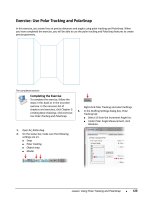
Exercise: Array Objects in the Drawing
In this exercise, you create polar and rectangular
arrays of various pieces of office furniture in an office
floor plan. When you have completed the exercise,
you will be able to use the Array command to create
arrays of objects in your drawings.
You have the option of completing this
exercise using either imperial or metric
units. Select one version of the exercise
to complete the steps.
The completed exercise
Completing the Exercise
To complete the exercise, follow the
steps in this book or in the onscreen
exercise. In the onscreen list of
chapters and exercises, click Chapter
3: Manipulating Objects. Click Exercise:
Array Objects in the Drawing Metric.
Exercise: Array Objects in the Drawing
(Metric Units)
1.
Open M_Creating-Arrays.dwg.
2.
To create a polar array, zoom into the area
shown in the following image.
3.
To create an array of the chair around the
table:
■ On the Home tab, click Modify panel >
Array.
■ In the Array dialog box, click Polar Array (1).
■ Click Select Objects (2). Select the chair.
■ Press ENTER to return to the dialog box.
224 ■ Chapter 3: Manipulating Objects
■ Click the Center point button (3).
■ With Object Snap on, select the center of
the table.
■ For the total number of items (4), enter 6.
■ For the angle to fill (5), enter 360.
■ Click Preview (6).
■ Do not press ENTER. Press ESC to return to
the dialog box.
4.
Change the total number of items:
■ In the Array dialog box, enter 8 for the total
number of items (4).
■ Click OK to complete the polar array.
■ Eight chairs are arrayed around the table as
in the following illustration.
5.
Zoom to display the area that is indicated in
the following image. Make certain that the
walls are visible.
6.
Use the Rectangular array option to populate
the remaining offices with the objects from the
first two:
■ On the Home tab, click Modify panel >
Array.
■ In the Array dialog box, click Rectangular
Array.
■ Click the Select Objects button.
■ Select the objects indicated in the following
image. Press ENTER.
Note: Use two separate crossing windows to
select the objects.
7.
Set your desired number of rows and columns:
■ In the Array dialog box, for Rows, enter 4.
■ For Columns, enter 2.
■ Under Offset Distance and Direction, click
the button indicated below to Pick Both
Offsets.
Lesson: Creating Object Patterns ■ 225
8.
Specify the unit cell as indicated:
■ Click the endpoint of the line of the lower
interior wall.
■ For the other corner, click the endpoint of
the line of the upper interior wall.
■ Click Preview.
■ Your rectangular array should appear as
illustrated.
■ Do not press ENTER.
■ Use the wheel on the mouse to adjust the
display of your drawing.
■ If necessary, press ESC to return to the
dialog box and reselect the unit cell,
or press ENTER to complete the Array
command.
9.
Close all files. Do not save.
Exercise: Array Objects in the Drawing
(Imperial Units)
1.
Open I_Creating-Arrays.dwg.
2.
To create a polar array, zoom into the area
shown in the following image.
3.
To create an array of the chair around the
table:
■ On the Home tab, click Modify panel >
Array.
■ In the Array dialog box, click Polar Array (1).
■ Click Select Objects (2). Select the chair.
■ Press ENTER to return to the dialog box.
226 ■ Chapter 3: Manipulating Objects
■ Click the Center point button (3).
■ With Object Snap on, select the center of
the table.
■ For the total number of items (4), enter 6.
■ For the angle to fill (5), enter 360.
■ Click PREVIEW (6).
■ Do not press ENTER. Press ESC to return to
the dialog box.
4.
Change the total number of items:
■ In the Array dialog box, enter 8 for the total
number of items (4).
■ Click OK to complete the polar array.
■ Eight chairs are arrayed around the table as
in the following illustration.
5.
Zoom to display the area that is indicated in
the following image. Make certain the walls are
visible.
6.
Use the Rectangular array option to populate
the remaining offices with the objects from the
first two:
■ On the Home tab, click Modify panel >
Array.
■ In the Array dialog box, click Rectangular
Array.
■ Click the Select objects button.
■ Select the objects that are indicated in the
following image. Press ENTER.
Note: Use two separate crossing windows to
select the objects.
7.
Set your desired number of rows and columns:
■ In the Array dialog box, for Rows, enter 4.
■ For Columns, enter 2.
■ Under Offset Distance and Direction, click
Pick Both Offsets.
Lesson: Creating Object Patterns ■ 227
8.
Specify the unit cell as indicated:
■ Click the endpoint of the line of the lower
interior wall.
■ For the other corner, click the endpoint of
the line of the upper interior wall.
■ Click PREVIEW.
■ Your rectangular array should appear as
illustrated.
■ Do not press ENTER.
■ Use the wheel on the mouse to adjust the
display of your drawing.
■ If necessary, press ESC to return to the
dialog box and reselect the unit cell,
or press ENTER to complete the Array
command.
9.
Close all files. Do not save.
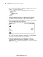
228 ■ Chapter 3: Manipulating Objects
Lesson: Changing an Object's Size
This lesson describes how to increase or decrease the size of objects in the drawing using the Scale
command.
When you create drawings, it is often quicker to modify existing geometry then to create new
geometry from scratch. With the Scale command, you can resize geometry to meet the current design
requirements.
The object on the right was created by scaling the object on the left by .5.
Objectives
After completing this lesson, you will be able to:
■ Use the Scale command or grips to scale objects in the drawing.
Lesson: Changing an Object's Size ■ 229
Scaling Objects
You use the Scale command when you need to change the size of existing geometry in the drawing.
The Scale command can scale an entire drawing or just the objects that you select. After you select the
geometry to be scaled, you have the option of scaling a copy of the selected geometry. If you choose
this option, the original geometry remainsunchanged while a copy of the geometry is scaled by the
factor you specify. You can also control a scaling operation using grips.
Command Access
Scale
Command Line:
SCALE, SC
Ribbon: Home tab > Modify panel > Scale
Note: Do not confuse this command with the 3D Scale command.
Menu Bar: Modify > Scale
Shortcut Menu: Select objects then right-click anywhere in the drawing window. Click Scale.
230 ■ Chapter 3: Manipulating Objects
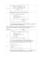
Command Options
With the Scale command, you can scale geometry using the following options.
Option
Description
Base Point
Use this option to define the point from which the selected geometry is scaled. If the
base point is not coincident with the selected geometry, the distance between the
base point and the geometry is scaled.
Copy
Use this option to scale a copy of the selected geometry. The original geometry is not
scaled.
Reference
Use this option to specify a reference length, either by entering a value, or selecting
two points. After you specify the reference length, enter a new length for the
reference length. The scale factor is calculated as Reference Length = New Length.
Procedure: Scaling Objects
The following steps give an overview of scaling objects using the Scale command.
1.
On the ribbon, click Home tab > Modify panel > Scale.
2.
Select the objects to be scaled. Press ENTER to end the object selection.
3.
Select a base point.
4.
Enter a scale factor. Press ENTER.
Lesson: Changing an Object's Size ■ 231
Procedure: Scaling Objects Using Grips
The following steps give an overview of using grips to scale objects.
1.
Select an object to activate its grips.
2.
Click a grip to activate grip edit mode. By default, this point will also be used as the base point for the
scale.
3.
Right-click anywhere in the drawing. Click Scale.
4.
Specify a scale factor.
Guidelines for Scaling Objects
■ A value less than 1 decreases the size of the geometry. A value greater than 1 increases the size of
the geometry. For example, entering a scale factor of .5 halves the size of the selected objects.
■ The most recent scale factor used persists for the current editing session.
■ To scale using the Reference option, use object snap to click two points on the object to define the
reference scale. This is often quicker and more accurate than finding the distance and calculating a
scale factor.
■ When you use the Reference option, the two points that define the reference distance are
independent from the scale base point.
232 ■ Chapter 3: Manipulating Objects
Practice Exercise: Scaling Objects
In this practice exercise, you draw an object and
scale it using the Scale command with the Reference
option and grips with the Copy option. You draw a
rectangle of any size and scale it to a specific size.
Then you scale and copy it using grips
1.
Draw a rectangle of any size:
■ Start the Rectangle command.
■ Click the first corner.
■ Click the opposite corner.
2.
To scale the rectangle using the Reference
scale option:
■ On the Home tab, click Modify panel >
Scale.
■ Select the rectangle. Press ENTER.
■ Click a basepoint on or near the rectangle.
■ Right-click and click Reference.
■ To specify the reference length, select the
object snap endpoints as indicated below.
Notice that the software calculates the
exact length of the line based on the two
endpoints that you select.
■ To specify a new length, enter 2 and press
ENTER.
3.
Use grips to scale and copy the rectangle at .5
scale and then at .25 scale of the original size.
Select the middle of the rectangle for the
basepoint:
■ With the command line blank, select the
rectangle.
■ Right-click any grip on the rectangle. Click
Scale.
■ Using object snap tracking, select the
middle of the rectangle for the basepoint.
Lesson: Changing an Object's Size ■ 233
4.
To specify the scale factors:
■ Enter .5. Press ENTER.
■ Enter .25. Press ENTER.
■ Press ESC to end the scale procedure.
■ Press ESC to clear the rectangle selection.
Your drawing should look similar to the
illustration below.
234 ■ Chapter 3: Manipulating Objects
Exercise: Scale Objects Using the Copy Option
In this exercise, you use the Copy option of the
Scale command to scale a copy of the link-arm
profile geometry and leave the source geometry
unchanged. You then rotate the original geometry
and dimensions.
The completed exercise
Completing the Exercise
To complete the exercise, follow the
steps in this book or in the onscreen
exercise. In the onscreen list of
chapters and exercises, click Chapter
3: Manipulating Objects. Click Exercise:
Scale Objects Using the Copy Option.
1.
Open M_Scale-Copy.dwg.
2.
On the Home tab, click Modify panel > Scale.
Window select all of the geometry and
dimensions in the drawing.
3.
Press ENTER to accept the selection.
4.
Select the center of the large circle as the base
point.
5.
Right-click anywhere in the drawing. Click
Copy.
6.
Enter 1.25 for the scale factor. Press ENTER.
7.
To rotate the original objects:
■ Begin the Rotate command.
■ Enter P. Press ENTER to select the previous
selection set.
8.
Press ENTER to accept the selection set.
Lesson: Changing an Object's Size ■ 235
9.
Select the center point of the larger circle.
10.
Enter 90. Press ENTER.
11.
Close all files. Do not save.
236 ■ Chapter 3: Manipulating Objects
Challenge Exercise: Grips
In this exercise, you use grips to edit and manipulate objects in a drawing. When you have completed
the exercise, you will be able to use grips to effectively manipulate geometry without having to use
the standard editing commands.
The completed exercise
Completing the Exercise
To complete the exercise, follow the steps in this book or in the onscreen exercise.
In the onscreen list of chapters and exercises, click Chapter 3: Manipulating Objects.
Click Challenge Exercise: Grip Edit Objects.
1.
Open M_Grips-Exercise.dwg.
2.
To move a door into position using grips:
■ Select the door.
■ Click the single grip to make it a selected grip.
■ Right-click. Click Move.
■ Drag the door into position. Click the endpoint of the wall. Your object will still be selected.
Challenge Exercise: Grips ■ 237
3.
To copy the door using grips for the next room:
■ Click the grip again to make it a selected grip.
■ Right-click. Click Move.
■ Right-click. Click Copy.
Note: With a single object, you do not need to click Move first and can proceed to Copy. With more
than one object selected, you always need to click Move before clicking Copy.
■ Drag the door one room to the right. Click the endpoint of the wall.
■ Press ENTER to complete the copy.
■ Press ESC to release your selection.
4.
To move the plant into position using grips:
■ Select the plant.
■ Click the grip to make it selected.
■ Right-click. Click Move.
■ Drag the plant to the upper-left corner as shown below.
238 ■ Chapter 3: Manipulating Objects
5.
To copy the plant using grips:
■ Click the plant grip again to make it selected.
■ Right-click. Click Move.
■ Right-click. Click Copy.
■ Drag and place the second plant in the lower-right corner as shown.
■ Press ENTER to finish the copy.
■ Press ESC to clear your selection.
6.
To move the credenza and keyhole desk using grips:
■ Using the Move grip mode, drag the credenza into position as shown.
■ Using the Move grip mode, drag the keyhole table into position as shown.
Challenge Exercise: Grips ■ 239
7.
To move the file cabinet into position using grips:
■ Select the file cabinet.
■ Click the grip to select it.
■ Right-click. Click Move.
■ Drag the object to the lower-left corner as shown below. Place the object about four units above
the lower wall attached to the left side wall.
8.
To rotate the file cabinet using grips:
■ Click the grip again to select it.
■ Right-click. Click Rotate.
■ Enter 90. Press ENTER.
■ Press ESC to clear your selection set.
240 ■ Chapter 3: Manipulating Objects
9.
Use the Move and Rotate grip modes again to place the computer and phone onto the desk as shown.
Refer to the previous step if needed for the step-by-step process.
■ The computer object is rotated 45 degrees.
■ The phone object is rotated 90 degrees.
10.
Use Move, Rotate, and Copy grip modes to place the chair object in the office as shown:
■ The desk chair is rotated -45 degrees and the conference table chair is rotated at 45 degrees. The
remaining two chairs are rotated at 90 degrees.
Your office layout should look like the following image.
Challenge Exercise: Grips ■ 241
11.
Use the Copy and Base Point grip modes to copy many objects at once to populate the next office area
to the right:
■ Select all of the objects as shown in the following image.
■ Pick any one of the available grips to make it hot.
■ Right-click. Click Move.
■ Right-click. Click Copy.
■ Right-click. Click Base Point.
■ Pick the inside top-left corner of the room (1) for the base point.
■ Pick the top-left inside corner of the next room (2) for the move point.
■ Press ENTER to complete the copy.
■ Press ESC to release your selection set.