Learning AutoCAD 2010, Volume 2 phần 3 pot
Bạn đang xem bản rút gọn của tài liệu. Xem và tải ngay bản đầy đủ của tài liệu tại đây (9.29 MB, 37 trang )
Lesson: Editing Text ■ 67
Editing Text
There are five tools that you can use to edit text. These are:
■ Multiline Text Editor ribbon
■ In-place text editor
■ Properties palette
■ Quick Properties
■ Grips
The quickest way to edit text is to double-click the text object. If you double-click a multiline text
object, the Multiline Text Editor is displayed in the ribbon along with the In-Place Text Editor. If you
double-click a single line text object, the In-Place Text Editor opens where you can edit the text in the
same way you created it.
You can use the Quick Properties or the Properties palette to edit the properties associated with text
as well as the content of the text object. You can also use grips to edit the text's position and width.
When you select text once, grips are displayed. You can grip edit text objects using the same methods
as grip editing geometry.
In addition to the Multiline Text Editor, the in-place text editor offers real-time spell checking.
68 ■ Chapter 7: Annotating the Drawing
Command Access
Multiline Text Edit
Double-click Multiline Text
Command Line: MTEDIT, DDEDIT, ED
Ribbon: double-click Multiline Text Multiline Text tab > Text Editor panels
Menu Bar: Modify > Object > Text > Edit
Command Access
Single Line Text Edit
Double-click Single Line Text
Command Line: DDEDIT, ED
Menu Browser: Modify > Object > Text > Edit
Spell Check the Entire Drawing
You can check for spelling errors in the entire drawing or selected text objects. Type
spell at the command line and use the options in the dialog box.
Lesson: Editing Text ■ 69
Procedure: Editing Multiline Text
The following steps give an overview of editing multiline text.
1.
Double-click the Multiline Text.
2.
Use the in-place text editor to edit text content or select text to format using the options located on the
ribbon.
3.
Use the Text Editor options found on the ribbon to format text selected from the in-place text editor to
insert symbols, line spacing, numbering, bullets, or change paragraph justification in the selected text.
4.
Double-click outside the text editor window to end the editing operation.
Editing MultilineText with the Quick Properties Palette
Another option for editing
text objects is to use the Quick
Properties palette. You can modify
most of the properties associated
with the text as well as the text
content.
In the example on the right, the
text justification option is being
changed to Middle center using the
Quick Properties palette.
70 ■ Chapter 7: Annotating the Drawing
Procedure: Editing Single Line Text
The following steps give an overview of editing single line text.
1.
Double-click the Single Line Text.
2.
Use the in-place text editor to edit the content in each single line of text. You can right-click to check
and correct misspelled words.
3.
Click outside the text editor window to end the editing operation.
Editing Single Line Text with the Quick Properties Palette
You can use the Quick Properties
palette to modify most of the
properties associated with single
line text as well as the text content.
In the example on the right, the
text rotation option has been
changed to 30 degrees using the
Quick Properties palette.
Lesson: Editing Text ■ 71
Exercise: Edit Text
In this exercise, you edit single line text and multiline
text to change the properties and create a numbered
list.
The completed exercise
Completing the Exercise
To complete the exercise, follow the
steps in this book or in the onscreen
exercise. In the onscreen list of
chapters and exercises, click Chapter 7:
Annotating the Drawing. Click Exercise:
Edit Text.
1.
Open M_Edit-Text.dwg.
2.
Zoom into the title block area of the drawing.
3.
Select the Arbor Press text to display the grip.
Note the location of the grip, indicating that
the text is left justified.
4.
If the Quick Properties palette is not open,
select it from the status bar or right-click to
access it from the shortcut menu:
■ Under Text, enter %%uArbor Press in the
Contents field.
Note: These are the ASCII characters for
underlining the text. If this were Multiline
Text you would be able to use the Formatting
options from the ribbon.
■ In the Justify list, select Middle.
■ In the Height field, enter 10.
5.
Press ESC to clear the selection. Note the new
appearance of the text.
6.
Zoom into the notes above the title block.
7.
Double-click the notes text. The Text
Formatting toolbar is displayed with the In-
Place Text Editor.
Click the beginning of each line and press DEL
to remove the numbers.
72 ■ Chapter 7: Annotating the Drawing
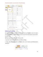
8.
Highlight all of the text beneath the word
Notes. On the ribbon, in the Paragraph panel,
click Numbering. Click Numbered.
The text should now appear as shown.
9.
Place the cursor at the beginning of line 3 and
press TAB.
The line is automatically renumbered as a
subnote and the numbers are reordered.
10.
Click Close Text Editor on the Close panel.
11.
Zoom to the extents of the drawing.
12.
Close all files without saving.
Lesson: Using Text Styles ■ 73
Lesson: Using Text Styles
This lesson describes how you can use text styles to control text appearance.
In a typical design environment, there can be several designers creating drawings. If each designer
were to choose their own text fonts for annotation, the resulting drawings would lack a uniform
appearance. Using text styles can help to create a consistent appearance across drawings by providing
predefined text formats.
Objectives
After completing this lesson, you will be able to:
■ Explain the purpose of text styles.
■ Create and use text styles.
74 ■ Chapter 7: Annotating the Drawing
Text Styles
Text styles provide an easy way for you to control the default appearance of text. Each text object
contains properties such as font, height, width factor and oblique angle. Using text styles, you can
predefine each of these properties, resulting in a uniform appearance of text objects that use the
same style.
Another benefit of using text styles is that you can update all text in the drawing that uses a certain
style simply by changing the style.
The following image illustrates the effect of changing a text style when it is being referenced by text
objects. In the floor plan on the right, the text style uses a smaller font so that the text objects better
fit the space.
Text Styles Defined
A text style is a collection of common text properties used by one or more text objects in the drawing.
You generally create several text styles. For example, you could have a text style for dimensions,
another for view labels, and another for title blocks or general drawing annotation.
Example of Text Styles
On a typical drawing, you might have one style defined for all of your general notes, text and
dimensions, another style for object labels, and another style for the title block information.
Text Style Key Points
■ A text style is a collection of predefined text properties such as font, height, width factor, and
oblique angle.
■ You create text styles to keep a uniform appearance of text objects in the drawing.
■ You can update all text in the drawing that uses a certain style simply by changing the style.
■ You generally create several text styles for objects such as dimensions, view labels, your title block
or general drawing annotation.
Lesson: Using Text Styles ■ 75
Creating and Using Text Styles
You use the Style command to create and manage text styles. By default, all new drawings contain two
text styles, one named Standard and one named Annotative. Standard is the current text style for all
new drawings, unless you base a new drawing on a template that has another style set as the current
style.
Creating and Using Text Styles
Text styles are similar to layers in that they are used to organize objects in the drawing. You create a
Text Style and make it current so that the text you enter appears in that style. You can also change the
Text Style of selected text after it was placed in the drawing.
To create text styles, you use the Text Style dialog box. To switch from the current text style to another,
you can select a text style from the list on the Text panel the same way you can make a Layer current
from the Layer Control list. Similarly, you can assign a text style to selected text from the text style list.
Command Access
Style
Command Line: STYLE, ST
Ribbon: Annotate tab > Text panel > Text Style
Menu Bar: Format > Text Style
76 ■ Chapter 7: Annotating the Drawing
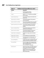
Text Style Dialog Box
You use the Text Style dialog box to create and manage text styles.
Use this area to view your current text Styles. You can also edit a selected style or rename it.
Select a Font Name from the list of available fonts. Apply a Font Style such as Bold or Italic if required.
Specify the size of your text in this section. If you choose to make your text Size Annotative, the Height
field changes to Paper Text Height. Enter the Paper Text Height you want to appear in all your layout
viewports for text created with this style regardless of the viewport scale.
Select any Effects to apply to the text such as Width Factor and Oblique Angle. A Width Factor of 1 is
normal. Less than 1 would make the text narrow and greater than 1 would make the text wide.
Applying Height to the Text Style
When you set the text height, it becomes the default value for text created with that
style. If this value is 0, you will be prompted to specify the text height each time you
create Single Line Text. When using the Multiline Text command, the text height can
be chosen or typed from the list in the Text panel.
Annotative Property
You can choose the Annotative Style (1) or assign the Annotative property (2) to a text style when
you want the text height to display and plot the same size in the drawing layout, regardless of the
viewport scale.
Lesson: Using Text Styles ■ 77
You can Match the text orientation to the layout (3) so that the text objects display horizontal if the
view is, for instance, isometric.
When Annotative is selected, the Height property changes to Paper Text Height (4). Enter a value
other than zero to set the height for all the text that utilizes this style. The text in the viewports is
automatically scaled to the paper height size in the drawing layout.
Example of Text Oriented to Layout
In the following images, two views are shown on the layout. In the first view, the text appears in the
same orientation that it was created, which is normal to the plan view and layout. In the second image,
the view was changed to isometric, but the text remains oriented to the layout.
Plan view
Isometric view
Setting Height in the Text Style
When you set a value for Height (Paper Text Height for annotative styles) in the text
style, it becomes the default value for all text created with that style. Then, when
you create a single line text object using the Text or Dtext commands, you are not
prompted for a paper height. Leave this option set to 0 if you want to be prompted
for the paper height when using the Text or Dtext commands.
78 ■ Chapter 7: Annotating the Drawing
Procedure: Creating and Using Text Styles
The following steps give an overview of creating and using text styles.
1.
Start the Style command.
2.
Select New (1) and enter a New Text Style Name (2).Click OK.
3.
Select the new style (1), assign a Font Name (2), a Height (3), Apply (4) and Set Current (5). Then Close
the dialog box.
4.
Begin the Text command.
Lesson: Using Text Styles ■ 79
5.
To change from one text style to another, choose the Text style from the list.
6.
To assign a Text Style to existing text objects:
■ With the Command Line blank, select the objects.
■ Select the text style from the list.
■ Press ESC to deselect the text objects.
Redefining Styles
If you redefine a style to be annotative or nonannotative, the objects that used
that style are not automatically updated. You can use the Annoupdate command to
update the objects to the new style, or change them using the Properties palette.
Text Style Guidelines
■ The default text style for all new drawings is Standard unless the new drawing is based on a
template with a different default style.
■ All text is assigned to a text style. If you do not create any new text styles, all text is assigned to the
Standard text style.
■ The default font for the Standard style is Arial.
■ You cannot delete or rename the Standard text style.
■ If you copy and paste text from another drawing or insert a block into a drawing that has the
same Text Style name with different properties, the text properties of the host drawing will take
precedence.
■ Changes made to a text style affect all text objects using the style.
■ The software uses two types of fonts: Line fonts (*.shx) and True Type fonts (*.ttf).
■ Create only the number of text styles necessary to keep the text properties in a drawing consistent.
■ Delete text styles that are not being used in the drawing.
80 ■ Chapter 7: Annotating the Drawing
Exercise: Use Text Styles
In this exercise, you modify the Standard text style to automatically update all text in the drawing. You then
create new text styles and assign text objects to the new styles.
The completed exercise
Completing the Exercise
To complete the exercise, follow the
steps in this book or in the onscreen
exercise. In the onscreen list of
chapters and exercises, click Chapter 7:
Annotating the Drawing. Click Exercise:
Use Text Styles.
1.
Open C_Text-Styles.dwg.
2.
Using the Zoom command, zoom into various
areas of the drawing to see the text. Note the
appearance and font used.
3.
To change the font of the Standard style:
■ On the Text panel, click Text Style.
■ In the Text Style dialog box, select Arial in
the Font Name list.
Tip: Enter A to scroll the list to the fonts
starting with the letter A.
■ For Height, enter 0.
■ Click Apply.
■ Click Close.
4.
View the text in the drawing again. With a
simple change to the text style, all text using
the modified style is updated.
5.
Zoom to display the entire drawing.
Lesson: Using Text Styles ■ 81
6.
To create new text styles to be used in the
drawing:
■ Start the Text Style command.
■ In the Text Style dialog box, click New.
■ In the New Text Style dialog box, enter
MT-5-Title.
■ Click OK.
■ From the Font Name list, select Technic.
■ For Height, enter 8.
■ Click Apply.
■ Click New.
■ In the New Text Style dialog box, enter
ViewLabel.
■ Click OK.
■ For Height, enter 5.
■ Click Apply.
■ Click Close.
Note: As you create each new text style, it
becomes the current text style.
7.
Select the view label Main Floor and the
number tag located near the bottom of the
view.
8.
On the Text panel, select ViewLabel in the Text
Style list.
9.
Press ESC to clear the selection. The new text
style is assigned to the view label text.
10.
Adjust the view in the drawing to see the title
block text. Select the text as shown.
11.
To change the style of the text:
■ On the Text panel, select MT-5-Title in the
Text Styles list.
■ Press ESC to clear the selection.
■ The new text style is applied to the
selected text.
12.
Close all files without saving.
82 ■ Chapter 7: Annotating the Drawing
Challenge Exercise: Architectural
In this exercise, you use what you learned about annotation to create a text style and add annotation
to your floor plan.
You have the option of completing this exercise using either imperial or metric units.
Select one version of the exercise to complete the steps.
The completed exercise
Completing the Exercise
To complete the exercise, follow the steps in this book or in the onscreen exercise. In
the onscreen list of chapters and exercises, click Chapter 7: Annotating the Drawing.
Click Challenge Exercise: Architectural Metric.
Metric Units
1.
Open the drawing you saved from the previous challenge exercise, or open M_ARCH-Challenge-
CHP07.dwg.
2.
Make initial settings:
■ Return to Model Space.
■ Set the Annotation layer as current.
Challenge Exercise: Architectural ■ 83
3.
Create a new text style with the following characteristics:
■ Style Name: Labels
■ Font Name: Arial
■ Height: 0
■ Width Factor: 0.9000
4.
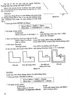
Add room labels and room ID numbers that are 300 mm tall as shown in the illustration:
■ 221 through 224 - SLEEPING QUARTERS
■ 201 - READY ROOM
■ 202 & 204 - LOCKER ROOM
■ 203 - EXERCISE ROOM
■ 205 - DINING ROOM
■ 206 - KITCHEN
■ 207 - MEN'S TOILET ROOM
■ 208 - WOMEN'S TOILET ROOM
5.
Save and close the drawing.
84 ■ Chapter 7: Annotating the Drawing
Imperial Units
1.
Open the drawing you saved from the previous challenge exercise, or open I_ARCH-Challenge-
CHP07.dwg.
2.
Make initial settings:
■ Return to Model Space.
■ Set the Annotation layer as current.
3.
Create a new text style with the following characteristics:
■ Style Name: Labels
■ Font Name: Arial
■ Height: 0
■ Width Factor: 0.9000
4.
Add room labels and room ID numbers that are 1' tall as shown in the illustration:
■ 221 through 224 - SLEEPING QUARTERS
■ 201 - READY ROOM
■ 202 & 204 - LOCKER ROOM
■ 203 - EXERCISE ROOM
■ 205 - DINING ROOM
■ 206 - KITCHEN
■ 207 - MEN'S TOILET ROOM
■ 208 - WOMEN'S TOILET ROOM
Challenge Exercise: Architectural ■ 85
5.
Save and close the drawing.
86 ■ Chapter 7: Annotating the Drawing
Challenge Exercise: Mechanical
In this exercise, you use what you learned about annotation to add annotation to the drawing views.
Note: The following illustration depicts only some of the views that require annotation.
The completed exercise
Completing the Exercise
To complete the exercise, follow the steps in this book or in the onscreen exercise. In
the onscreen list of chapters and exercises, click Chapter 7: Annotating the Drawing.
Click Challenge Exercise: Mechanical.
1.
Open the drawing you saved from the previous challenge exercise, or open M_MECH-Challenge-
CHP07.dwg.
2.
Make initial settings:
■ Make the Annotation layer current.
■ Thaw the Section Line layer.
3.
Create a new text style with the following characteristics:
■ Style Name: Labels
■ Font Name: Arial
■ Height: 0
■ Width Factor: 0.9000
Challenge Exercise: Mechanical ■ 87
4.
Annotate the drawing views by adding view labels that are 8.0 mm tall as shown in the following
illustrations. Note that the annotation indicated on the left side of the view reads Outfeed Side and
needs to be 4.0 mm in height.
88 ■ Chapter 7: Annotating the Drawing
5.
More views
6.
Save and close all files.
Chapter Summary ■ 89
Chapter Summary
Using the annotation commands, you can create and edit the annotation that is typically required in
drawings. By using the annotative properties of your annotations, you can create annotations that get
reused in many viewports at any desired scale.
Having completed this chapter, you can:
■ Use the Mtext command to create multiline text.
■ Create single line text.
■ Use different methods to edit text.
■ Create text styles to manage text.
90 ■ Chapter 7: Annotating the Drawing
Chapter Overview ■ 91
Chapter
8
Dimensioning
You use dimensions on drawings to convey size and specifications. Most drawings are not complete
until you have added dimensions.
When dimensioning a drawing, you need to consider the final output scale of the drawing, the
placement of dimensions, and how the dimensions should appear.
In this chapter, you learn how to create, edit, and manage dimensions in a typical design environment.
Objectives
After completing this chapter, you will be able to:
■ Create dimensions.
■ Use dimension styles to manage dimensions.
■ Create and edit multileader styles and multileaders.
■ Use different commands and methods to edit dimensions.
Standard Object Snap and Status Bar Settings
Before completing the exercises in this chapter, refer to the "Settings for the
Exercises" section in the Introduction in Volume 1.