Learning AutoCAD 2010, Volume 2 phần 5 pdf
Bạn đang xem bản rút gọn của tài liệu. Xem và tải ngay bản đầy đủ của tài liệu tại đây (9.29 MB, 37 trang )
Lesson: Using Dimension Styles ■ 141
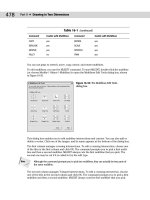
New Dimension Style Dialog Box - Primary Units Tab
Use the Primary Units tab to set options for the primary units displayed on the dimensions. You can set
the unit format for linear and angular dimensions, adjust the precision settings, use zero suppression
for the beginning and end of dimensions, and adjust the measurement scale factor for dimensioning
geometry that was not drawn at full scale. The primary units are always displayed and they reflect the
current drawing units setting.
142 ■ Chapter 8: Dimensioning
New Dimension Style Dialog Box - Alternate Units Tab
Alternate units are used when you need to show two measurement units, metric and imperial.
Use the Alternate Units tab to display and format alternate units on your dimensions. Select the
Display Alternate Units option to turn on alternate units. The remaining options are only available
after you select this option. You can adjust the unit format, precision, zero suppression, and
placement. The multiplier for alternate units is preset to convert from millimeters to inches in a metric
unit drawing or inches to millimeters in an imperial unit drawing.
By default, the Display alternate units option is turned off in the Standard and ISO-25 dimension
styles.
Lesson: Using Dimension Styles ■ 143
New Dimension Style Dialog Box - Tolerances Tab
Use the Tolerances tab to add tolerances to your dimensions. By adding tolerances to your dimensions,
you are setting a valid range in which the as-built measurement of the feature must be maintained in
order to ensure functionality.
You can select a method, set the tolerance precision, choose upper and lower values, scale the
tolerance text height, set the vertical position, and control zero suppression. If you are including
alternate units in your dimensions, set the alternate unit tolerance precision value and zero
suppression options here.
Procedure: Creating and Modifying Dimension Styles
The following steps give an overview of creating and modifying dimension styles.
1.
Start the Dimension Style command.
2.
In the Dimension Style Manager, click New or Modify.
3.
For a new dimension style, enter a name and click Continue. If you are modifying an existing dimension
style, proceed to the next step.
4.
Select the appropriate tabs in the Modify Dimension Style dialog box, depending on the features you
need to adjust. Select dimension style options as required. Click OK.
5.
In the Dimension Style Manager, click Close.
144 ■ Chapter 8: Dimensioning
Key Points
■ Dimension styles control the appearance of dimension features.
■ Dimension style options are based on general drafting standards.
■ Only one dimension style can be current at a time.
■ If you modify a dimension style, all dimensions using that style in the drawing update
automatically.
■ To set a dimension style current or to rename or delete a dimension style, select the name in the
Dimension Style Manager and right-click to access these options.
■ You cannot delete a dimension style if it is current or if it is being referenced in the drawing.
■ The quickest way to make a new dimension style current is to select it from the list in the
Dimensions panel.
■ A blank drawing based on the ACAD drawing template will contain a Standard style and an
Annotative style.
■ The Annotative dimension style will display dimensions that are equal in size regardless of the
viewport scale in the drawing Layout.
■ For non-annotative dimensions, you must set the dimension scale equal to your plot scale.
Lesson: Using Dimension Styles ■ 145
Exercise: Modify a Dimension Style
In this exercise, you modify the existing dimension style to allow the dimensions to appear correctly on the
sheet. You also change the dimension style to display architectural ticks instead of arrows, and alternate units.
The completed exercise
Completing the Exercise
To complete the exercise, follow the
steps in this book or in the onscreen
exercise. In the onscreen list of
chapters and exercises, click Chapter 8:
Dimensioning. Click Exercise: Modify a
Dimension Style.
1.
Open M_Dimension-Styles.dwg.
Note: The red lines around the floor plan
indicate objects that are actually dimensions,
but the annotative scale is not currently set
for the dimension text or other features to be
visible.
2.
Click the Paper button on the status bar to
change the display to Model space.
146 ■ Chapter 8: Dimensioning
3.
To modify the current dimension style's
arrowhead:
■ Select the Annotate tab on the ribbon. On
the Dimensions panel, click Dimension
Style. The current dimension style is
ISO-25.
■ In the Dimension Style Manager, click
Modify.
■ In the Modify Dimension Style dialog
box, Symbols and Arrows tab, under
Arrowheads, select Architectural Tick from
the First list.
Note: the Second arrowhead will automatically
default to the same selection.
4.
To modify the current dimension style's text
style setting:
■ Click the Text tab.
■ In the Text style list, select TECH.
Note: The text height for the dimensions is set
to 2.5.
5.
To modify the dimension style to be
annotative:
■ Click the Fit tab.
■ Under Scale for Dimension Features, click
Annotative.
■ Click OK.
6.
In the Dimension Style Manager, click Close.
Note that no changes in the drawing are
visible.
7.
To set the model space annotation scale:
■ On the status bar, Annotation Scale list,
click 1:50.
8.
To update the dimensions with the new
annotation scale:
■ On the Dimensions panel, click Dimension
Update.
■ Enter ALL.
■ Press ENTER to complete the selection.
■ Press ENTER.
Notice the effect that changing the annotation
scale has on the dimensions in the drawing.
9.
To change the dimension style to display
alternate units:
■ On the Dimensions panel, click Dimension
Style.
■ In the Dimension Style Manager, click
Modify.
■ In the Modify Dimension Style dialog box,
Alternate Units tab, click Display Alternate
Units.
■ In the Unit Format list, select Architectural
Stacked.
Lesson: Using Dimension Styles ■ 147
10.
Under Placement, select Below Primary Value.
Click OK.
11.
In the Dimension Style Manager, click Close to
exit the dialog box.
12.
To update the layout annotative scale:
■ Click the layout tab to return to the
drawing layout.
■ Click to select the viewport border.
■ On the status bar, Annotation Scale list,
click 1:50.
Note: You may need to click another scale then
click 1:50 to get the viewport scale to reset.
■ On the status bar, VP Scale, click to lock the
viewport.
The dimensions now appear at the correct
size in relation to the size of the sheet and the
viewport.
Note: The dimension update may take several
seconds to appear.
13.
Zoom to the drawing extents.
14.
Close all files without saving.
148 ■ Chapter 8: Dimensioning
Lesson: Using Multileaders
This lesson describes multileaders, multileader styles, and the options available for placing
multileaders in the drawing.
You use multileader objects for leader-based annotation. Leaders are important because they
enable you to connect features on the geometry to notes, balloon callouts, or other objects. Using
multileaders as leader objects provides greater flexibility and control than standard leader objects.
The following illustration shows multileader objects used for balloon callouts.
Objectives
After completing this lesson, you will be able to:
■ Describe multileaders.
■ Describe multileader styles.
■ Create and edit multileaders.
Lesson: Using Multileaders ■ 149
About Multileaders
Using multileaders, you can create associative leader-based annotation objects that behave
intelligently as a single object. Similar to associative dimensions, multileaders are treated as single
objects with specific object properties.
In the addition to this associativity, multileaders have additional options for placing, editing, and
managing leader-based annotation objects.
Definition of a Multileader
A leader is an annotation that includes an arrow, a leader line, a landing, and some form of text
or other object. A multileader is a style-based associative leader object that combines several
different common elements such as lines and text into a single associative object. When you select a
multileader object, grips are displayed at several points on the object. You can edit any of these points;
you select the grip and move it to a different location.
If you double-click a multileader, the Properties palette is displayed showing properties specific to the
multileader object. The initial property settings originate from the current multileader style, but can be
overridden just like properties on other objects.
150 ■ Chapter 8: Dimensioning
Selected multileader object
Multileader grips
Multileader object type identified in the Properties palette
Properties specific to multileader objects
Properties specific to multileader objects
Lesson: Using Multileaders ■ 151
Example of Multileaders
In the following illustration, two multileader objects are used to identify six different areas on the
drawing. Because the objects are style based and associative, if you need to make changes, you can do
so easily.
If standard leader objects were used in the drawing above, a change, such as print scale, would require
that you redraw all of the leaders and change the text height for each text note.
About Multileader Styles
Multileader objects are style-based, which means that the properties for the individual elements
originate from the current multileader style.
152 ■ Chapter 8: Dimensioning
In the following illustration, a typical multileader object is shown. While there are several properties
associated with a multileader, they can be organized into three main categories.
The Leader Format properties enable you to specify arrowhead type and size, as well as the leader
type, straight or spline.
The Leader Structure properties enable you to specify constraints on the leader line such as segment
angles, landing settings, and the overall leader scale or annotative property.
The Content properties enable you to specify the type of content that will be attached to the leader.
Command Access
Multileader Style
Command Line: MLEADERSTYLE
Ribbon: Annotate tab > Leaders panel > Multileader Style Manager
Menu Bar: Format > Multileader Style
Multileader Style Manager
You use the Multileader Style Manager to manage and edit multileader styles. The dialog box and
options work almost identically to the Dimension Style Manager. You use this dialog box to create,
edit, delete, and set current multileader styles.
Lesson: Using Multileaders ■ 153
Modify Multileader Style
You use the Modify Multileader Style dialog box to edit the properties associated with the multileader
style. Style properties are organized on three tabs with each tab containing specific types of
properties. As soon as you exit the Multileader Style Manager, changes you made to an existing style
are reflected automatically on any multileaders that are using the style.
154 ■ Chapter 8: Dimensioning
Multileader Content Types
You can specify three different content types for multileader objects. On the Content tab of the Modify
Multileader Style dialog box, you can select from the following:
Block
Mtext
None
Several default blocks are
available such as circle,
slot, and triangle. The
default block options
contain attributes. You
can also specify your own
block. You are prompted
for values when you create
the multileader.
This is the default
multileader type and
consists of mtext objects.
This multileader object contains a leader only.
Using Multileaders
Using multileaders involves several tasks. These include creating and managing multileader styles,
placing multileaders, adding leaders, and aligning and collecting multileaders.
With the exception of creating and managing multileader styles, which should generally be done first,
there is no prescribed order for creating and editing multileaders or for using any of the multileader
tools.
Lesson: Using Multileaders ■ 155
Multileaders Ribbon Panel
You use the Multileaders panel to access tools specific to creating and editing multileaders. The
panel contains the standard buttons for accessing commands as well as a multileader style list that
you use to set the active multileader style. You can also use the list to change the style of a selected
multileader object.
The following commands are found on the Leader panel in the Annotate tab.
Icon
Command
Description
Multileader
Creates a single multileader object.
Add Leader
Adds leader lines to existing multileader objects.
Remove
Leader
Removes leader lines from existing multileader objects.
Align
Multileaders
Aligns multileaders horizontally or vertically in the drawing.
Collect
Multileaders
Collects multiple multileaders and combines them into a single multileader
object with multiple content elements.
156 ■ Chapter 8: Dimensioning
Process: Using Multileaders
The following steps describe the overall process for using multileaders.
1.
Determine the multileader
style you want to use:
Depending on your needs,
you may need to create a
new style or edit an existing
one. The product provides
two default styles. You can
use them as is, modify them,
or create new ones.
2.
Use the Mleader command
to create multileaders.
3.
Use the Add Leader or
Remove Leader tools to
modify existing multileaders.
4.
Use the Align Multileaders
and Collect Multileader
tools to further modify the
appearance of multileaders
on the drawing.
Lesson: Using Multileaders ■ 157
Guidelines
■ Use Annotative scaling or the Annotativestylefor your multileader. This makes the multileaders in
drawings that have multiple views the same size.
■ You do not need a style for small or individual changes to a multileader. You can use the Properties
palette to change individual properties for selected multileader objects.
■ After you have placed a multileader, you can adjust its location using grips.
Using Dimension Break
You can use the Dimbreak command to break multileader objects at intersections of
objects or dimensions in the drawing.
158 ■ Chapter 8: Dimensioning
Exercise: Use Multileaders
In this exercise, you create a multileader style to add callouts to an exploded view drawing. You then add
multileaders to the drawing using different options associated with multileaders.
The completed exercise
Completing the Exercise
To complete the exercise, follow the
steps in this book or in the onscreen
exercise. In the onscreen list of
chapters and exercises, click Chapter
8: Dimensioning. Click Exercise: Use
Multileaders.
1.
Open c_Front-Pump-Assembly.dwg.
2.
To create a new multileader style:
■ On the Leaders panel, click the Multileader
Style Manager dialog box launcher.
■ In the Multileader Style Manager dialog
box, click New.
■ In the Create New Multileader Style
dialog box, New Style Name, enter
Balloon_Callout. Click Continue.
Lesson: Using Multileaders ■ 159
3.
To assign the Content type:
■ Click the Content tab.
■ In Multileader Type, select Block from the
list.
■ Under Block Options, select Circle from the
list. Click OK.
4.
In the Multileader Style Manager, verify that
Balloon_Callout is the current multileader
style. Click Close.
5.
Check the Object Snap Settings to ensure that
Endpoint, Midpoint, and Intersection snap
modes are selected.
6.
To place a Multileader:
■ On the Leaders panel, click Multileader.
■ Using Object Snap, select the Midpoint of
the top line of the keyway (1).
■ Move the cursor above the pulley and click
a location (2).
■ Notice the command line. An attribute has
been assigned to this block.
Enter 1 (3).
160 ■ Chapter 8: Dimensioning
7.
Using the same steps, place a multileader for
the pulley and seal as shown. Enter 2 for the
pulley and 3 for the seal.
8.
To align multileaders:
■ On the Leaders panel, click Align.
■ Use a crossing window to select all three
multileaders. Press ENTER.
■ Right-click to access the shortcut menu.
Click Options. Click Distribute.
■ Select a point on the highest multileader
(1).
■ Move the cursor horizontally with Polar
Tracking, indicating that the motion is
straight (2). Try not to select an object snap
because this may override the horizontal
direction.
■ Click to align the multileaders.
Lesson: Using Multileaders ■ 161
9.
Place a multileader on the bearing as shown.
Enter 5.
10.
To add a multileader to an existing multileader:
■ On the Leaders panel, click Add Leader.
■ Select the number 5 multileader.
■ For the second leader arrowhead location,
select the bearing at the other end of the
shaft. Press ENTER.
11.
Add multileaders 4, 8, and 9 to the front pump
housing.
12.
To collect multileaders:
■ On the Leaders panel, click Collect.
■ Individually select multileaders 4, 8, and 9
in order. Press ENTER.
■ Verify in the Command line that Horizontal
is the current option. If not, right-click and
select it from the shortcut menu.
■ Click to place the collected multileaders.
162 ■ Chapter 8: Dimensioning
13.
To add a multileader specifying content first:
■ On the ribbon, Leaders panel, click
Multileader.
■ Right-click. Click Options.
■ Select Content type.
■ Click a location below the number 5
callout. Enter 6.
■ Locate the arrowhead of the multileader to
the shaft.
14.
To add a multileader specifying the landing
first:
■ On the Leaders panel, click Multileader.
Enter L. Press ENTER.
Note: You can right-click in the Command line
or enter the capitalized letter of the command
options.
■ Click a point to the left of the rear housing
to locate the callout.
■ Click the rear housing to locate the
arrowhead. Enter 7.
15.
Using the options of your choice, add a
multileader to the last part in the exploded
view. Enter 3.
16.
Close all files without saving.
Lesson: Editing Dimensions ■ 163
Lesson: Editing Dimensions
This lesson describes how to edit dimensions, but mainly how to edit dimension text. There are
a variety of ways to edit dimensions depending on what kind of editing you need to do. You can
reposition dimensions using grips. You can edit dimension features that override the dimension style,
you change dimensions from one style to another, and you can edit the dimension text.
Inevitably, once you place dimensions in the drawing, you will need to edit them either by
repositioning or adding additional information to the dimension.
In the following illustration, a string of continuous dimensions is being moved to a new position using
grips.
Objectives
After completing this lesson, you will be able to:
■ Edit dimensions using grips and the Dimedit and Dimtedit commands.
164 ■ Chapter 8: Dimensioning
Editing Dimensions
You can use the Dimedit command to edit or override the dimension text measurement. You can
use the Dimtedit command to edit the position of the dimension text. You can also right-click a
selected dimension to access the Quick Properties or the Properties palette where you can edit any
of the dimension style features for the selected dimension. Any global changes that you make to the
dimension style do not affect the changes that you have made to the individual dimensions unless you
change the selected dimension from one dimension style to another.
In addition to editing the dimension style features from the Properties palette, you can also edit
dimension text.
Note: The arrows (<>) keep the original text measurement that is associated to the object
dimensioned.
Command Access
Dimension Edit - Edit Text
Command Line: DDEDIT
Pointing Device: Double-click a text object.
Dimension Edit - Justify Text
Command Line: DIMTEDIT
Lesson: Editing Dimensions ■ 165
Dimension Edit - Justify Text
Ribbon: Annotate tab > extended Dimensions panel > Text Angle (1), Left Justify (2), Center Justify
(3), Right Justify (4)
Dimension Edit - Oblique Angle
Command Line: DIMEDIT
Home, New, and Rotate are also DIMEDIT options when entered at the command line.Note: Home,
New, and Rotate are also DIMEDIT options when entered at the command line.
Ribbon: Annotate tab > extended Dimensions panel > Oblique
The quickest way to edit the dimension text measurement is with the DDEDIT
command. When you type over the text it will override the associative feature of
the dimension text measurement. If you type <> before of after the associative
dimension text, the associative measurement continues to be displayed.
Procedure: Adding Text to a Dimension with DDEDIT
The following steps give an overview of how to add text to a dimension using the Dimedit command.
1.
On the command line, enter ddedit to start the DDEDIT command.
2.
Select the dimension text to Edit.