Learning AutoCAD 2010, Volume 2 phần 9 doc
Bạn đang xem bản rút gọn của tài liệu. Xem và tải ngay bản đầy đủ của tài liệu tại đây (9.29 MB, 37 trang )
Lesson: Creating Ellipses ■ 289
5.
Move the cursor straight up and click at the
intersection.
6.
Click at the center of the first ellipse.
7.
To trim part of the second ellipse:
■ Start the Trim command.
■ Click the first ellipse as the cutting edge.
■ Click the far left side of the second ellipse
as the object to trim.
The left ellipse is trimmed to an elliptical arc,
as shown.
8.
To create an ellipse in the top view to
represent the outer edge of the inclined
surface:
■ On the Home tab, click Draw panel >
Ellipse.
■ Right-click. Click Arc.
■ Right-click. Click Center.
9.
Click the center of the first ellipse.
10.
To define the endpoint of the first axis, snap to
the end of the horizontal line.
11.
To define the endpoint of the second axis, snap
to the intersection on the right.
12.
To specify the start angle, snap to the end of
the horizontal line.
13.
To specify the end angle position, snap to the
end of the horizontal line on the top.
14.
Freeze layer construction. Zoom to display
your completed drawing.
15.
Close all files. Do not save.
290 ■ Chapter 11: Creating Additional Drawing Objects
Lesson: Using Tables
This lesson describes how to create and modify table styles, and how to create tables using the
Tablestyle and Table commands.
You can use tables in your drawings to meet a number of needs. For example, you might use them to
show revisions in the drawing, or to create tabulated dimensions, as shown.
The following illustration represents a tabular dimension table.
Objectives
After completing this lesson, you will be able to:
■ Describe tables.
■ Use the Tablestyle command to create table styles.
■ Create tables and enter values in the table cells.
Lesson: Using Tables ■ 291
About Tables
You can use tables to organize data into columns and rows. Data can be entered in the table or
extracted from objects including blocks that contain special attributes. When you place information
into tables, you can format rows and columns and apply formulas.
Definition of a Table
Tables contain rows and columns which create an array of individual cells that are designated by the
row number and column letter in which the cell resides.
A table is a database that exists within the AutoCAD program.
292 ■ Chapter 11: Creating Additional Drawing Objects
Example of Using Tables
You use the Table command to insert a table into your drawing. You specify the number of rows and
columns, the heading style, and other parameters. You can create a variety of table styles to use
within your drawing. The Table and Table Style commands insert and create a database that is unique
to this program.
This is not the same as inserting an external database from another program using OLE Objects
(Object Linking and Embedding), which is not covered in this course.
Lesson: Using Tables ■ 293
Creating Table Styles
Table styles are similar to the concept of dimension styles because they set the format for tables in the
drawing. You create and manage them with the Tablestyle command.
You can have more than one table style, but each new drawing you create contains only one table style
called Standard. If you create additional table styles, use the Table Styles list on the Styles toolbar to
set the current table style.
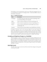
Like dimension styles, if you make a change to a table style, any table using that style in the drawing
updates to reflect the changes.
The following illustration demonstrates the effect of modifying a table style.
294 ■ Chapter 11: Creating Additional Drawing Objects
Command Access
Table Styles
Command Line: TABLESTYLE
Ribbon: Home tab > Annotation extended panel > Table Style
Ribbon: Annotate tab > Tables panel > Table Style
Lesson: Using Tables ■ 295
Table Style Dialog Box
You use the Table Style dialog box to create, modify, and manage table styles.
Select the table style to set it as current, to base a new style on, or to modify.
Click to make the selected style current.
Click to create a new style based on the selected style.
Click to edit the selected style.
296 ■ Chapter 11: Creating Additional Drawing Objects
New Table Style Dialog Box
Use the New Table Style dialog box to set the properties for a new table style.
Use the default table style or one of your own as the basis for the new style.
Select the table direction: up or down.
Refer to the preview as you make modifications to the style.
Create and save your styles for the Data, Header, and Title cells.
Set the properties for Data, Header, and Title cell styles.
Set your margins for the chosen cell style. Different margins can be set for the Data, Header, and Title
cells.
Lesson: Using Tables ■ 297
Procedure: Creating Table Styles
The following steps give an overview of creating table styles.
1.
Start the Tablestyle command.
2.
In the Table Style dialog box, click New.
3.
Enter a name for the new table style. Select an existing style in the Start With list. Click Continue.
4.
In the New Table Style dialog box, adjust the general, text, and borders properties in the Cell styles area
for the Data, Header, and Title cells. Click OK.
5.
In the Table Style dialog box, double-click the new table style to make it the current style.
Table Style Key Points
■ Table styles control the appearance of tables.
■ You can have more than one table style, but only one table style can be current.
■ Each new drawing contains a table style called Standard.
■ If you make a change to a table style, existing tables using that style update to reflect the changes.
Creating Tables and Entering Table Data
There are three main steps to inserting a table. First, select the table style; second, place the table
in the drawing; and third, enter data in the appropriate cells. When you select the style in the Insert
Table dialog box, you can also set the number and size of the columns and data rows.
You double-click a cell to enter data using the In-Place Text Editor, similar to the way you edit multiline
text. To navigate the cells, use standard keyboard navigation techniques such as the TAB or ARROW
keys.
Single-click a cell to access the table formatting options.
298 ■ Chapter 11: Creating Additional Drawing Objects
Command Access
Table
Command Line: TABLE
Ribbon: Home tab > Annotation panel > Table
Ribbon: Annotate tab > Tables panel > Table
Insert Table Dialog Box
To insert a table, you first select the table style to use for the new table and then select whether the
table should be inserted at a specific point or by using a window. Under Column & Row Settings, you
adjust the options for the number of columns, column width, number of data rows, and row height.
Lesson: Using Tables ■ 299
Select your desired table style or click to create a new style.
Select your insert option.
■ Start from an empty table.
■ From a data link. Use this option to select an existing spreadsheet to link to as a table.
■ From object data in the drawing. Use this option to extract data from an existing object in your
drawing.
Choose to insert your table by a corner point or by selecting a windowed area to fit into.
Choose the number of columns and rows, the column width, and the row spacing.
Select a cell style for the first row cell, the second row cell, and all remaining cells.
Observe your preview window to verify your settings.
Using the Specify Window option, you can dynamically adjust the number of cells
in the table based on the size of the table window you specify. When you select this
option, the options for the number of columns and the row height are set to Auto
and you can specify the column width and number of rows.
300 ■ Chapter 11: Creating Additional Drawing Objects
Warning!
In the Insert Options area, the From Object Data In The Drawing (Data Extraction)
option is not available in AutoCAD LT®.
Procedure: Inserting a Table
The following steps give an overview of inserting a table.
1.
Start the Table command.
2.
In the Insert Table dialog box, select the table style. Set the Insert Behavior and Column and Row
Settings options. Click OK.
3.
Specify an insertion point for the table. If you used the Specify Window option, click two points to
define the table size.
The first cell in the table is automatically activated for editing.
Procedure: Navigating and Entering Table Data
The following steps give an overview of navigating and entering data in a table.
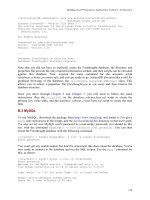
1.
Double-click a cell in the table to start the In-Place Text Editor. Enter the required values in the cell.
2.
To navigate to other cells, you can use the TAB key to move to the right, SHIFT+TAB to move to the left,
or the ARROW keys to navigate in any direction.
3.
You can enter standard spreadsheet-style formulas in the cells to reference other cells in the table.
Lesson: Using Tables ■ 301
4.
You can copy a formula or value from one cell to multiple cells using the Auto-Fill grip. Click the cell to
be copied and then click the cell's Auto-Fill grip (1). Drag your mouse up or down over the cells to copy
and click in the last cell to complete the copy (2).
5.
To finish editing the table, press ESC.
Table Data Guidelines
■ You can enter formulas in table cells.
■ Cell formulas can range from simple math formulas to formulas referencing other cells, even cells
in other tables in the drawing.
■ Use fields to extract data from objects in your drawing. For example, you can place the area of a
closed polygon into a cell.
■ Use the Auto-Fill grip to copy a formula or value from one cell to multiple cells.
■ Use standard Windows Cut, Copy, and Paste commands to efficiently populate your cells.
302 ■ Chapter 11: Creating Additional Drawing Objects
Exercise: Create a Dimension Table
In this exercise, you create a new table style using the Tablestyle command. You create a new table containing
tabulated dimensions for the design. You enter static values in the table as well as a formula that you copy to
other cells.
The completed exercise
Completing the Exercise
To complete the exercise, follow the
steps in this book or in the onscreen
exercise. In the onscreen list of
chapters and exercises, click Chapter
11: Creating Additional Drawing
Objects. Click Exercise: Create a
Dimension Table.
1.
Open M_Create-Table.dwg.
2.
To create a new table style and make it
current:
■ On the Annotation panel (or Annotate tab
> Tables panel), click Table Style.
■ In the Table Style dialog box, click New.
■ In the Create New Table Style dialog box,
enter NT-2.5.
■ Click Continue.
3.
To specify text height for data cells:
■ Click the Data Cell style.
■ Click the Text tab.
■ For Text Height, enter 2.5.
Lesson: Using Tables ■ 303
4.
To specify the text height for column cells:
■ Click the Header cell style.
■ Click the Text tab.
■ For Text Height, enter 3.5.
■ Click OK.
5.
To make the new table style current:
■ In the Table Style dialog box, double-click
the new style.
■ Click Close.
6.
To place a table in the drawing:
■ Start the Table command.
■ In the Insert Table dialog box, under
Insertion Behavior, click Specify Insertion
Point.
■ Under Column & Row Settings, adjust the
options as shown.
■ Under Set Cell Styles, adjust the options as
shown to create a table with no title row.
■ Click OK.
7.
Specify an insertion point for the table as
shown.
304 ■ Chapter 11: Creating Additional Drawing Objects
8.
The In-Place Text Editor appears with the first
cell in the table ready for editing:
■ Enter PART NAME and press TAB.
Tip: Press ALT+ENTER to create a second line in
the cell.
■ Enter A and press TAB.
■ Enter B and press TAB.
■ Enter C and press TAB. Your table should
appear as shown.
Note: If you need to move the table, select the
table, and then move it by selecting the top
corner grip.
9.
Zoom in to the table.
10.
To add additional data to the table cells:
■ Double-click the empty cell under PART
NAME.
■ Enter B762, and then press DOWN ARROW.
■ Continue entering values in the cells as
shown, pressing DOWN ARROW to move
to the cell below.
11.
Continue entering values in the table:
■ After entering the data in the last row,
press TAB to move to the next column.
■ Press UP ARROW to move to the top of the
table.
■ Enter the values as shown for Column A.
Tip: The numbers are the same as the PART
NAME column without the B prefix.
12.
Enter a formula in a cell:
■ Press TAB to move to the last row in the
next column.
■ Enter =B6-76. This subtracts 76 from the
value of cell B:6.
Note: Do not confuse the labels in the table
with the actual cell letter or number. Functions
must reference the actual cell location.
■ Click OK to close the In-Place Text Editor.
Lesson: Using Tables ■ 305
13.
To copy the contents of one cell to others:
■ Click the cell containing the formula to
highlight it.
■ Click the Auto-Fill grip (1).
■ Move your cursor upward (2).
■ Click anywhere in the top cell (3).
The copied formula is pasted into the other
cells, maintaining reference to relative cell
numbers.
■ Press ESC to clear the selection.
14.
To add the remaining data to column C:
■ Double-click the first cell in the last
column.
■ Enter the values as shown.
15.
Compare the values in your table to the values
shown.
16.
Zoom to the drawing extents.
17.
Close all files without saving.
306 ■ Chapter 11: Creating Additional Drawing Objects
Challenge Exercise: Architectural
In this exercise, you use what you learned about creating drawing objects to create a table, a closed
polyline for calculating an area, and spline topographic lines.
You have the option of completing this exercise using either imperial or metric units.
Select one version of the exercise to complete the steps.
The completed exercise
Completing the Exercise
To complete the exercise, follow the steps in this book or in the onscreen exercise.
In the onscreen list of chapters and exercises, click Chapter 11: Creating Additional
Drawing Objects. Click Challenge Exercise: Architectural Metric.
Challenge Exercise: Architectural ■ 307
Metric Units
1.
Open the drawing you saved from the previous challenge exercise, or open M_ARCH-Challenge-
CHP11.dwg.
2.
Set layers and create contours.
■ Thaw and set current the existing layer, Topo.
■ Draw smooth curved contours from node to node as shown.
3.
Calculate the square area of the lot this fire station sits on. The lot is shown with the blue grips active in
the following image.
308 ■ Chapter 11: Creating Additional Drawing Objects
4.
Place a title block on the layout.
■ Activate the Plan View layout.
■ Insert the block Titleblock centered on the layout.
■ Add text to the title block as shown.
5.
Add and configure two viewports.
■ A view of the elevation detail at a scale of 1:100.
■ The key plan in the upper-right corner of the title block, zoomed to fit.
For each of the viewport configurations, adjust the layer display to achieve the results shown.
Challenge Exercise: Architectural ■ 309
6.
Create a table showing the following Room Schedule data:
■ NUMBER - NAME - AREA
■ 221 - SLEEPING QUARTERS - 21 m2
■ 201 - READY ROOM - 36 m2
■ 202 - LOCKER ROOM - 14 m2
■ 203 - EXERCISE ROOM - 23 m2
■ 205 - DINING ROOM - 24 m2
■ 206 - KITCHEN - 6 m2
■ 207 - MEN'S TOILET ROOM - 11 m2
■ 208 - WOMEN'S TOILET ROOM - 14 m2
7.
Save and close the drawing.
Imperial Units
1.
Open the drawing you saved from the previous challenge exercise, or open I_ARCH-Challenge-
CHP11.dwg.
2.
Set layers and create contours.
■ Thaw and set current the existing layer, Topo.
■ Thaw the layer, Site - Concrete.
■ Draw smooth curved contours from node to node as shown.
3.
Calculate the square area of the lot this fire station sits on. The lot is shown with the blue grips active in
the following image.
310 ■ Chapter 11: Creating Additional Drawing Objects
4.
Place a title block on the layout.
■ Activate the Plan View layout.
■ Insert the block Titleblock centered on the layout.
■ Add text to the title block as shown.
5.
Add and configure two viewports.
■ A view of the elevation detail at a scale of 1/8" = 1'.
■ The key plan in the upper-right corner of the title block, zoomed to fit.
For each of the viewport configurations, adjust the layer display to achieve the results shown.
Challenge Exercise: Architectural ■ 311
6.
Create a table showing the following Room Schedule data:
■ NUMBER - NAME - AREA
■ 221 - SLEEPING QUARTERS - 236 SQ/FT
■ 201 - READY ROOM - 386 SQ/FT
■ 202 - LOCKER ROOM - 150 SQ/FT
■ 203 - EXERCISE ROOM - 383 SQ/FT
■ 205 - DINING ROOM - 134 SQ/FT
■ 206 - KITCHEN - 200 SQ/FT
■ 207 - MEN'S TOILET ROOM - 114 SQ/FT
■ 208 - WOMEN'S TOILET ROOM - 149 SQ/FT
7.
Save and close the drawing.
312 ■ Chapter 11: Creating Additional Drawing Objects
Challenge Exercise: Mechanical
In this exercise, you use what you learned about creating drawing objects to represent an edge on a
part, create a border around a view, and create a closed loop to calculate area. You will also update
your layout including a titleblock.
The completed exercise
Completing the Exercise
To complete the exercise, follow the steps in this book or in the onscreen exercise.
In the onscreen list of chapters and exercises, click Chapter 11: Creating Additional
Drawing Objects. Click Challenge Exercise: Mechanical.
1.
Open the drawing you saved from the previous challenge exercise, or open M_MECH-Challenge-
CHP11.dwg.
2.
In the side views for both the base part and assembly, the cut for the hole is too high with an arc. Draw
the representation correctly using an ellipse.
Challenge Exercise: Mechanical ■ 313
3.
Change the border around the detail view from a circle to a spline shape.
4.
Calculate the square millimeter area of the two flat surfaces in the front view of the base part.
(Value Check: The area of the lower face = 17185.9487)
5.
Update the Parts layout.
■ Switch to the Parts layout.
■ Insert the Titleblock block.
6.
Save and close the drawing.