MasteringAutoCAD 2011 and AutoCAD LT 2011 phần 9 docx
Bạn đang xem bản rút gọn của tài liệu. Xem và tải ngay bản đầy đủ của tài liệu tại đây (6.37 MB, 124 trang )
saving, loading, and unloading your Customizations
|
957
5. Repeat step 4 for each custom component you’ve created.
6. When you’ve copied everything from the left group to the right, click the drop-down list
in the Customizations In New File title bar, and select Save As.
7. In the Save As dialog box, enter a name for your customization file, and select a location.
8. Click Save to complete the process.
Your customization is saved with the .cuix filename extension. Once it’s saved as a file, you
can load it into another copy of AutoCAD by doing the following:
1. Open the Customize User Interface dialog box.
2. Click the Load Partial Customization File tool in the Customizations In All Files group
title bar.
3. In the Open dialog box, locate and select your CUI file, and then click Open.
4. Back in the Customize User Interface dialog box, click OK.
5. If your CUI file contains menus, enter Workspace↵↵↵ at the Command prompt. Or select
a workspace from the Workspace Switching tool in the status bar. If it contains toolbars,
right-click in a blank area next to an existing docked toolbar, and then select the name of
your CUI file and the toolbar.
As an alternative to using the Customize User Interface dialog box, you can use the CUIload
command. Enter Cuiload↵ at the Command prompt to open the Load/Unload Customizations
dialog box.
Click the Browse button to locate and select your CUI file. Once you’ve done this, the name
of your file appears in the File Name input box. You can then click the Load button to import it
into your AutoCAD session.
Finally, if you want to unload a CUI file, do the following:
1. Open the Customize User Interface dialog box.
2. Scroll down to the bottom of the list in the Customizations In All Files group, and expand
the Partial Customization Files item.
3. Right-click the partial CUI file you want to unload, and select Unload name.cuix.
4. Close the dialog box by clicking OK.
621974c28.indd 957 4/26/10 12:41:13 PM
958
|
CHAPTER 28 Customizing toolbars, menus, linetypes, and HatCH patterns
Understanding the Diesel Macro Language
Diesel is one of many macro languages AutoCAD supports, and you can use it to perform sim-
ple operations and add some automation to menus. As with AutoLISP, parentheses are used to
enclose program code.
In the following sections, you’ll look at the different ways to use the Diesel macro lan-
guage. You’ll start by using Diesel directly from the command line. This will show you how
a Diesel macro is formatted and will give you a chance to see Diesel in action. Then you’ll go
on to see how Diesel can be used as part of a menu option to test AutoCAD’s current state. In
the third section, you’ll see how Diesel can be used as part of the menu label to control what
is shown in the menu. Finally, you’ll learn how to use Diesel with field objects to control text
in your drawing.
Using Diesel at the Command Line
You can use Diesel at the AutoCAD command line by using a command called Modemacro. The
Modemacro command sends information to the status bar. Diesel can be used with Modemacro
to perform simple tasks.
Try the following exercise to experiment with Diesel:
1. At the Command prompt, type Modemacro↵.
2. At the Enter new value for MODEMACRO, or . for none <” “>: prompt, enter
$(/,25,2)↵. The answer to the equation appears at far left in the status bar.
The answer to the equation appears here.
3. To clear the status bar, enter Modemacro↵.↵.
The equation you entered in step 2 is referred to as an expression. The structure of Diesel
expressions is similar to that of AutoLISP expressions. The dollar sign tells AutoCAD that the
information that follows is a Diesel expression.
A Diesel expression must include an operator of some sort, followed by the items to be oper-
ated on. An operator is an instruction to take a specific action, such as adding two numbers or
dividing one number by another. Examples of mathematical operators include the plus sign (+)
for addition and the forward slash (/) for division.
The operator is often referred to as a function and the items to be operated on as the arguments
to the function, or simply the arguments. In the expression (/,25,2), the / is the function and 25
and 2 are the arguments. All Diesel expressions, no matter what size, follow this structure and
are enclosed by parentheses.
Parentheses are important elements of an expression. All parentheses must be balanced; for
each left parenthesis, there must be a right parenthesis.
621974c28.indd 958 4/26/10 12:41:14 PM
understanding tHe diesel maCro language
|
959
You can do other things with Diesel besides performing calculations. The Getvar function is
an AutoLISP function that you can use to obtain the drawing prefix and name. Try the following
to see how Diesel uses Getvar:
1. Type Modemacro↵ again.
2. Type $(getvar,dwgprefix)↵. The location of the current drawing appears in the status bar.
3. Press ↵ to reissue the Modemacro command; then type $(getvar,dwgname)↵. The name
of the drawing appears in the status bar.
In this example, the Getvar function extracts the drawing prefix and name and displays it in
the status bar. You can use Getvar to extract any system variable you want. If you’ve been work-
ing through the tutorials in this book, you’ve seen that virtually all AutoCAD settings are also
controlled through system variables. (The AutoCAD Help window contains a list of all the sys-
tem variables.) This can be a great tool when you’re creating custom menus because with Getvar,
you can poll AutoCAD to determine its state. For example, you can find out what command is
currently being used. Try the following exercise to see how this works:
1. Click the Line tool on the Draw panel.
2. Type ´Modemacro↵. The apostrophe at the beginning of Modemacro lets you use the
command while in another command.
3. Type $(getvar,cmdnames)↵. The word LINE appears in the status bar, indicating that the
current command is the Line command.
Diesel can be useful in a menu when you want an option to perform a specific task depending
on which command is currently active.
LT Users Can Use Diesel
LT users can’t use AutoLISP to find the location of AutoCAD resource files. However, you can use
the Diesel macro language. For example, to find the log file path, enter Modemacro and then
$(getvar,logfilepath). The path is displayed in the status bar. To get the status bar tools back, enter
Modemacro and then enter a period.
Using Diesel in a Custom Menu Macro
So far, you’ve been experimenting with Diesel through the Modemacro command. Using Diesel
in a menu macro requires a slightly different format. You still use the same Diesel format of a
dollar sign followed by the expression, but you don’t use the Modemacro command to access
Diesel. Instead, you use $M=. You can think of $M= as an abbreviation for Modemacro.
Here’s a Diesel expression that you can use in a menu macro:
^C^C_Blipmode;$M=$(-,1,$(getvar,Blipmode))
This menu option turns Blipmode on or off depending on Blipmode’s current state. As you
may recall, Blipmode is a feature that displays point selections in the drawing area as tiny crosses.
621974c28.indd 959 4/26/10 12:41:14 PM
960
|
CHAPTER 28 Customizing toolbars, menus, linetypes, and HatCH patterns
These tiny crosses, or blips, don’t print and can be cleared from the screen with a redraw. They can
be helpful when you need to track your point selections.
In this example, the Blipmode command is invoked, and then the $M= tells AutoCAD that a
Diesel expression follows. The expression
$(-,1,$(getvar,Blipmode))
returns either 1 or a 0, which is applied to the Blipmode command to turn it either on or off. This
expression shows that you can nest expressions. The most deeply nested expression is evaluated
first, so AutoCAD begins by evaluating
$(getvar,Blipmode)
This returns either 1 or a 0, depending on whether Blipmode is on or off. Next, AutoCAD
evaluates the next level in the expression
$(-,1,getvar_result)
in which getvar_result is either 1 or a 0. If getvar_result is 1, the expression looks like
$(-,1,1)
which returns 0. If getvar_result is 0, the expression looks like
$(-,1,0)
which returns 1. In either case, the end result is that the Blipmode command is assigned a value
that is opposite of the current Blipmode setting.
Using Diesel as a Menu Bar Option Label
In the previous example, you saw how to use Diesel in a menu macro to read the status of a
command and then return a numeric value to alter that status. You can also use Diesel as part of
the menu bar option name so the text it displays depends on certain conditions. The following
expression shows how to write a menu option name to display the current setting for Blipmode.
It includes Diesel code as the menu option label:
$(eval,Blipmode = $(getvar,blipmode))
Normally, you would just have a menu name, but here you see some Diesel instructions.
These instructions tell AutoCAD to display the message Blipmode = 1 or Blipmode = 0 in the
menu, depending on the current Blipmode setting. You would place this code in the Properties
group for the Blipmode custom command in the Customize User Interface dialog box. It goes in
the Display/Name input box.
621974c28.indd 960 4/26/10 12:41:14 PM
understanding tHe diesel maCro language
|
961
Here’s how it works. You see the familiar $(getvar,blipmode) expression, this time embed-
ded in a different expression. You know that $(getvar,blipmode) returns either 1 or a 0,
depending on whether Blipmode is on or off. The outer expression
$(eval,Blipmode = getvar_result)
displays Blipmode = and then combines this with getvar_result, which, as you’ve learned,
will be either 1 or 0. The eval function evaluates any text that follows it and returns its contents.
The end result is the appearance of Blipmode = 1 or Blipmode = 0 in the menu, depending on
the status of Blipmode. Here’s how the properties looks as a menu bar option under the Tools list
of the Menus option in the Customizations In All Files panel.
You can get even fancier and set up the menu option label to read Blipmode On or Blipmode
Off by using the if Diesel function. Here’s that same menu listing with additional Diesel code
to accomplish this:
$(eval,Blipmode = $(if,$(getvar,blipmode),Off,On))
In this example, the simple $(getvar,blipmode) expression is expanded to include the if
function. The if function reads the result of $(getvar,blipmode) and then returns the Off or
On value depending on whether $(getvar,blipmode) returns 0 or a 1. Here’s a simpler look at
the expression:
$(if, getvar_result, Off, On)
If getvar_result returns 1, the if function returns the first of the two options listed after
getvar_result, which is Off. If getvar_result returns 0, the if function returns On. The second
of the two options is optional. Here’s how the fancier Blipmode option appears in a menu.
You’ve just skimmed the surface of what Diesel can do. To get a more detailed description of
how Diesel works, press the F1 function key to open the AutoCAD 2011 Help website. Click the
Contents tab, expand the Customization Guide listing, and click the DIESEL listing that appears.
Table 28.2 shows some of the commonly used Diesel functions. Check the AutoCAD Help
dialog box for a more detailed list.
Table 28.2: Sample of Diesel functions
Code Function Example result Comments
+ Add $(+,202,144)
346
– Subtract $(-,202,144)
58
621974c28.indd 961 4/26/10 12:41:15 PM
962
|
CHAPTER 28 Customizing toolbars, menus, linetypes, and HatCH patterns
Code Function Example result Comments
* Multiply $(*,202,144)
29,088
/ Divide $(/,202,144)
1.4028
= Equal to $(=,202,144)
0 If numbers are equal,
1 is returned.
< Less than $(<,202,144)
0 If the first number is
less than the second,
1 is returned.
> Greater than $(>,202,144)
1 If the first number is
greater than the second,
1 is returned; otherwise
0 is returned.
! Not equal to $(!,202,144)
1 If the numbers are equal,
0 is returned.
<= Less than or
equal to
$(<=,202,144)
0 If the first number is less
than or equal to the sec-
ond, 1 is returned.
>= Greater than or
equal to
$(>=,202,144)
1 If the first number is
greater than or equal to
the second, 1 is returned;
otherwise 0 is returned.
eq Equal string $(eq,Yes, No)
0 If both text strings are the
same, 1 is returned.
eval Evaluate text $(eval,Here I Am)
Here I Am Returns the text
that follows.
getvar Get system
variable value
$(getvar,ltscale)
Current
linetype
scale
Returns the value of the
system variable.
if If/Then $(if,1,Yes,No)
Yes The second argument
is returned if the first
argument evaluates to 1.
Otherwise, the third argu-
ment is returned. The third
argument is optional.
Note: To indicate true or false, Diesel uses 1 or 0.
Table 28.2: Sample of Diesel functions (continued)
621974c28.indd 962 4/26/10 12:41:15 PM
understanding tHe diesel maCro language
|
963
Using Diesel and Fields to Generate Text
Using Diesel expressions in the status bar or in a menu can be helpful to gather information or
to create a more interactive interface, but what if you want the results of a Diesel expression to
become part of the drawing? You can employ field objects to do just that.
For example, suppose you want to create a note that shows the scale of a drawing based
on the dimension scale. Further, you want the scale in the note to be updated automatically
whenever the dimension scale changes. You can add a field object and associate it with a Diesel
expression that displays the dimension scale as it relates to the drawing scale. Try the following
steps to see how it’s done:
1. In the Annotate tab, click the Multiline Text tool and select two points to indicate the text
location. The Text Editor Ribbon tab and text editor appear.
2. Right-click in the text editor, and select Insert Field to open the Field dialog box.
3. In the Field Category drop-down list, select Other; then, in the Field Names list box, select
DieselExpression.
4. Add the following text in the Diesel Expression box to the right. If you need to expand
the width of the dialog box, click and drag its right edge:
$(eval,Dimension Scale: 1/)$(/,$(getvar, dimscale),12)$(eval, inch = 1 foot)
5. Click OK in the Field dialog box, and then click Close Text Editor in the Text Editor
Ribbon tab. The following text is displayed in the drawing:
Dimension Scale: 1/0.08333333 inch = 1 foot
The resulting text may not make sense until you change the dimension scale to a value that
represents a scale other than 1-to-1. Here’s how to do that:
1. Enter Dimscale↵ at the Command prompt.
2. At the Enter new value for DIMSCALE <1.0000>: prompt, enter 96. This is the value
for a 1⁄8˝ scale drawing.
3. Type Re↵. The text changes to read
Dimension Scale: 1⁄8 inch = 1 foot
In this example, several Diesel operations were used. The beginning of the expression uses
the eval operation to tell AutoCAD to display a string of text:
$(eval Dimension Scale: 1/)
The next part tells AutoCAD to get the current value of the Dimscale system variable and
divide it by 12:
$(/,$(getvar, dimscale),12)
Notice that this is a nested expression: $(getvar,dimscale) obtains the value of the
Dimscale system variable, which is then divided by 12. The end of the expression adds the
final part to the text:
$(eval, inch = 1 foot)
621974c28.indd 963 4/26/10 12:41:15 PM
964
|
CHAPTER 28 Customizing toolbars, menus, linetypes, and HatCH patterns
When it’s all put together, you get the text that shows the dimension scale as an architectural
scale. Because it’s an AutoCAD text object, this text is part of the drawing.
Creating Custom Linetypes
As your drawing needs expand, the standard linetypes may not be adequate for your applica-
tion. Fortunately, you can create your own. The following sections explain how to do so.
You’ll get an in-depth view of the process of creating linetypes. You’ll also learn how to cre-
ate complex linetypes that can’t be created by using the Make Linetype Express tool.
Viewing Available Linetypes
Although AutoCAD provides the linetypes most commonly used in drafting (see Figure 28.23),
the dashes and dots may not be spaced the way you would like, or you may want an entirely
new linetype.
Figure 28.23
The lines in this
list of standard
linetypes were
generated with
the underscore
key (_) and the
period (.) and are
only rough repre-
sentations of the
actual lines.
621974c28.indd 964 4/26/10 12:41:15 PM
Creating Custom linetypes
|
965
Where Are the Linetypes Stored?
AutoCAD stores the linetypes in a file called acad.lin, which is in ASCII format. When you create
a new linetype, you add information to this file. Or, if you create a new file containing your own
linetype definitions, it too will have the extension .lin at the end of its name. You can edit linetypes
as described here, or you can edit them directly in these files.
To create a custom linetype, use the Linetype command. Let’s see how this handy command
works by first listing the available linetypes:
1. Open a new AutoCAD file.
2. At the Command prompt, enter –Linetype↵. (Don’t forget the minus sign at the beginning.)
3. At the Enter an option [?/Create/Load/Set]: prompt, enter ?↵.
4. In the dialog box, locate and double-click acad.lin in the listing of available linetype
files. You get a list that shows the linetypes available in the acad.lin file along with a
simple description of each line.
5. A message at the bottom says Press ENTER to continue:. Do so until you see the
Command prompt.
Creating a New Linetype
Next, let’s try creating a new linetype:
1. Enter –Linetype↵ again.
2. At the [?/Create/Load/Set]: prompt, enter C↵.
3. At the Enter name of linetype to create: prompt, enter Custom↵ as the name of
your new linetype.
4. The dialog box you see next is named Create Or Append Linetype File. You need to
enter the name of the linetype file you want to create or add to. If you select the default
linetype file, acad, your new linetype is added to the acad.lin file. If you choose to
create a new linetype file, AutoCAD opens a file containing the linetype you create
and adds .lin to the filename you supply.
5. Let’s assume you want to start a new linetype file. Enter Newline↵ in the File Name
input box.
New or Existing Linetype File
If you accept the default linetype file, acad, the prompt in step 4 is Wait, checking if linetype
already defined. … This protects you from inadvertently overwriting an existing linetype you
want to keep.
621974c28.indd 965 4/26/10 12:41:16 PM
966
|
CHAPTER 28 Customizing toolbars, menus, linetypes, and HatCH patterns
6. At the Descriptive text: prompt, enter a text description of your linetype. You can
use any keyboard character as part of your description, but the actual linetype can be
composed of only a series of lines, points, and blank spaces. For this exercise, enter the
following, using the underscore key (_) to simulate the appearance of your line:
Custom – My own center line __________ _ ____________ ↵
7. At the Enter linetype pattern (on next line): prompt, enter the following num-
bers, known as the linetype code (after the A, that appears automatically):
1.0, 125,.25, 125↵
You Can Set the Default Linetype
If you use the Set option of the -Linetype command to set a new default linetype, you’ll get that
linetype no matter what layer you’re on.
8. At the New linetype definition saved to file. Enter an option [?/Create/
Load/Set]: prompt, press ↵ to exit the -Linetype command.
Remember, after you’ve created a linetype, you must load it in order to use it, as discussed in
Chapter 5.
Add Linetypes Directly to the acad.lin File
You can also open the acad.lin or other LIN file in Windows Notepad and add the descriptive text
and linetype code directly to the end of the file.
Understanding the Linetype Code
In step 6 of the previous exercise, you entered a series of numbers separated by commas. This
is the linetype code, representing the lengths of the components that make up the linetype. The
separate elements of the linetype code are as follows:
The
•u 1.0 following the A is the length of the first part of the line. (The A that begins the line-
type definition is a code that is applied to all linetypes.)
The first
•u 125 is the blank or broken part of the line. The minus sign tells AutoCAD that
the line is not to be drawn for the specified length, which is 0.125 units in this example.
Next comes the positive value
•u 0.25. This tells AutoCAD to draw a line segment 0.25 units
long after the blank part of the line.
The last negative value,
•u 125, again tells AutoCAD to skip drawing the line for the
distance of 0.125 units.
621974c28.indd 966 4/26/10 12:41:16 PM
Creating Custom linetypes
|
967
This series of numbers represents the one segment that is repeated to form the line (see
Figure 28.24). You can also create a complex linetype that looks like a random broken line, as
in Figure 28.25.
You may be wondering what purpose the A serves at the beginning of the linetype code.
A linetype is composed of a series of line segments and points. The A, which is supplied by
AutoCAD automatically, is a code that forces the linetype to start and end on a line segment
rather than on a blank space in the series of lines. At times, AutoCAD stretches the last line seg-
ment to force this condition, as shown in Figure 28.26.
Line-segment Lengths and Scale
The values you enter for the line-segment lengths are multiplied by the Ltscale factor, so be sure to
enter values for the plotted lengths.
As mentioned earlier, you can also create linetypes outside of AutoCAD by using a word pro-
cessor or text editor such as Windows Notepad. The standard acad.lin file looks like Figure 28.23
with the addition of the code used by AutoCAD to determine the line-segment lengths.
Normally, to use a linetype you’ve created, you have to load it through either the Layer
Properties Manager or the Linetype Manager dialog box (choose Other from the Linetype
drop-down list in the Home tab’s Properties panel). If you use one of your own linetypes fre-
quently, you may want to create a button macro so it will be available as an option on a menu.
Creating Complex Linetypes
A complex linetype is one that incorporates text or special graphics. For example, if you want to
show an underground gas line in a site plan, you normally show a line with the intermittent
word GAS, as in Figure 28.27. Fences are often shown with an intermittent circle, square, or X.
Figure 28.24
Linetype
description with
plotted line
-0.125-0.125
0.251.0
Section repeatedSection repeatedLine section described
Figure 28.25
Random
broken line
Figure 28.26
AutoCAD stretches
the beginning
and the end of the
line as necessary.
StretchedStretched
621974c28.indd 967 4/26/10 12:41:17 PM
968
|
CHAPTER 28 Customizing toolbars, menus, linetypes, and HatCH patterns
For the graphics needed to compose complex linetypes, use any of the symbols in the AutoCAD
font files discussed in Chapter 10. Create a text style by using these symbol fonts, and then specify
the appropriate symbol by using its corresponding letter in the linetype description.
To create a linetype that includes text, use the same linetype code described earlier, with the
addition of the necessary font file information in brackets. For example, say you want to create
the linetype for the underground gas line mentioned previously by using just the letter G. You
add the following to your acad.lin file:
*Gas_line, -G-G-G-
A,1.0,-0.25,[“G”,STANDARD,S=.2,R=0,X= 1,Y= 1],-0.25
The first line serves as a description for anyone looking at this linetype code. The next line is
the code itself. Note that the code should not contain spaces—spaces are used here for clarity.
The information in the square brackets describes the characteristics of the text. The actual
text that you want to appear in the line is surrounded by quotation marks. Next are the text
style, scale, rotation angle, X displacement, and Y displacement.
Edit the Acad.lin File to Create Complex Linetypes
You can’t use the -Linetype command to define complex linetypes. Instead, you must open the
acad.lin file by using a text editor, such as Windows Notepad, and add the linetype information
to the end of the file. Make sure you don’t duplicate the name of an existing linetype.
You can substitute A for the rotation angle (the R value), as in the following example:
A,1.0,-0.25,[“G”,standard,S=.2,A=0,X= 1,Y= 1],-0.25
This has the effect of keeping the text at the same angle regardless of the line’s direction.
Notice that in this sample, the X and Y values are 1; this will center the Gs on the line. The
scale value of .2 will cause the text to be 0.2 units high, so .1 is half the height.
In addition to fonts, you can specify shapes for linetype definitions. Instead of letters, shapes
display symbols. Shapes are stored not as drawings but as definition files, similar to text font files.
Shape files have the same .shx filename extension as font files and are also defined similarly.
Figure 28.27
Samples of com-
plex linetypes
Zigzag
Gas_line
Hot_water_supply
Batting
Tracks
Fenceline2
Fenceline1
GASGASGASGASGAS
HWHWHWHWHW
621974c28.indd 968 4/26/10 12:41:17 PM
Creating Custom linetypes
|
969
Figure 28.28 shows some symbols from sample shape files. The names of the files are shown at the
top of each column.
To use a shape in a linetype code, you use the same format as shown previously for text.
However, instead of using a letter and style name, you use the shape name and the shape file-
name, as in the following example:
*Capline, ====
a,1.0,-0.25,[CAP,ES.SHX,S=.5,R=0,X= 1,Y= 1],-0.25
This example uses the CAP symbol from the Es.shx shape file. The symbol is scaled to 0.5 units
with 0 rotation and an X and Y displacement of -0.1.
Here is another example that uses the arrow shape:
*Arrowline, -|-|-|-
a,1.0,-0.25,[ARROW,ES.SHX,S=.5,R=90,X= 1,Y= 1],-0.25
Just as with the Capline example, the ARROW symbol in this example is scaled to 0.5 units
with 0 rotation and an X and Y displacement of -0.1. Figure 28.29 shows what the Arrowline
linetype looks like when used with a spline.
In this example, the Ltype generation option is turned on for the polyline. Note that the
arrow from the Es.shx sample shape file is used for the arrow in this linetype.
Figure 28.28
Samples of shapes
LTYPESHP.SHXPC.SHX
ES.SHX
circ1
zig
bat
box
track1
dip40
dip20
dip16
dip8
dip24
dip18
dip14
feedthru
neg
inverter
nand
xor
or
con2
arrow
npn
diode
res
box
buffer
and
nor
zener
jump
mark
pnp
cap
con1
ST.SHX
pro-parallel
obl-parallel
opt-parallel
pro-perp
obl-perp
opt-perp
pro-p
obl-p
opt-p
pro-r
obl-r
opt-r
pro-c
obl-c
opt-c
pro-m
bol-m
opt-m
pro-x
obl-x
opt-x
Figure 28.29
The Arrowline
linetype used
with a spline
621974c28.indd 969 4/26/10 12:41:18 PM
970
|
CHAPTER 28 Customizing toolbars, menus, linetypes, and HatCH patterns
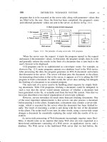
Creating Hatch Patterns
AutoCAD provides several predefined hatch patterns you can choose from, but you can also cre-
ate your own. This section demonstrates the basic elements of pattern definition.
Unlike linetypes, hatch patterns can’t be created while you’re in an AutoCAD file. The pat-
tern definitions are contained in an external file named acad.pat. You can open and edit this
file with a text editor that can handle ASCII files, such as Windows Notepad. Here is one hatch
pattern definition from that file:
*SQUARE,Small aligned squares
0, 0,0, 0,.125, .125, 125
90, 0,0, 0,.125, .125, 125
You can see some similarities between pattern descriptions and linetype descriptions. They both
start with a line of descriptive text and then give numeric values defining the pattern. However,
the numbers in pattern descriptions have a different meaning. This example shows two lines of
information. Each line represents a line in the pattern. The first line determines the horizontal line
component of the pattern, and the second line represents the vertical component (see the image to
the far right in Figure 28.30). A pattern is made up of line groups. A line group is like a linetype that
is arrayed a specified distance to fill the area to be hatched. A line group is defined by a line of code,
much as a linetype is defined. In the square pattern, for instance, two lines—one horizontal and
one vertical—are used. Each of these lines is duplicated in a fashion that makes the lines appear as
boxes when they’re combined. Figure 28.30 illustrates this point.
Look at the first line in the definition:
0, 0,0, 0,.125, .125, 125
This example shows a series of numbers separated by commas. It represents one line group.
It contains four sets of information, separated by blank spaces:
The first component is the
•u 0 at the beginning. This value indicates the angle of the line
group, as determined by the line’s orientation. In this case, it’s 0 for a horizontal line that
runs from left to right.
Figure 28.30
The individual
and combined
line groups
Groups merged
to form pattern
Vertical line group Horizontal line group
621974c28.indd 970 4/26/10 12:41:18 PM
Creating HatCH patterns
|
971
The next component is the origin of the line group, •u 0,0. This doesn’t mean the line begins
at the drawing origin (see Figure 28.31). It gives you a reference point to determine the loca-
tion of other line groups involved in generating the pattern.
The next component is
•u 0,.125. This determines the distance and direction for arraying the
line, as illustrated in Figure 28.32. This value is like a relative coordinate indicating X and Y
distances for a rectangular array. It isn’t based on the drawing coordinates, but on a coordinate
system relative to the orientation of the line. For a line oriented at a 0° angle, the code 0,.125
indicates a precisely vertical direction. For a line oriented at a 45° angle, the code 0,.125
represents a 135° direction. In this example, the duplication occurs 90° in relation to the line
group, because the X value is 0. Figure 28.33 illustrates this point.
The last component is the description of the line pattern. This value is equivalent to the
•u
value given when you create a linetype. Positive values are line segments, and negative
values are blank segments. This part of the line group definition works exactly as in the
linetype definitions you studied in the previous section.
This system of defining hatch patterns may seem somewhat limiting, but you can do a
lot with it. Autodesk managed to come up with 69 patterns—and that was only scratching
the surface.
Adding Thick Lines to Linetypes
If you want to include thick lines in your hatch patterns, you have to build up line widths with
multiple linetype definitions.
Figure 28.31
The origin of
the patterns
Light pattern shows
how the hatch relates
to the drawing origin.
Hatch pattern
Polyline defining hatch area
Origin of drawing (0,0)
621974c28.indd 971 4/26/10 12:41:19 PM
972
|
CHAPTER 28 Customizing toolbars, menus, linetypes, and HatCH patterns
The Bottom Line
Use workspaces. Often with AutoCAD, you find that you have different sets of panels or
toolbars open to perform specific tasks. You might have one set of Ribbon panels for editing
text and dimensions, whereas another set is more useful for design. Using workspaces is a
great way to organize your different editing modes.
Master It Where do you find the Customize option for workspaces?
Customize the user interface. In addition to using workspaces to organize tools and
Ribbon panels, you can customize the AutoCAD interface to make it fit the way you like
to work. You can add tools to Ribbon panels or even create your own tools for operations
you perform frequently.
Master It What does the Customizations In All Files group display?
Figure 28.32
The distance
and direction of
duplication
Result
Direction 0
Distance
0.125
0.125
Direction 90
0.125
Distance
Figure 28.33
How the direction
of the line group
copy is determined
The X and Y coordinate values given for the array distance are based on
the orientation of the line group.
621974c28.indd 972 4/26/10 12:41:20 PM
tHe bottom line
|
973
Create macros in tools and menus. A macro is a set of instructions that performs more com-
plex operations than single commands. Macros are often built on commands with additional
predefined responses to help speed data input.
Master It What does the ^C do in a macro?
Edit keyboard shortcuts. Keyboard shortcuts can help improve your speed when drawing
in AutoCAD. They can reduce several clicks of the mouse to a simple keystroke. AutoCAD
lets you create custom shortcuts for your favorite commands.
Master It What is the keyboard shortcut for Copy?
Save, load, and unload your customizations. To keep your customizations organized,
you can save new toolbars, menus, and Ribbons as files that you can load on demand.
When you save your custom elements as a file, you can move them to other computers.
Master It Name the tab that contains the group you use to save your custom elements.
Understand the Diesel macro language. If you’re adventurous, you may want to try your
hand at creating more-complex macros. The Diesel macro language is an easy introduction to
AutoCAD macro customization and is most useful in controlling the behavior in menu options.
Master It What does the expression $(getvar, blipmode) do?
Create custom linetypes. AutoCAD offers a number of noncontinuous linetypes, and
you may find them adequate for most of your work. But every now and then, you may
need a specific linetype that isn’t available. Creating custom linetypes is easy once you
understand the process.
Master It What is the purpose of a negative value in the linetype code?
Create hatch patterns. Like linetypes, the hatch patterns provided by AutoCAD will
probably fill most of your needs. But every now and then, you may need to produce a
specific pattern.
Master It How are a hatch pattern code and a linetype code similar?
621974c28.indd 973 4/26/10 12:41:20 PM
621974c28.indd 974 4/26/10 12:41:20 PM
Chapter 29
Managing and Sharing
Your Drawings
Whether you’re a one-person operation working out of your home or one of several hundred
AutoCAD users in a large company, file sharing and file maintenance can become the focus of
much of your time. In our interconnected world, the volume of messages and files crossing our
paths seems to be on the rise constantly. In addition, the Internet has enabled us to be more
mobile, adding yet more complexity to file-management tasks.
In this chapter, you’ll learn about some of the tools AutoCAD offers to help you manage
your files and the files you share with others. You’ll also examine some general issues that
arise while using AutoCAD in a workgroup environment. You may find help with problems
you’ve encountered when using AutoCAD in your particular work environment in the discus-
sion throughout the chapter.
In this chapter you’ll learn to do the following:
Share drawings over the Internet
•u
ePublish your drawings•u
Manage your drawings with DesignCenter and the tool palettes•u
Establish office standards•u
Convert multiple layer settings•u
Sharing Drawings over the Internet
The Internet has become a major part of our daily working lives. It provides AutoCAD users with
some real, practical benefits by giving them the ability to publish drawings and other documents
online. AutoCAD gives you tools that enable you to post drawings on the Internet that others can
view and download. In the architecture, engineering, and civil (AEC) industry in particular, this
can mean easier access to documents needed by contractors, engineers, cost estimators, and others
involved in the design, bidding, and construction of architectural projects. Suppliers of products
can post symbol libraries of their products or even 3D solid models.
In the following sections, you’ll learn about the tools AutoCAD provides for publishing and
accessing drawings over the Internet (and on any local or wide area network). You’ll start by
looking at one of the most common uses of the Internet: file transmission.
621974c29.indd 975 4/26/10 12:41:24 PM
976
|
CHAPTER 29 Managing and Sharing Your drawingS
Sharing Project Files with eTransmit
Perhaps the most common use of the Internet is sending and receiving files. Whether you’re
a 1-person office or a member of a 50-person firm, you’ll eventually have to share your work
with others outside your building. Before eTransmit existed as a feature in AutoCAD, you had
to examine what you were sending carefully to make sure you included all the ancillary files
needed to view or work on your drawings. Xref, font, and custom linetype files all had to be
included with the drawings that you sent to consultants or partners in a project, and often one
of these items was omitted from the transmission.
By using eTransmit, you can quickly collect all your project drawings into a single archive
file, or you can store the files in a separate folder for later processing. This collection of files is
included with a report file as a transmittal. Try the following to see how eTransmit works:
1. In AutoCAD, open a file you intend to send to someone and then choose Send eTransmit
from the Application menu to open the Create Transmittal dialog box (Figure 29.1). If you’ve
edited the file before choosing eTransmit, you will see a message telling you that you must
save the drawing before continuing.
2. In the dialog box, a tree structure lists the files that are included in the transmittal. If you
need to add more files to the transmittal than are shown in the list, you can click the Add
File button to open a file dialog box. To remove files, expand the listed item and remove
the checkmark that appears next to the file you want to exclude. You can also use the Files
Table tab to view the files as a simple list.
3. Click in the Enter Notes To Include With This Transmittal Package input box, and enter a
description or other note.
4. In the Select A Transmittal Setup group, click the Transmittal Setups button to open the
Transmittal Setups dialog box (Figure 29.2). From here, you can create a new transmittal
or rename or modify an existing one.
Figure 29.1
Creating a
transmittal
621974c29.indd 976 4/26/10 12:41:25 PM
Sharing drawingS over the internet
|
977
5. Click the Modify button to open the Modify Transmittal Setup dialog box (Figure 29.3).
6. In the Transmittal Package Type drop-down list, select the format for your collection of
files. You can create a Zip or self-extracting executable archive, or you can save the files
in a folder. If you choose the Zip or executable option, you can also add a password by
selecting the Prompt For Password check box in the Actions group of the dialog box. The
person receiving the transmittal file must then enter a password to extract the files. If
you choose the Folder option, you can tell AutoCAD where to place the files by using the
Browse button to the right of the Transmittal File Folder drop-down list. For this exercise,
choose the Folder option in the Transmittal Package Type list.
7. Click the Browse button to open the Specify Location Folder dialog box. This is a typical
AutoCAD file dialog box that you can use to select a location for your files. You can use
Figure 29.2
Choose whether to
create from scratch
or edit an existing
transmittal.
Figure 29.3
Set your transmit-
tal options.
621974c29.indd 977 4/26/10 12:41:25 PM
978
|
CHAPTER 29 Managing and Sharing Your drawingS
the Create New Folder tool to create a new folder for your files. You’ll want to keep your
transmittal files separate from other files. After you select a location, click Open to return
to the Modify Transmittal Setup dialog box.
8. After you’ve set up your transmittal, click OK. Then click Close in the Transmittal Setups
dialog box.
9. Preview the report file by clicking the View Report button in the Create Transmittal
dialog box. This report gives you a detailed description of the types of files included in
the transmittal. It also alerts you to files that AutoCAD was unable to find but that are
required for the drawing.
10. Close the report. After you’ve set up the eTransmit options, click OK in the Create
Transmittal dialog box.
11. If you selected the Zip option in step 6, you see the Specify Zip File dialog box. Enter a
name and a location for the file and AutoCAD collects the files into an archive folder or a
Zip file. You can then send the files over the Internet or put them on a removable disk for
manual transport. The EXE option works in a similar way.
You probably noticed that you can create additional transmittal setup options in the
Transmittal Setups dialog box. That way, you can have multiple transmittal options on hand
that you don’t have to set up each time a different situation arises. For example, you might have
the Standard setup configured to create a Zip file and another setup configured to copy the files
into a folder. A third setup might be created with a password.
Several options are available for configuring the transmittal setup. Table 29.1 gives a run-
down of those options.
Table 29.1: Modify Transmittal Setup dialog box options
Option Purpose
Transmittal Package Type Lets you select Folder, Zip, or Self-Extracting Executable.
File Format Lets you select 2010, 2007, 2004, or 2000 file formats in case your recipi-
ent requires an earlier version.
Maintain Visual Fidelity For
Annotative Objects
Maintains visual fidelity for annotative objects when drawings are
viewed in AutoCAD 2007 and earlier.
Transmittal File Folder Lets you determine the location for your transmittal package.
Transmittal File Name Not available if you select Folder as the transmittal package type. Options
are Prompt For A File Name, Overwrite If Necessary, and Increment File
Name If Necessary.
Use Organized Folder
Structure
Preserves the folder structure for the files in the transmittal. This
can be important when Xref and other files are located across several
folder locations.
Place All Files In One Folder Self-explanatory.
621974c29.indd 978 4/26/10 12:41:25 PM
Sharing drawingS over the internet
|
979
Option Purpose
Keep Files And Folders As Is Preserves the entire folder structure for the files in the transmittal.
Include Fonts Tells AutoCAD to include the font files in the transmittal.
Include Textures
From Materials
Lets you include bitmap files that are part of a file’s material settings.
Include Files From Data Links Lets you include external data-link files for tables.
Include Photometric Web Files Lets you include photometric web files for 3D lighting models.
Include Unloaded
File References
Include references for unloaded Xref files.
Send E-Mail With Transmittal Lets you send an e-mail with the files included as an attachment.
Set Default Plotter To ’None’ Removes any reference to printers or plotters that you’ve set up for the
drawing. (The type of printer you’ve set up for your files is stored with the
drawing file.)
Bind External References Lets you bind external references to the drawings that contain them if it
isn’t important for the recipient to maintain the external references as
separate drawings.
Prompt For Password Gives you the option to password-protect the transmittal file.
Purge Drawings Purge drawings of unused elements.
eTransmit gives you a quick way to package a set of files to be sent to others working on the
same project. But you may need to offer a wider distribution of your files. You might want to
let others view and plot your drawings from a website without exposing your drawing data-
base to anyone who might visit your site. If this sounds like something you’re interested in,
you’ll want to know about the AutoCAD DWF file format, which lets anyone view AutoCAD
files whether they own the program or not. You’ll learn more about the DWF file format in the
section “ePublishing Your Drawings” later in this chapter.
Protecting AutoCAD Drawing Files
Because AutoCAD drawings specify the methods and materials used to produce an object
or a building, they are frequently treated like legal documents. After an AutoCAD drawing
is issued, it’s often archived and guarded as a legal record of a design. For this reason, many
AutoCAD users are concerned about possible tampering with drawings that are sent to third
parties. Even minor, unauthorized changes to a drawing can have major repercussions to the
integrity of a design.
Table 29.1: Modify Transmittal Setup dialog box options (continued)
621974c29.indd 979 4/26/10 12:41:25 PM
980
|
CHAPTER 29 Managing and Sharing Your drawingS
AutoCAD 2011 offers tools that can help minimize file tampering. The eTransmit feature
offers a password-protection option to reduce the possibility of unauthorized tampering with
transmittal files. AutoCAD also offers password protection for individual files as well as a
digital-signature feature that helps protect both the author of a drawing and the recipient in
the event of file tampering.
Ad d i n g PA s s w o r d Pr o t e c t i o n t o Fi l e s
The basic type of file protection is password protection of individual files. AutoCAD offers
password protection through the Save Drawing As dialog box and the Options dialog box.
To add a password to a drawing when you save it, do the following:
1. Choose Save As from the Application menu to open the Save Drawing As dialog box.
2. Choose Tools Security Options from the menu in the upper-right corner of the dialog box.
3. In the Security Options dialog box, enter a password or phrase in the input box.
4. Click OK. You’re prompted to enter the password again.
5. Enter the password again, and click OK to return to the Save Drawing As dialog box.
6. Enter the name and location of your file, and then click Save.
In addition to the Save Drawing As dialog box, you can add password protection through the
Options dialog box:
1. Choose Options from the Application menu to open the Options dialog box, and then
click the Open And Save tab.
2. Click the Security Options button in the File Safety Precautions group to open the
Security Options dialog box.
3. Enter your password, select other options as necessary, and then click OK. You may have
to enter your password a second time to confirm.
As a third option, you can enter Securityoptions↵ at the Command prompt to go directly to
the Security Options dialog box.
After you’ve added a password, anyone attempting to open the file will be asked to provide
the password before the file can be opened. This includes any attempt to use the file as an Xref
or a file insertion.
AutoCAD Remembers That You’ve Opened a File
After you open a password-protected file and give the password, you can open and close the file
repeatedly during that AutoCAD session without having to reenter the password. If you close and
reopen AutoCAD, AutoCAD will prompt you for a password the next time you attempt to open the
password-protected file.
621974c29.indd 980 4/26/10 12:41:26 PM
Sharing drawingS over the internet
|
981
Us i n g A di g i t A l si g n A t U r e
In addition to password protection, you can use a digital signature to authenticate files. A digital
signature can’t prevent someone from tampering with a file, but it offers a way to validate whether
a file has been modified after it has been saved. This protects you in the event that your file is
unofficially altered. It also protects the recipient of your file by verifying the file’s authenticity and
by verifying that it was not altered from the time it left your computer.
The first time you attempt to use the digital signature feature, you see a message telling you
that you need a digital ID.
As the message explains, a digital ID is required to use the digital signature feature. AutoCAD
uses a digital ID issued by any certificate authority, such as, for example, VeriSign, a company that
specializes in Internet security. The VeriSign digital ID service is fee based, with prices ranging
from about $15 for a basic one-year enrollment to nearly $700 for a professional-level ID. A free
60-day trial is also offered. The following steps show how to acquire a digital ID:
1. Make sure you have a connection to the Internet.
2. From the Windows Taskbar, choose Start (All) Programs Autodesk AutoCAD 2011
Attach Digital Signatures. Or, from AutoCAD, enter Securityoptions↵ to open the Security
Options dialog box and then click the Digital Signature tab. The No Valid Digital ID Is
Available warning dialog box appears.
3. Click the Obtain ID button. Your web browser opens at the VeriSign page.
4. Select the security services you want, and follow the rest of the instructions.
After you’ve obtained a digital ID, the signature resides in the Registry on your computer.
You can then access the digital ID from AutoCAD by using the Digital Signature tab of the
Security Options dialog box. Here are the steps:
1. Open the drawing to which you want to attach the digital signature, and then open the
Security Options dialog box by entering Securityoptions↵ at the Command prompt.
2. Click the Digital Signature tab (Figure 29.4).
3. Select the Attach Digital Signature After Saving Drawing option. The Signature Information
options become available. You can add a date stamp and a brief description.
4. Click OK to exit the dialog box.
Figure 29.4
Attach a signature.
621974c29.indd 981 4/26/10 12:41:26 PM