Mastering AutoCAD 2008 and AutoCAD LT 2008 P2
Bạn đang xem bản rút gọn của tài liệu. Xem và tải ngay bản đầy đủ của tài liệu tại đây (780.13 KB, 10 trang )
6
CHAPTER 1
EXPLORING THE AUTOCAD AND AUTOCAD LT INTERFACE
The AutoCAD Window
The AutoCAD program window is divided into six parts:
◆
Menu bar
◆
Toolbars
◆
Drawing area
◆
Command window
◆
Status bar
◆
Dashboard
Figure 1.1, shown earlier in this chapter, shows a typical layout of the AutoCAD program win-
dow. Along the top is the
menu bar,
and just below that are the Workspaces and Standard Annotation
toolbars. At the bottom are the
Command window
and the
status bar.
To the right is the Dashboard. The
drawing area
occupies the rest of the screen. AutoCAD calls the window layout a
workspace
; you can
save and recall a workspace at any time using the Workspaces toolbar. The workspace in Figure 1.1
is called the 2D Drafting & Annotation workspace.
TIP
Your screen may show the drawing area in black. You can set the drawing area background
color by using the Options dialog box. Appendix A describes how to do this. The figures in this
book show the drawing area background in white for clarity.
Figure 1.2 shows AutoCAD’s 3D Modeling workspace, which has a different set of screen elements.
Figure 1.2 also shows a standard AutoCAD drawing file with a few setting changes to give it a 3D
appearance. Beneath these external changes, the underlying program is the same.
TIP
You’ll learn more about workspaces later in this chapter and in Chapter 26.
Figure 1.2
The 3D Modeling
workspace offers an
alternative arrange-
ment of the elements
in the AutoCAD
window.
3738x.book Page 6 Monday, June 25, 2007 11:37 PM
TAKING A GUIDED TOUR
7
The menu bar at the top of the drawing area (as shown in Figure 1.3) includes drop-down menus
from which you select commands in a typical Windows fashion. The toolbars and Dashboard pro-
vide a variety of commands through tool buttons and drop-down lists.
Figure 1.3
The menu bar, the
Workspaces toolbar,
and the Standard
Annotation toolbar.
LT users may see a
floating Workspaces
toolbar instead of the
docked version shown
at far right.
The drawing area occupies most of the screen. Everything you draw appears in this area. As you
move your mouse around, crosshairs appear to move within the drawing area. This is the drawing
cursor that lets you point to locations in the drawing area.
At the bottom of the drawing area is a set of tabs. These tabs give you access to the Layout views
of your drawing. These views let you lay out your drawing as in a desktop publishing program.
You’ll learn about the Layout tabs in Chapter 8. The arrows to the left of the tabs let you navigate
the tabs when there are more tabs than can fit in the AutoCAD window.
The Command window, located just below the Layout tabs, gives you feedback about AutoCAD’s
commands as you use them. You can move and resize this window just as you move and resize tool-
bars. By default, the Command window is in its docked position, as shown in Figure 1.4.
Figure 1.4
The Command win-
dow and the status bar
Workspaces toolbar Standard Annotation toolbar Communication Center
Menu
bar
Dashboard
(not shown)
Turning on the Tabs
If you don’t see the tabs, don’t worry. AutoCAD can be set up to hide the tabs, but you can easily restore them
to view. To turn them on, locate the Model tool in the status bar at the bottom of the AutoCAD window.
Right-click the Model tool, and then select Display Layout and Model Tabs. The tabs will appear just
below the drawing area. To hide the tabs, right-click any tab, and select Hide Layout and Model Tabs.
USC icon
Command prompt Command window
Coordinate readout Status bar
3738x.book Page 7 Monday, June 25, 2007 11:37 PM
8
CHAPTER 1
EXPLORING THE AUTOCAD AND AUTOCAD LT INTERFACE
Below the Command window is the status bar (see Figure 1.4). The status bar gives you infor-
mation at a glance about the state of the drawing. For example, the coordinate readout toward the
far left of the status bar tells you the location of your cursor.
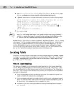
Picking Points in the Drawing Area
Now that you’ve seen the general layout of AutoCAD, try using the coordinate readout and the
drawing cursor to get a sense of how the parts of the AutoCAD screen work together:
1.
Move the cursor around in the drawing area. As you move it, notice how the coordinate read-
out changes to tell you the cursor’s location. It shows the coordinates in an X, Y, Z format.
2.
Place the cursor in the middle of the drawing area, and click the left mouse button. Move the
cursor, and a rectangle follows. This is a
window selection;
you’ll learn more about this win-
dow in Chapter 2. You also see a coordinate readout following the cursor and a message ask-
ing you to S
pecify opposite corner:
. This display at the cursor is called the
dynamic input
.
You’ll learn more about it a little later in this chapter.
TIP
If you don’t see the dynamic input display, click the button labeled DYN in the status bar to
turn it on.
3.
Move the cursor a bit in any direction; then, click the left mouse button again. Notice that the
window selection disappears, as does the dynamic input display.
4.
Try picking several more points in the drawing area. Notice that as you click the mouse, you
alternately start and end a window selection.
If you happen to click the right mouse button, a shortcut menu appears. A right-click frequently
opens a menu containing options that are
context sensitive.
This means the contents of the shortcut
menu depend on the location where you right-click as well as the command that is active at the time
of your right-click. If there are no appropriate options at the time of the right-click, AutoCAD treats
the right-click as an
↵
. You’ll learn more about these options as you progress through the book. For
now, if you happen to open this menu by accident, press the Esc key to close it.
The UCS Icon
In the lower-left corner of the drawing area, you see an L-shaped arrow. This is the
User Coordinate
System (UCS)
icon, which tells you your orientation in the drawing. This icon becomes helpful as
you start to work with complex 2D drawings and 3D models. The X and Y arrows indicate the X and
Y axes of your drawing. The little square at the base of the arrows tells you that you’re in what is
called the
World Coordinate System.
Chapter 21 discusses this icon in detail. For now, you can use it
as a reference to tell you the direction of the axes.
3738x.book Page 8 Monday, June 25, 2007 11:37 PM
TAKING A GUIDED TOUR
9
The Command Window
At the bottom of the screen, just above the status bar, is a small horizontal window called the
Com-
mand window.
Here, AutoCAD displays responses to your input. By default, it shows two lines of text.
The bottom line shows the current messages, and the top line shows messages that have scrolled by
or, in some cases, components of the current message that don’t fit in a single line. Right now, the bot-
tom line displays the message
Command
(see Figure 1.4, earlier in this chapter). This
prompt
tells you
that AutoCAD is waiting for your instructions. When you click a point in the drawing area, you see
the message
Specify opposite corner:
. At the same time, the cursor starts to draw a window selec-
tion that disappears when you click another point. The same message appears in the dynamic input
display at the cursor.
As a new user, pay special attention to messages displayed in the Command window and the
dynamic input display because this is how AutoCAD communicates with you. Besides giving you
messages, the Command window records your activity in AutoCAD. You can use the scroll bar to
the right of the Command window to review previous messages. You can also enlarge the window
for a better view. (Chapter 2 discusses these components in more detail.)
Now, let’s look at AutoCAD’s window components in detail.
TIP
The Command window and the dynamic input display allow AutoCAD to provide text feed-
back to your actions. You can think of these features as a chat window to AutoCAD—as you enter
commands, AutoCAD responds with messages. As you become more familiar with AutoCAD, you
may find you don’t need to rely on the Command window and dynamic input display as much.
For new and casual users, however, the Command window and dynamic input display can be
helpful in understanding what steps to take as you work.
The Drop-Down Menus
As in most Windows programs, the drop-down menus on the menu bar provide an easy-to-understand
way to access AutoCAD’s general controls and settings. In these menus, you’ll find the commands and
functions that are the heart of AutoCAD. By clicking menu items, you can cut and paste items to and
from AutoCAD, change the settings that make AutoCAD work the way you want it to, set up the mea-
surement system you want to use, access the help system, and much more.
The drop-down menu options perform three basic functions:
◆
Display a dialog box that contains settings you can change.
◆
Issue a command to create or modify your drawing.
◆
Offer an expanded set of the same tools found in the Draw and Modify toolbars.
As you point to commands and options in the menus, AutoCAD provides additional help for
you in the form of brief descriptions of each menu option, which appear in the status bar.
If You Can’t Find the UCS Icon
The UCS icon can be turned on and off, so if you’re on someone else’s system and you don’t see the
icon, don’t panic. If you don’t see the icon or it doesn’t look as it does in this chapter, see Chapter 21
for more information.
3738x.book Page 9 Monday, June 25, 2007 11:37 PM
10
CHAPTER 1
EXPLORING THE AUTOCAD AND AUTOCAD LT INTERFACE
Here’s an exercise to let you practice with the drop-down menus and get acquainted with the
way you issue AutoCAD commands:
1.
Click View in the menu bar. The list of items that appears includes the commands and set-
tings that let you control the way AutoCAD displays your drawings. Don’t worry if you
don’t understand them yet; you’ll get to know them in later chapters.
WARNING
LT users won’t see the Render option in the View menu.
2.
Move the highlight cursor slowly down the list of menu items. As you highlight each item,
notice that a description of it appears in the status bar at the bottom of the AutoCAD win-
dow. These descriptions help you choose the menu option you need.
TIP
If you look carefully at the command descriptions in the status bar, you’ll see an odd word at the
end. This is the keyboard command equivalent to the highlighted option in the menu or toolbar.
You can type these keyboard commands to start the tool or menu item that you’re pointing to. You
don’t have to memorize these command names, but knowing them will be helpful to you later if
you want to customize AutoCAD.
3.
Some of the menu items have triangular pointers to their right. This means the command has
additional choices. For instance, highlight the Zoom item, and another set of options appears
to the right. This second set of options is called a
cascading menu.
Whenever you see a drop-
down menu item with the triangular pointer, you know that this item opens a cascading
menu offering a more detailed set of options.
4.
Other drop-down menu options are followed by an ellipsis (…). This indicates that the
option displays a dialog box. For instance, move the highlight cursor to the Tools option in
the menu bar.
TIP
If you prefer, you can click and drag the highlight cursor over the drop-down menu to select
an option.
3738x.book Page 10 Monday, June 25, 2007 11:37 PM